EP0895572B1 - Obus de petit calibre - Google Patents
Obus de petit calibre Download PDFInfo
- Publication number
- EP0895572B1 EP0895572B1 EP97921018A EP97921018A EP0895572B1 EP 0895572 B1 EP0895572 B1 EP 0895572B1 EP 97921018 A EP97921018 A EP 97921018A EP 97921018 A EP97921018 A EP 97921018A EP 0895572 B1 EP0895572 B1 EP 0895572B1
- Authority
- EP
- European Patent Office
- Prior art keywords
- shell
- casing
- core
- calibre
- penetrator
- Prior art date
- Legal status (The legal status is an assumption and is not a legal conclusion. Google has not performed a legal analysis and makes no representation as to the accuracy of the status listed.)
- Expired - Lifetime
Links
Images

Classifications
-
- F—MECHANICAL ENGINEERING; LIGHTING; HEATING; WEAPONS; BLASTING
- F42—AMMUNITION; BLASTING
- F42B—EXPLOSIVE CHARGES, e.g. FOR BLASTING, FIREWORKS, AMMUNITION
- F42B12/00—Projectiles, missiles or mines characterised by the warhead, the intended effect, or the material
- F42B12/02—Projectiles, missiles or mines characterised by the warhead, the intended effect, or the material characterised by the warhead or the intended effect
- F42B12/04—Projectiles, missiles or mines characterised by the warhead, the intended effect, or the material characterised by the warhead or the intended effect of armour-piercing type
- F42B12/06—Projectiles, missiles or mines characterised by the warhead, the intended effect, or the material characterised by the warhead or the intended effect of armour-piercing type with hard or heavy core; Kinetic energy penetrators
Definitions
- the present invention relates to a new improved small-calibre shell with a certain armour-piercing capacity.
- the shell according to the invention is of the basic type which includes an outer casing made of a thinner metal material such as tombac, tombac-plated sheet steel or the like, which defines the outer shape of the shell, and a shell core enclosed therein made of extremely hard armour-piercing material such as hard metal, heavy metal or equivalent.
- a relevant example of such a prior art armour-piercing shell is described in DE-C-327539.
- Said shell is comprising an outer casing, a central core of an armour piercing material and a heavy metal filling, which is surrounding the core and entirely filling up the casing.
- a hard metal plate is arranged in contact with the rear end of the core with the intention to increase the amount of energy delivered to the core.
- Previously known so-called armour-piercing small-calibre shells have very generally consisted of an outer casing made of a relatively thin sheet material which in most cases consisted of tombac, tombac-plated sheet steel or equivalent and a core enclosed therein made of an extremely hard material which often consisted of hard metal which is actually not a metal or metal alloy of course but rather various types of metal carbides and then chiefly tungsten carbides, or heavy metal which in most cases is tungsten alloys.
- the armour-piercing core in previous types of armour-piercing small-calibre shells was shorter than and sometimes also of smaller calibre than the inside of the casing.
- the shells therefore as a rule also contained various types of filling material in order to fill out the interior of the casing and hold the armour-piercing core in place until the shell reached its target.
- the armour-piercing capacity of the armour-piercing small-calibre shells is of course clearly limited but, as the use of anti-splinter armours has increased to a very great extent in recent years and as the armour-piercing small-calibre ammunition can under favourable circumstances deal with targets of this type, the need for this type of ammunition can be expected to continue to increase.
- the greatest problem with the current generation of armour-piercing small-calbire ammunition is that, quite generally, it has such great differences as far as the ballistic characteristics of the shells it includes, compared with corresponding standard ammunition of the same calibre, that precision shooting with mixed ammunition or rapid changing between different ammunition types is made considerably more difficult.
- the aim of the present invention is to offer a new type of small-calibre shell with a certain very good - with regard to its own calibre - armour-piercing effect and, probably its greatest advantage, with such an inner construction that its ballistic data can easily be adapted so as to be very close to or even be made completely identical with the majority of standard ammunition types with the calibre range concerned.
- Shells designed in accordance with the invention moreover have such good and uniform precision that they fall into the same class as the so-called sniper or special ammunition for marksmen.
- the present invention thus relates to a small-calibre shell with a certain armour-piercing capacity of the type which comprises an elongate, preferably solid shell core or penetrator which is axially centred inside a hollow shell casing and which has a cylindrical main part and a tip which tapers conically forwards in the intended flight direction of the shell in one or more stages.
- the tip of the shell core itself can thus have the shape of one or more successive frustoconical parts of ever greater apex angles and a concluding conical part, or alternatively a single conical tip.
- the outer shape of the shell on the other hand is defined entirely by the shell casing and this is therefore designed from the outset with the conical tip which is appropriate for each specific shell type.
- the invention is characterized in the first place in that the shell cores or penetrators are centred around the longitudinal axis of the shell casing, that is to say of the future finished shell, between a first accurate bearing or support against the inside of the shell casing in the front conically pointed part of the shell and a second bearing in the rear part of the shell by means of a support part or insert which is arranged inside the casing and contains at least the very rearmost part of the shell core and which in turn is held in place in the casing by a ballast material which completely fills the rearmost part of the casing.
- the bearing between the inside of the shell core and the front part of the penetrator takes place either along one of the frustoconical parts of the shell core tip or along the transition or interruption edge between two parts which may be constituted by the cylindrical part of the shell core and its single-coned tip or alternatively by different parts of the coned tip.
- edge(s) which in this connection form(s) the transition between the tip and the cylindrical part or alternatively between different parts of the tip coned in a number of stages is then a natural circumferential bearing line for centring the front part of the penetrator against the inside of the casing well into the part of the same which forms the tip of the shell, providing of course that the penetrator has a smaller diameter than the inside of the shell casing and also a more obtuse apex angle on its own tip than the inner apex angle of the casing.
- the possibility of locating the bearing of the shell core against the inside of the casing along an entire frustoconical surface is selected in particular when there is a need for the greater friction contact surface, which is then obtained, in order to ensure that the shell core does not have a tendency to remain still inside the rotationally stabilized casing, that is to say in ammunition types with extremely high speed of rotation.
- the armour-piercing shell core is very well supported and centred in the shell casing right up to the moment that the shell reaches the target.
- the ballistic data of the shell can easily be modified by adjusting the ratio between the weight of the ballast material and of the support part respectively, which can be done both by varying the material selected in the different parts and by varying their mutual volume ratios.
- the same armour-piercing shell core can be used in a number of different adjacent calibres, of which there are of course a large number intended mainly for lighter handheld firearms and this will of course mean considerable cost savings.
- the support part or insert As far as the support part or insert is concerned, this can be made of any material with sufficiently good strength and mouldability. Steel or aluminium, for example, is a good material but the possibility of using certain plastics for this purpose is not inconceivable.
- the ballast material filling the rearmost part of the casing As far as the ballast material filling the rearmost part of the casing is concerned, this is required to be plastically deformable so that it can be given the desired final shape at the same time as allowing the rearmost part of the shell to be finally shaped in a manner known per se including folding-in at the rear of the rear outer edge of the casing at the same time as possibly equipping with a so-called boat tail end by upsetting.
- the armour-piercing core or penetrator can advantageously be given the shape of an elongate cylinder which also has, in addition to the tip which tapers conically in one or more stages, a frustoconical rear end.
- This frustoconical end provides an excellent support for the part of the penetrator which the support part or insert overlaps, that is to say the part of the penetrator which is inserted into the insert.
- the contact line between the penetrator and the inside of the casing is to lie in the part of the casing which forms the tip of the finished shell and the penetrator must therefore have a diameter which is at least slightly smaller than the maximum internal dimension of the casing, there will be in many shell calibres an accessible space between the inside of the shell casing and the penetrator which allows the support part or insert to continue at least some way along the cylindrical part of the penetrator.
- the shell casing as a rule has a softer shape than the shell core, a thin tubular first empty space is formed immediately in front of the support part and a second empty space is formed at the very front inside the shell tip.
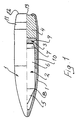
- the two figures show shells with slightly different outer shape but the major difference resides in the fact that the shell cores included in the respective shells are of different types.
- the shell according to Fig. 1 has a shell core with a single-coned tip while the shell according to Fig. 2 has a tip coned in a number of stages.
- the shell shown in Fig. 1 consists of an outer shell casing 1 made of, for example, tombac or tombac-plated sheet steel, and the inner shell core or penetrator 2 which is made of hard metal, heavy metal or another equivalent material. Also included is a support part or insert 3 which can, for example, be made of aluminium, steel or another suitable material. Finally, the ballast material, designated 4, is included, which fills the rearmost part of the shell casing and in the example shown consists of a lead alloy containing 1-10% antimony.
- the shell casing 1 which defines the outer shape of the shell while the shell core or penetrator 2 has a considerably simpler shape with a single conical tip 5, an elongate cylindrical main part 6 and a short frustoconical rear part 7.
- the peripheral edge line 8 which forms the transition between the conical tip 5 of the penetrator and its cylindrical part 6 also forms, as can be seen from the figure, the bearing edge against the front pointed inside of the casing which gives the penetrator its front support.
- the support part or insert 3 is mainly that part of the same, with reference number 9, overlapping the frustoconical rear part 7 of the penetrator, which is responsible for the rear support of the penetrator 2, even though the support part 3, as can be seen from the figure, extends with its neck part 10 forward along the cylindrical part 6 of the penetrator, which is allowed by the clearance between the latter and the inside of the casing 1.
- the rear part of the shell casing is upset in to form a so-called boat tail 11 and at the same time as this, which is carried out as a final operation, the rear edge 12 of the casing has also been upset in towards the rear plane 13 of the shell.
- the shell is otherwise manufactured in such a manner that the shell casing 1 in its front pointed part is preformed to on the whole final dimensions while its rear part is only preformed and subsequently the finished penetrator 2 and the support part 3 are guided into place followed by the only preformed ballast part 4, whereupon the middle and rear parts of the shell are given their final shape and dimensions.
- the shell shown in Fig. 2 is produced in a manner corresponding to that in Fig. 1 and in principle from the same materials.
- the casing 14 has a somewhat different shape but above all the shell core 15 is made with a double-coned tip, the first part of which consists of a frustoconical part 16 with a given first apex angle ⁇ and the second part 17 of which consists of a completely conical part with a substantially greater apex angle ⁇ .
- the shell tip thus has a double-interrupted side edge line.
- Other tip constructions which include a number of frustoconical parts following one another with successively greater apex angles, also fall within the same basic construction of course.
- the support part 18 which has the same basic construction as the support part 3 in Fig. 1. Also included is a ballast part 19 consisting of lead alloyed with antimony. The end of the shell has been formed with a pronounced boat tail 20 in the same manner as the corresponding detail in Figure 1.
- the contact between the front part of the shell core 15 and the inside of the shell casing 14 is transferred completely to the frustoconical part 16 of the former.
- the shell according to the invention therefore comprises the six different components, the shell casing, the shell core, the support part, the ballast material and also the first and second empty spaces, the differing size, shape and axial displacement of which can be varied in order to impart the desired ballistic data to the finished shell.
- the selection of material in the different parts, with the exception, of course, of the empty spaces, can also be varied within the limits applying for the function of the various parts.
Landscapes
- Engineering & Computer Science (AREA)
- Chemical & Material Sciences (AREA)
- Combustion & Propulsion (AREA)
- General Engineering & Computer Science (AREA)
- Road Signs Or Road Markings (AREA)
- Aiming, Guidance, Guns With A Light Source, Armor, Camouflage, And Targets (AREA)
- Table Devices Or Equipment (AREA)
- Containers Having Bodies Formed In One Piece (AREA)
- Forging (AREA)
- Earth Drilling (AREA)
- Toys (AREA)
Claims (8)
- Obus de petit calibre ayant un certain pouvoir perforant et une précision extrêmement élevée, du type général, qui comprend un noyau ou pénétrateur (2) d'obus allongé, de préférence solide, fabriqué à partir de métal dur fritté, de métal lourd ou d'un autre matériau extrêmement dur et lourd qui est centré de manière axiale à l'intérieur d'une gaine métallique creuse (1) définissant la forme extérieure de l'obus avec son extrémité avant conique et son extrémité arrière, caractérisé en ce que le noyau ou le pénétrateur de l'obus (2) est centré autour de l'axe longitudinal du futur obus fini entre un premier coussinet ou support précis (8) contre l'intérieur de la gaine de l'obus (1) dans la partie avant pointue de manière continuellement conique de l'obus et un second coussinet dans la partie arrière de l'obus au moyen d'une partie formant support ou intercalaire (3) qui est agencée à l'intérieur de la gaine de l'obus (1) et contient au moins la partie la plus en arrière (7) du noyau de l'obus, et qui est à son tour maintenue en place à l'intérieur de la gaine de l'obus (1) par du matériau de ballast (4) qui remplit complètement la partie la plus en arrière de ce dernier.
- Obus de petit calibre selon la revendication 1, caractérisé en ce que le noyau ou pénétrateur (2) de l'obus se présente sous la forme d'une barre cylindrique (6) avec une extrémité avant conique (5), le coussinet avant du noyau de l'obus (2) contre l'intérieur de la gaine de l'obus se trouvant le long de la transition de bord (8) entre la forme cylindrique (6) et l'extrémité conique (5).
- Obus de petit calibre selon la revendication 1, caractérisé en ce que le noyau ou pénétrateur de l'obus (15) se présente, dans sa partie principale, sous la forme d'une barre cylindrique, munie d'une extrémité qui s'amincit vers l'avant dans au moins deux phases dans la direction envisagée pour le vol de l'obus, chaque phase ayant une forme tronconique, à l'exception de la dernière phase qui a une forme complètement conique, et les différentes phases ayant des angles du sommet (α, σ) qui augmentent dans la direction de vol.
- Obus de petit calibre selon la revendication 1, 2 ou 3, caractérisé en ce que l'extrémité du pénétrateur (2) se présente sous la forme d'un cône tronqué (7) et la partie formant support ou intercalaire (3) chevauche au moins cette partie d'extrémité conique (7).
- Obus de petit calibre selon l'une quelconque des revendications 1 à 4, caractérisé en ce que le noyau ou pénétrateur de l'obus (2) a un calibre plus petit que le diamètre interne le plus grand de la gaine de l'obus (1) et en ce que la partie formant support ou insert (3) contenant la partie le plus en arrière (7) du noyau de l'obus (2), aussi loin qu'elle s'étend, remplit complètement l'espace entre la partie arrière du noyau de l'obus et l'intérieur de la gaine de l'obus.
- Obus de petit calibre selon l'une quelconque des revendications 1 à 5, caractérisé en ce que la partie de la partie formant support ou intercalaire (3), qui contient ou chevauche le noyau ou le pénétrateur de l'obus (2), s'étend aussi loin vers l'avant le long de ce dernier (2) que la forme de l'obus et l'épaisseur réelle du matériau s'y trouvant de la partie formant support ou intercalaire (3) le permettent, tandis qu'un espace vide est formé devant celle-ci et vers l'avant en direction dudit premier coussinet (8, 16).
- Obus de petit calibre selon l'une quelconque des revendications 1 à 6, caractérisé en ce que le matériau de ballast (4) remplissant complètement la partie la plus en arrière (7) de la gaine de l'obus (1) peut être déformé de manière plastique de telle sorte qu'un ajustement correct ainsi qu'une étanchéité au gaz contre l'intérieur de l'extrémité de la gaine puissent être obtenus lorsque cette dernière est finalement formée de manière connue, afin de former, par exemple, ce que l'on appelle l'arrière du missile (11).
- Obus de petit calibre selon l'une quelconque des revendications 1 à 7, caractérisé en ce que le matériau de ballast (4) se compose de plomb ou d'un alliage de plomb.
Applications Claiming Priority (3)
| Application Number | Priority Date | Filing Date | Title |
|---|---|---|---|
| SE9601590A SE508476C2 (sv) | 1996-04-26 | 1996-04-26 | Finkaliberprojektil |
| SE9601590 | 1996-04-26 | ||
| PCT/SE1997/000608 WO1997041404A1 (fr) | 1996-04-26 | 1997-04-11 | Obus de petit calibre |
Publications (2)
| Publication Number | Publication Date |
|---|---|
| EP0895572A1 EP0895572A1 (fr) | 1999-02-10 |
| EP0895572B1 true EP0895572B1 (fr) | 2002-07-03 |
Family
ID=20402350
Family Applications (1)
| Application Number | Title | Priority Date | Filing Date |
|---|---|---|---|
| EP97921018A Expired - Lifetime EP0895572B1 (fr) | 1996-04-26 | 1997-04-11 | Obus de petit calibre |
Country Status (6)
| Country | Link |
|---|---|
| US (1) | US6286433B1 (fr) |
| EP (1) | EP0895572B1 (fr) |
| AT (1) | ATE220198T1 (fr) |
| DE (1) | DE69713760T2 (fr) |
| SE (1) | SE508476C2 (fr) |
| WO (1) | WO1997041404A1 (fr) |
Cited By (1)
| Publication number | Priority date | Publication date | Assignee | Title |
|---|---|---|---|---|
| EP4283244B1 (fr) * | 2022-05-25 | 2024-11-13 | Metallwerk Elisenhütte GmbH | Projectile pour cartouche d'arme à feu portative à noyau dur et son procédé de fabrication |
Families Citing this family (27)
| Publication number | Priority date | Publication date | Assignee | Title |
|---|---|---|---|---|
| RU2169898C2 (ru) * | 1999-08-19 | 2001-06-27 | Волохов Валерий Анатольевич | Бронебойная пуля |
| RU2183007C1 (ru) * | 2000-10-17 | 2002-05-27 | Центральный научно-исследовательский институт точного машиностроения | Пуля |
| RU2170407C1 (ru) * | 2000-12-20 | 2001-07-10 | ОАО "Тульский патронный завод" | Патрон для личного огнестрельного оружия и бронебойная пуля для него |
| FR2821151B1 (fr) | 2001-02-16 | 2004-05-28 | Manurhin Defense | Projectile perforant pour une munition de petit ou de moyen calibre et procede de montage d'un tel projectile perforant |
| RU2206052C2 (ru) * | 2001-06-18 | 2003-06-10 | Открытое акционерное общество "Барнаульский станкостроительный завод" | Патрон стрелкового оружия |
| RU2195626C1 (ru) * | 2001-10-12 | 2002-12-27 | Федеральное государственное унитарное предприятие "Центральный научно-исследовательский институт точного машиностроения" | Пуля |
| US6973879B1 (en) | 2002-03-16 | 2005-12-13 | Mcelroy Hugh Anthony | Monolithic high incapacitation small arms projectile |
| RU2247308C1 (ru) * | 2004-02-02 | 2005-02-27 | Закрытое Акционерное Общество "Дальневосточная Технология" (Зао "Дв-Технология") | Сердечник пули |
| RU2284451C2 (ru) * | 2004-05-05 | 2006-09-27 | Государственное Унитарное Предприятие "Конструкторское Бюро Приборостроения" (Гуп "Кбп") | Пуля бронебойного патрона |
| US7520224B2 (en) * | 2006-04-06 | 2009-04-21 | John D. Taylor | Advanced armor-piercing projectile construction and method |
| RU2327947C2 (ru) * | 2006-07-06 | 2008-06-27 | Иркутское высшее военное авиационное инженерное училище (военный институт) | Бронебойно-зажигательная пуля с полимерной оболочкой |
| DE202013101559U1 (de) | 2013-04-12 | 2013-06-05 | Tribo Hartstoff Gmbh | Projektilkern für ein Mantelgeschoss |
| MX2018004741A (es) * | 2015-10-18 | 2018-08-01 | Reilly William | Proyectil de submasa para arma de fuego de carga automatica y metodos. |
| US10436557B2 (en) * | 2016-04-18 | 2019-10-08 | Ammo Technologies, Inc. | Armor-piercing projectile |
| US11293730B1 (en) * | 2016-06-14 | 2022-04-05 | Douglas Burke | Bullet projectile with enhanced mechanical shock wave delivery for warfare |
| US20180038673A1 (en) * | 2016-08-05 | 2018-02-08 | Jason Fridlund | Ammunition projectile having improved aerodynamic profile and method for manufacturing same |
| DK3507565T3 (da) | 2016-09-02 | 2022-12-19 | Saltech Ag | Projektil med penetrator |
| US20190017791A1 (en) * | 2017-03-07 | 2019-01-17 | U.S. Army Research Laboratory Attn: Rdrl-Loc-I | Reduced Jacketed Bullet Bore Resistance |
| DE102017112889A1 (de) | 2017-06-12 | 2018-12-13 | Rheinmetall Waffe Munition Gmbh | Kleinkalibergschoss sowie Kleinkalibermunition mit einem derartigen Kleinkalibergeschoss |
| US11841214B2 (en) * | 2017-06-23 | 2023-12-12 | Douglas Burke | Bullet projectile with internal hammer and post for enhanced mechanical shock wave delivery for demolition |
| CN114623732B (zh) * | 2022-03-25 | 2023-09-08 | 中国工程物理研究院总体工程研究所 | 一种适用于厚壁弹药冲击引爆的复合毁伤元结构 |
| US20240102779A1 (en) * | 2022-09-26 | 2024-03-28 | Sig Sauer, Inc. | Multi-piece projectile |
| DE102023105717A1 (de) | 2023-03-08 | 2024-09-12 | Swissp Defence Ag | Mantelgeschoss |
| DE102023105714A1 (de) | 2023-03-08 | 2024-09-12 | Swissp Defence Ag | Mantelgeschoss |
| DE102023105716A1 (de) | 2023-03-08 | 2024-09-12 | Swissp Defence Ag | Mantelgeschoss |
| DE102023105715A1 (de) | 2023-03-08 | 2024-09-12 | Swissp Defence Ag | Mantelgeschoss |
| US12253340B1 (en) * | 2023-09-01 | 2025-03-18 | True Velocity IP Holdings, Inc. | Thermal tipped penetrator bullet |
Family Cites Families (9)
| Publication number | Priority date | Publication date | Assignee | Title |
|---|---|---|---|---|
| DE327539C (de) | 1913-11-16 | 1920-10-12 | Maximilian Rudolf Heide | Mantelgeschoss |
| DE308457C (de) * | 1918-04-25 | 1920-01-08 | Becker Ludwig | Brandgeschoss mit stahlkern |
| FR826922A (fr) | 1936-12-31 | 1938-04-13 | Perfectionnements aux projectiles perforants | |
| GB601686A (en) * | 1942-02-27 | 1948-05-11 | Lumalampan Ab | Improvements in and relating to projectiles |
| NL175341C (nl) * | 1970-10-28 | 1984-10-16 | Eurometaal Nv | Werkwijze voor het samenstellen van een uit een vuurwapen te verschieten kogel met een kern van hard materiaal, alsmede kogel vervaardigd onder toepassing van die werkwijze. |
| DE3209594A1 (de) | 1982-03-17 | 1983-09-29 | L'Etat Français représenté par le Délégué Général pour l'Armement, 75997 Paris | Panzerbrechendes wuchtgeschoss insbesondere zum bekaempfen von mehrplattenzielen |
| US4625650A (en) * | 1984-10-29 | 1986-12-02 | Olin Corporation | Multiple effect ammunition |
| CA1333543C (fr) * | 1987-10-05 | 1994-12-20 | Jean-Pierre Denis | Projectile destine a etre tire par une arme a feu |
| US5020439A (en) * | 1989-05-05 | 1991-06-04 | Olin Corporation | Projectile having improved baseplug |
-
1996
- 1996-04-26 SE SE9601590A patent/SE508476C2/sv not_active IP Right Cessation
-
1997
- 1997-04-11 US US09/171,099 patent/US6286433B1/en not_active Expired - Lifetime
- 1997-04-11 DE DE69713760T patent/DE69713760T2/de not_active Expired - Lifetime
- 1997-04-11 WO PCT/SE1997/000608 patent/WO1997041404A1/fr not_active Ceased
- 1997-04-11 EP EP97921018A patent/EP0895572B1/fr not_active Expired - Lifetime
- 1997-04-11 AT AT97921018T patent/ATE220198T1/de active
Cited By (1)
| Publication number | Priority date | Publication date | Assignee | Title |
|---|---|---|---|---|
| EP4283244B1 (fr) * | 2022-05-25 | 2024-11-13 | Metallwerk Elisenhütte GmbH | Projectile pour cartouche d'arme à feu portative à noyau dur et son procédé de fabrication |
Also Published As
| Publication number | Publication date |
|---|---|
| US6286433B1 (en) | 2001-09-11 |
| SE9601590L (sv) | 1997-10-27 |
| DE69713760T2 (de) | 2002-12-05 |
| EP0895572A1 (fr) | 1999-02-10 |
| SE508476C2 (sv) | 1998-10-12 |
| ATE220198T1 (de) | 2002-07-15 |
| WO1997041404A1 (fr) | 1997-11-06 |
| DE69713760D1 (de) | 2002-08-08 |
Similar Documents
| Publication | Publication Date | Title |
|---|---|---|
| EP0895572B1 (fr) | Obus de petit calibre | |
| US6374743B1 (en) | Jacketed projectile with a hard core | |
| US6845717B1 (en) | Bullet with an internally carried sub-projectile | |
| JP4249220B2 (ja) | 4.6mm小火器用弾薬 | |
| US6105506A (en) | Sabot slug for shotgun | |
| US20140326157A1 (en) | Jacketed bullet | |
| US5794320A (en) | Core bullet manufacturing method | |
| US4662280A (en) | Explosive and incendiary projectile | |
| CA2554491A1 (fr) | Balle enrobee a noyau monobloc | |
| AU717451B2 (en) | Expansion projectile | |
| JP4249219B2 (ja) | 5.56mm小火器用弾薬 | |
| US5148750A (en) | Unitary projectile | |
| IL291454B2 (en) | Penetrator, use of a penetrator, and projectile | |
| US3862600A (en) | Multi-projectile assembly | |
| US20240102779A1 (en) | Multi-piece projectile | |
| US5009167A (en) | High-explosive projectile | |
| US3977324A (en) | Sabotless micro projectile | |
| NO334506B1 (no) | Blyfritt prosjektil. | |
| US7311046B2 (en) | Bullet for infantry ammunition | |
| AU2023331903A1 (en) | Projectile with reduced running load | |
| EP0129608B1 (fr) | Projectile pour arme à feu | |
| GB2071824A (en) | Projectile more especially an armourpiercing projectile | |
| NO312608B1 (no) | Prosjektil som inneholder en tung kjerne som er omgitt av en mantel | |
| US12123688B2 (en) | Penetrator, use of a penetrator, and projectile | |
| RU2717325C1 (ru) | Двуоболочечная бронебойная пуля для нарезного и гладкоствольного огнестрельного оружия |
Legal Events
| Date | Code | Title | Description |
|---|---|---|---|
| PUAI | Public reference made under article 153(3) epc to a published international application that has entered the european phase |
Free format text: ORIGINAL CODE: 0009012 |
|
| 17P | Request for examination filed |
Effective date: 19981102 |
|
| AK | Designated contracting states |
Kind code of ref document: A1 Designated state(s): AT BE CH DE DK ES FI FR GB GR IE IT LI NL PT SE |
|
| 17Q | First examination report despatched |
Effective date: 20000207 |
|
| GRAG | Despatch of communication of intention to grant |
Free format text: ORIGINAL CODE: EPIDOS AGRA |
|
| GRAG | Despatch of communication of intention to grant |
Free format text: ORIGINAL CODE: EPIDOS AGRA |
|
| GRAH | Despatch of communication of intention to grant a patent |
Free format text: ORIGINAL CODE: EPIDOS IGRA |
|
| GRAH | Despatch of communication of intention to grant a patent |
Free format text: ORIGINAL CODE: EPIDOS IGRA |
|
| GRAA | (expected) grant |
Free format text: ORIGINAL CODE: 0009210 |
|
| AK | Designated contracting states |
Kind code of ref document: B1 Designated state(s): AT BE CH DE DK ES FI FR GB GR IE IT LI NL PT SE |
|
| PG25 | Lapsed in a contracting state [announced via postgrant information from national office to epo] |
Ref country code: NL Free format text: LAPSE BECAUSE OF FAILURE TO SUBMIT A TRANSLATION OF THE DESCRIPTION OR TO PAY THE FEE WITHIN THE PRESCRIBED TIME-LIMIT Effective date: 20020703 Ref country code: IT Free format text: LAPSE BECAUSE OF FAILURE TO SUBMIT A TRANSLATION OF THE DESCRIPTION OR TO PAY THE FEE WITHIN THE PRESCRIBED TIME-LIMIT;WARNING: LAPSES OF ITALIAN PATENTS WITH EFFECTIVE DATE BEFORE 2007 MAY HAVE OCCURRED AT ANY TIME BEFORE 2007. THE CORRECT EFFECTIVE DATE MAY BE DIFFERENT FROM THE ONE RECORDED. Effective date: 20020703 Ref country code: GR Free format text: LAPSE BECAUSE OF FAILURE TO SUBMIT A TRANSLATION OF THE DESCRIPTION OR TO PAY THE FEE WITHIN THE PRESCRIBED TIME-LIMIT Effective date: 20020703 Ref country code: FI Free format text: LAPSE BECAUSE OF FAILURE TO SUBMIT A TRANSLATION OF THE DESCRIPTION OR TO PAY THE FEE WITHIN THE PRESCRIBED TIME-LIMIT Effective date: 20020703 |
|
| REF | Corresponds to: |
Ref document number: 220198 Country of ref document: AT Date of ref document: 20020715 Kind code of ref document: T |
|
| REG | Reference to a national code |
Ref country code: CH Ref legal event code: EP |
|
| REG | Reference to a national code |
Ref country code: IE Ref legal event code: FG4D |
|
| REG | Reference to a national code |
Ref country code: CH Ref legal event code: NV Representative=s name: E. BLUM & CO. PATENTANWAELTE |
|
| REF | Corresponds to: |
Ref document number: 69713760 Country of ref document: DE Date of ref document: 20020808 |
|
| PG25 | Lapsed in a contracting state [announced via postgrant information from national office to epo] |
Ref country code: SE Free format text: LAPSE BECAUSE OF FAILURE TO SUBMIT A TRANSLATION OF THE DESCRIPTION OR TO PAY THE FEE WITHIN THE PRESCRIBED TIME-LIMIT Effective date: 20021003 Ref country code: PT Free format text: LAPSE BECAUSE OF FAILURE TO SUBMIT A TRANSLATION OF THE DESCRIPTION OR TO PAY THE FEE WITHIN THE PRESCRIBED TIME-LIMIT Effective date: 20021003 Ref country code: DK Free format text: LAPSE BECAUSE OF FAILURE TO SUBMIT A TRANSLATION OF THE DESCRIPTION OR TO PAY THE FEE WITHIN THE PRESCRIBED TIME-LIMIT Effective date: 20021003 |
|
| ET | Fr: translation filed | ||
| NLV1 | Nl: lapsed or annulled due to failure to fulfill the requirements of art. 29p and 29m of the patents act | ||
| PG25 | Lapsed in a contracting state [announced via postgrant information from national office to epo] |
Ref country code: ES Free format text: LAPSE BECAUSE OF FAILURE TO SUBMIT A TRANSLATION OF THE DESCRIPTION OR TO PAY THE FEE WITHIN THE PRESCRIBED TIME-LIMIT Effective date: 20030130 |
|
| PG25 | Lapsed in a contracting state [announced via postgrant information from national office to epo] |
Ref country code: IE Free format text: LAPSE BECAUSE OF NON-PAYMENT OF DUE FEES Effective date: 20030411 |
|
| PLBE | No opposition filed within time limit |
Free format text: ORIGINAL CODE: 0009261 |
|
| STAA | Information on the status of an ep patent application or granted ep patent |
Free format text: STATUS: NO OPPOSITION FILED WITHIN TIME LIMIT |
|
| 26N | No opposition filed |
Effective date: 20030404 |
|
| PG25 | Lapsed in a contracting state [announced via postgrant information from national office to epo] |
Ref country code: FR Free format text: LAPSE BECAUSE OF NON-PAYMENT OF DUE FEES Effective date: 20031231 |
|
| REG | Reference to a national code |
Ref country code: FR Ref legal event code: ST |
|
| REG | Reference to a national code |
Ref country code: IE Ref legal event code: MM4A |
|
| PGFP | Annual fee paid to national office [announced via postgrant information from national office to epo] |
Ref country code: FR Payment date: 20040311 Year of fee payment: 3 |
|
| REG | Reference to a national code |
Ref country code: CH Ref legal event code: PFA Owner name: BOFORS VANAESVERKEN AB Free format text: BOFORS VANAESVERKEN AB#P.O. BOX 4#546 23 KARLSBORG (SE) -TRANSFER TO- BOFORS VANAESVERKEN AB#P.O. BOX 4#546 23 KARLSBORG (SE) |
|
| PGFP | Annual fee paid to national office [announced via postgrant information from national office to epo] |
Ref country code: CH Payment date: 20160427 Year of fee payment: 20 Ref country code: GB Payment date: 20160427 Year of fee payment: 20 Ref country code: DE Payment date: 20160427 Year of fee payment: 20 |
|
| PGFP | Annual fee paid to national office [announced via postgrant information from national office to epo] |
Ref country code: BE Payment date: 20160427 Year of fee payment: 20 Ref country code: AT Payment date: 20160321 Year of fee payment: 20 |
|
| REG | Reference to a national code |
Ref country code: DE Ref legal event code: R071 Ref document number: 69713760 Country of ref document: DE |
|
| REG | Reference to a national code |
Ref country code: CH Ref legal event code: PL |
|
| REG | Reference to a national code |
Ref country code: GB Ref legal event code: PE20 Expiry date: 20170410 |
|
| REG | Reference to a national code |
Ref country code: AT Ref legal event code: MK07 Ref document number: 220198 Country of ref document: AT Kind code of ref document: T Effective date: 20170411 |
|
| PG25 | Lapsed in a contracting state [announced via postgrant information from national office to epo] |
Ref country code: GB Free format text: LAPSE BECAUSE OF EXPIRATION OF PROTECTION Effective date: 20170410 |