EP4283244B1 - Projectile pour cartouche d'arme à feu portative à noyau dur et son procédé de fabrication - Google Patents
Projectile pour cartouche d'arme à feu portative à noyau dur et son procédé de fabrication Download PDFInfo
- Publication number
- EP4283244B1 EP4283244B1 EP23174473.1A EP23174473A EP4283244B1 EP 4283244 B1 EP4283244 B1 EP 4283244B1 EP 23174473 A EP23174473 A EP 23174473A EP 4283244 B1 EP4283244 B1 EP 4283244B1
- Authority
- EP
- European Patent Office
- Prior art keywords
- shoe
- projectile
- core
- jacket
- hard
- Prior art date
- Legal status (The legal status is an assumption and is not a legal conclusion. Google has not performed a legal analysis and makes no representation as to the accuracy of the status listed.)
- Active
Links
Images

Classifications
-
- F—MECHANICAL ENGINEERING; LIGHTING; HEATING; WEAPONS; BLASTING
- F42—AMMUNITION; BLASTING
- F42B—EXPLOSIVE CHARGES, e.g. FOR BLASTING, FIREWORKS, AMMUNITION
- F42B12/00—Projectiles, missiles or mines characterised by the warhead, the intended effect, or the material
- F42B12/02—Projectiles, missiles or mines characterised by the warhead, the intended effect, or the material characterised by the warhead or the intended effect
- F42B12/04—Projectiles, missiles or mines characterised by the warhead, the intended effect, or the material characterised by the warhead or the intended effect of armour-piercing type
- F42B12/06—Projectiles, missiles or mines characterised by the warhead, the intended effect, or the material characterised by the warhead or the intended effect of armour-piercing type with hard or heavy core; Kinetic energy penetrators
Definitions
- the invention relates to a hard-core bullet for a cartridge for handguns, as well as to a cartridge with such a bullet inserted into the neck of the cartridge case.
- DE 197 10 113 A1 discloses such a projectile for a cartridge for handguns.
- Projectiles of this type are known in a wide variety of designs and versions for a wide range of purposes. Jacketed bullets are also known for such cartridges, which contain a heavy core, for example made of lead, in a jacket made of sheet metal. Such projectiles are suitable for soft targets, but deform significantly when they hit a hard target, such as an armored one, without penetrating the target.
- Projectiles with a hard core are also known which have an increased penetrating effect with high precision and accuracy, especially when hitting armored targets.
- Such projectiles have a jacket, a hard core arranged in the jacket and a carrier that holds the hard core in the jacket, with the carrier being designed as a shoe in the rear part of the projectile.
- the shoe is open at the front, viewed in the intended flight direction of the projectile, for the insertion of the hard core.
- the hard core sits flush with its rear cylindrical tail in the shoe.
- the core In order for the projectile to have an increased penetrating effect with high precision and accuracy, especially when hitting armored targets, the core must be precisely centered in the shoe.
- the tight fit creates an air cushion when the core is inserted into the shoe, like a piston, which hinders production.
- the shoe requires a circumferential groove in its outer cylindrical surface, which rests against the jacket, which is known as a relief groove.
- This relief groove allows the jacket material to escape into this free space when radial pressure occurs when the bullet is pressed into the fields and grooves of the barrel, in order to avoid overloading the jacket material. Otherwise, the bullet jackets can break apart in front of the muzzle because the jackets were overloaded and cracked when they were pressed in.
- the relief groove is produced by turning, which results in material loss.
- the shoe For cost reasons, it would be desirable to manufacture the shoe as a pressed part without any further post-processing, such as turning to produce the relief groove.
- the pressed part can be mass-produced more cost-effectively than a turned part.
- the invention is based on the object of creating an improved projectile with a hard core for a cartridge for handguns, or a cartridge with such a projectile, the projectile of which has an increased penetrating effect with high precision and accuracy, in particular when hitting armoured targets.
- the hard core bullet has three components, namely a jacket that forms the outer shape of the bullet, a core made of hard material such as steel, sintered material, hard metal, tungsten carbide or hardened steel and a carrier for the core, which is in the form of a shoe, i.e. quiver-like, in which the hard core is inserted with its rear end.
- a jacket that forms the outer shape of the bullet
- a core made of hard material such as steel, sintered material, hard metal, tungsten carbide or hardened steel
- a carrier for the core which is in the form of a shoe, i.e. quiver-like, in which the hard core is inserted with its rear end.
- the jacket of the bullet which is made of sheet metal, can be made of copper, steel or tombac. Its job is to hold the hard core and the shoe-shaped support for this hard core.
- the jacket also takes on the internal and external ballistic tasks of a normal bullet, as it can easily be shaped into the required external form.
- the hard core is made of hard materials such as steel or very hard materials such as sintered material, tungsten carbide, hard metal, heavy metal or hardened steel in order to achieve the desired penetration performance of the bullet. Due to the extreme hardness of the core, its external shape can hardly be changed after completion, so that manufacturing tolerances must be compensated for by the other parts of the bullet, namely the shoe that serves as the core carrier and the jacket.
- the hard core therefore sits with its front or outer end more or less freely within the ballistically designed jacket and only touches it in the area of its circumferential shoulder. It also sits in the open part of the shoe.
- the jacket of the bullet When a bullet with a hard core hits an armored target, the jacket of the bullet opens at its front tip and remains stuck to the surface of the hard target.
- the hard core on the other hand, penetrates the hard or armored target. The penetration ability of the core is further increased by the impact of the mass of the wearer or shoe when penetrating the hard target.
- the special feature of the invention lies in the design of the shoe-shaped carrier: the inner cross section of the open part of the shoe, viewed in the circumferential direction of the cross section, alternately rests on the hard core in sections and is spaced from the hard core.
- the sections in which the inner cross section of the open part of the shoe alternately rests on the hard core in the circumferential direction of the cross section and is spaced from the hard core are evenly distributed in order to avoid imbalances.
- External ballistic advantages have been shown when three or four sections are provided in which the inner cross section rests on the core.
- the accuracy may be increased by the fact that the 3- or 4-point mounting of the core in the shoe centers the core particularly well. The shoe can therefore be mass-produced with greater tolerance and thus more quickly.
- the inner cross-section of the open part of the shoe is substantially circular, but with varying cross-sectional radii Rmax and Rmin, with the smallest cross-sectional radius Rmin being where the cross-section is adjacent to the core and the maximum cross-sectional radius Rmax being where the cross-section is at the maximum distance from the hard core. If the radii do not change abruptly from Rmin to Rmax, but slowly change over the circumference, the result is a component that can be easily and quickly mass-produced, preferably by press molding, in particular without complex post-processing.
- the inner cross-section forms a rounded polygon
- the shoe is conveniently designed to accommodate the rear end of the hard core of the bullet. Its kinetic energy is transferred to the core when it hits a target.
- the outer cross-section of the shoe is conveniently circular and the outer shape of the shoe is adapted to the jacket of the bullet in the rear area of the same
- the hard core of the bullet is made of steel or a very hard material, such as sintered material, heavy metal, tungsten carbide, hard metal or hardened steel, which is suitable for the application.
- the jacket of the bullet is made of copper, steel or tombac.
- the shoe is a pressed part, preferably made of copper, a copper alloy, tombac, brass or a metal, rapid mass production is possible.
- the outer shape of the shoe is designed as a cylinder, which is preferably free of circumferential relief grooves on the outer circumference.
- This shape can be produced quickly and without any post-processing as a pressed part.
- a circumferential relief groove would have to be present in the outer circumference of the carrier. This relief groove offers the material of the jacket the opportunity to escape into the empty space of the relief groove when radial pressure occurs in order to avoid overloading the jacket material.
- the shape of the shoe according to the invention makes it possible to produce the shoe as a pressed part without any post-processing.
- the pressed part can be formed in a single cycle.
- the hard core of the bullet has a cylindrical shaft that fits into the open part of the shoe, a point-like contact with the jacket from the inside angled shoulder and a sharp point located at a distance from the front, outer end of the mantle.
- the core is preferably inserted into the shoe first and then the shoe with core is inserted with some pre-tension into the already drawn bullet jacket.
- a cartridge for handguns is claimed, with a cartridge case provided with a primer cap and containing a propellant charge, as well as with a projectile according to the invention inserted into the neck of the cartridge case.
- the preferred small caliber rifles are .223 Rem., .308 Win., .300 Win. Mag., .338 Lap. Mag., .50 BMG, 5.56 mm x 45, 7.62 mm x 51, 7.62 mm x 67, .300 AAC Blackout, 8.6 mm x 70, 12.7 mm x 99, as these have a higher material loss due to the machining of the shoes.
- the specialist selects the materials for the bullet jacket and shoe from among suitable materials such as copper, a copper alloy, tombac, brass or an aluminum metal or a suitable aluminum alloy, taking into account the weight of the hard core.
- suitable materials such as copper, a copper alloy, tombac, brass or an aluminum metal or a suitable aluminum alloy, taking into account the weight of the hard core.
- the bullet weight is 4 g for a bullet in caliber 5.56 mm x 45.
- heavier materials such as tombac are selected for the shoe and bullet jacket.
- lighter materials are selected for the shoe and bullet jacket, such as aluminum for the shoe and steel for the jacket.
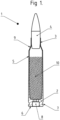
- the in Fig. 1 The cartridge 1 shown has a cartridge case 2 and a projectile 4, which is designed as a hard core projectile and is inserted into the narrowed neck 3 of the cartridge case.
- the cartridge case 2 has a conical base body 5 with a foot 6 formed thereon, which contains an extraction groove 7 and a primer cap 8 embedded in it.
- the cartridge case 2 has a frustoconical shoulder 9 which forms a connection between the conical base body 5 and the narrowed neck 3 of the cartridge case 2 .
- a propellant charge 10 consisting of nitrocellulose powder.
- the projectile 4 that can be seen in the figure essentially consists of three parts, namely a jacket 11 that determines the outer and inner ballistic shape, a hard core 12 encased in this jacket 11 , and a carrier or shoe 13 that holds the core 12 within the jacket 11 , which has a certain mass and is adapted in its outer shape to the shape of the jacket and, on the other hand, in its open part 13a , like a quiver or in the shape of a shoe, receives the hard core 12 and holds it within the projectile.
- the mass of the shoe 13 supports the penetrating energy or penetrating power of the hard core 12 when it hits a hard target such as an armored target.
- the shoe 13 has a foot 13b made of solid material, the outer contour of which is adapted to the ballistic shape of the jacket 11 of the projectile 4 in order to ensure that the shoe 13 fits securely in the projectile 4.
- a blind hole is machined or formed into the carrier 13 from the front or outer end, which forms the open part 13a for the snug fit of the rear end of the hard core 12.
- the shoe 13 thus forms a circumferential, raised collar as a lateral support for the hard core 12 inserted into the shoe 13 .
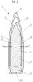
- the core 12 which is made of particularly hard material such as hard metal, tungsten carbide or sintered material, has a cylindrical base body 18, which with its rear end inside the collar 17 in the open part 13a of the shoe 13. This base body 18 passes over an angular shoulder 19 into a sharp point 20 , which forms the front end of the core 12.
- This point 20 is at a distance from the outer rounded point-shaped end 21 of the jacket 11 and only touches this end when the jacket 11 of the projectile 4 is deformed when it hits a hard target.
- Fig. 2 As can be seen, in the undeformed projectile 4 there is a cavity between the sharp tip 20 of the hard core 12 and the outer end 21 of the jacket 11 of the projectile, which extends into the area of the shoulder 19 of the core 12, which rests against the inner wall of the jacket 11. On the other side of the shoulder 19 there is a further cavity 23 between the core 12 and the jacket 11 , which extends into the area of the raised collar 17 of the carrier 13 .
- the outer end 21 of the jacket 11 is pushed inwards towards the sharp tip 20 of the hard core 12 and is thereby deformed.
- the hard core 12 is pushed forward towards the outer end 21 of the jacket 11.
- the angled shoulder 19 resting on the jacket 11 tears open the jacket 11.
- the tip 20 hits the outer end 21 of the jacket 11 , the jacket 11 is also torn open here.
- the hard core 12, which is virtually non-deformable penetrates the hard target and penetrates it with high precision.
- the mass of the shoe 13 supports the penetrating movement or penetrating energy of the core 12 when penetrating the target and when penetrating the hard target. Since the core 12 practically does not deform, precise hits and smooth penetrations are achieved.
- Fig. 3 shows a cross-section through the projectile 4 at the level of the open part 13a of the shoe 13.
- the shoe 13 is inserted and held in the projectile jacket 11 .
- the hard core is inserted in the collar of the open part 13a of the shoe 13.
- the core 12 does not lie on the inner cross section 14a, 14b of the open part 13a of the shoe all the way around the circumference of the open part. Sections alternate in the direction of the circumference in which the inner cross section 14b lies on the hard core 12 and the inner cross section 14a is spaced from the hard core 12.
- the core 12 is held by three adjacent sections 14b and thus centered in the shoe 13.
- the other sections, in which the inner cross-section 14a is spaced from the hard core 12 and thereby encloses a free space 15 enable the jacket material to be absorbed, which is displaced into the fields and grooves of the barrel when the bullet is crushed.
Landscapes
- Engineering & Computer Science (AREA)
- Chemical & Material Sciences (AREA)
- Combustion & Propulsion (AREA)
- General Engineering & Computer Science (AREA)
- Footwear And Its Accessory, Manufacturing Method And Apparatuses (AREA)
Claims (15)
- Projectile pour une cartouche d'arme à feu portative, destiné à être inséré dans le col d'une douille de cartouche d'une cartouche, dans lequelle projectile (4) présente une enveloppe (11), un noyau dur (12) disposé dans l'enveloppe et un support maintenant le noyau dur dans l'enveloppe ;le support est conçu comme un sabot (13) ;le sabot est disposé dans la partie arrière du projectile ;le sabot (13) présente une partie ouverte (13a) orientée vers l'avant, dans laquelle est inséré le noyau dur (12),caractérisé en ce quela section transversale intérieure (14a, 14b) de la partie ouverte (13a) du sabot, vue dans le sens de la circonférence de la section transversale, est alternativement appliquée par sections contre le noyau dur (12) et est espacée du noyau dur (12).
- Projectile selon la revendication 1, caractérisé en ce qu'il existe un espace libre (15) où la section transversale interne (14a) de la partie ouverte (13a) du sabot (13) est espacée du noyau dur (12).
- Projectile selon la revendication 1 ou 2, caractérisé en ce que les sections à lesquelles la section transversale interne (14a, 14b) de la partie ouverte du sabot, vue dans le sens de la circonférence de la section transversale, alternativement s'appliquent par sections contre le noyau dur et sont espacées du noyau dur, sont réparties uniformément et de préférence trois ou quatre sections sont prévues où la section transversale interne est appliquée contre le noyau.
- Projectile selon l'une des revendications précédentes, caractérisé en ce que la section transversale interne (14a, 14b) de la partie ouverte du sabot est sensiblement circulaire, mais avec des rayons de section transversale variables (Rmax, Rmin), dans lequel le rayon de section transversale le plus petit (Rmin) est présent là où la section transversale (14b) s'applique contre le noyau dur (12) et le rayon de section transversale maximal (Rmax) est présent là où la section transversale est espacée au maximum du noyau dur.
- Projectile selon l'une des revendications précédentes, caractérisé en ce que le sabot (13) est configuré pour recevoir l'extrémité arrière du noyau dur (12) du projectile.
- Projectile selon l'une des revendications précédentes, caractérisé en ce que la section transversale externe (16) du sabot est circulaire.
- Projectile selon l'une des revendications précédentes, caractérisé en ce que la forme extérieure du sabot est adaptée à l'enveloppe (11) du projectile (4) dans la partie arrière de celui-ci.
- Projectile selon l'une des revendications précédentes, caractérisé en ce que le noyau dur (12) du projectile (4) est constitué d'acier ou d'un matériau très solide qui, en raison de ses propriétés, résiste aux sollicitations mécaniques, telles que notamment la flexion, la traction, la compression, le cisaillement, jusqu'à la limite de charge avant qu'il n'y ait défaillance, notamment des matériaux frittés, des métaux lourds, du carbure de tungstène, du métal dur ou de l'acier trempé.
- Projectile selon l'une des revendications précédentes, caractérisé en ce que l'enveloppe (11) du projectile (4) est constituée de cuivre, d'acier, de bronze ou de tombac.
- Projectile selon l'une des revendications précédentes, caractérisé en ce que le sabot (13) est une pièce pressée, de préférence en un matériau métallique ductile tel que le cuivre, un alliage de cuivre, le tombac, le laiton ou un métal d'aluminium ou un alliage d'aluminium approprié.
- Projectile selon l'une des revendications précédentes, caractérisé en ce que la forme extérieure du sabot (13), à l'exception de son arrière (13b), est un cylindre, qui est de préférence dépourvu de rainures de décharge périphériques à la périphérie extérieure.
- Projectile selon l'une des revendications précédentes, caractérisé en ce que le noyau dur (12) du projectile (4) présente une tige cylindrique (18) s'adaptant dans la partie ouverte (13a) du sabot (13), un épaulement coudé (19) s'appliquant ponctuellement contre l'enveloppe (11) par l'intérieur, ainsi qu'une pointe acérée (20) située à distance de l'extrémité avant extérieure (21) de l'enveloppe (11).
- Cartouche pour arme à feu portative, avec une douille de cartouche munie d'une amorce et contenant une charge propulsive, ainsi qu'un projectile (4) inséré dans le col de la douille de cartouche selon l'une des revendications précédentes.
- Procédé de fabrication d'un projectile pour une cartouche d'un particulier calibre présentant les caractéristiques de l'une des revendications précédentes 1 à 12, comprenant les étapes suivantes :- fournir une pluralité d'enveloppes (11) du calibre particulier, de poids différents, en matériaux de poids différents, toutes les enveloppes ayant la même forme et la même taille ;- fournir une pluralité de sabots (13) du calibre particulier, de poids différents, en matériaux de poids différents, tous les sabots ayant la même forme et la même taille ;- fournir une pluralité de noyaux durs (12) du calibre particulier, de poids différents, en matériaux de poids différents, dans lequel tous les sabots- - présentent la même forme et la même taille au moins dans la zone du noyau qui est insérée dans la partie ouverte (13a) du sabot ;- - et sont ajustés dans l'espace vide fourni par les enveloppes entre le sabot et l'enveloppe ;- sélectionner un noyau du calibre particulier ;- déterminer une enveloppe adaptée au noyau sélectionné du calibre particulier, et au sabot du calibre particulier de manière à respecter une plage de poids de projectile prédéterminée du calibre particulier ;- assembler un projectile à partir du noyau, de l'enveloppe et du sabot sélectionnés.
- Procédé selon la revendication 14, dans lequel la pluralité de sabots et d'enveloppes est fabriquée sur la même machine ou sur une machine similaire avec les mêmes outils ou des outils similaires.
Applications Claiming Priority (1)
| Application Number | Priority Date | Filing Date | Title |
|---|---|---|---|
| DE102022205242.0A DE102022205242B4 (de) | 2022-05-25 | 2022-05-25 | Geschoss für eine Patrone für Handfeuerwaffen mit hartem Kern, sowie Verfahren zu dessen Herstellung |
Publications (3)
| Publication Number | Publication Date |
|---|---|
| EP4283244A1 EP4283244A1 (fr) | 2023-11-29 |
| EP4283244C0 EP4283244C0 (fr) | 2024-11-13 |
| EP4283244B1 true EP4283244B1 (fr) | 2024-11-13 |
Family
ID=86497662
Family Applications (1)
| Application Number | Title | Priority Date | Filing Date |
|---|---|---|---|
| EP23174473.1A Active EP4283244B1 (fr) | 2022-05-25 | 2023-05-22 | Projectile pour cartouche d'arme à feu portative à noyau dur et son procédé de fabrication |
Country Status (2)
| Country | Link |
|---|---|
| EP (1) | EP4283244B1 (fr) |
| DE (1) | DE102022205242B4 (fr) |
Citations (1)
| Publication number | Priority date | Publication date | Assignee | Title |
|---|---|---|---|---|
| EP0895572B1 (fr) * | 1996-04-26 | 2002-07-03 | Bofors Vanäsverken AB | Obus de petit calibre |
Family Cites Families (6)
| Publication number | Priority date | Publication date | Assignee | Title |
|---|---|---|---|---|
| GB592538A (en) | 1941-12-22 | 1947-09-22 | Lumalampan Ab | Improvements in projectiles of small calibre |
| GB601686A (en) | 1942-02-27 | 1948-05-11 | Lumalampan Ab | Improvements in and relating to projectiles |
| DE19710113A1 (de) | 1997-03-12 | 1998-09-17 | Elisenhuette Metallwerk | Patrone für Handfeuerwaffen |
| FR2774162A1 (fr) | 1998-01-28 | 1999-07-30 | Anthena Soc | Projectile a guide conique polygonal pour arme a feu a canon raye, et munition comportant un tel projectile |
| RS51099B (sr) | 2004-05-11 | 2010-10-31 | Ruag Ammotec Ag. | Bezolovni projektil |
| US10081057B2 (en) * | 2010-11-10 | 2018-09-25 | True Velocity, Inc. | Method of making a projectile by metal injection molding |
-
2022
- 2022-05-25 DE DE102022205242.0A patent/DE102022205242B4/de active Active
-
2023
- 2023-05-22 EP EP23174473.1A patent/EP4283244B1/fr active Active
Patent Citations (1)
| Publication number | Priority date | Publication date | Assignee | Title |
|---|---|---|---|---|
| EP0895572B1 (fr) * | 1996-04-26 | 2002-07-03 | Bofors Vanäsverken AB | Obus de petit calibre |
Also Published As
| Publication number | Publication date |
|---|---|
| DE102022205242A1 (de) | 2023-11-30 |
| EP4283244C0 (fr) | 2024-11-13 |
| EP4283244A1 (fr) | 2023-11-29 |
| DE102022205242B4 (de) | 2024-02-15 |
Similar Documents
| Publication | Publication Date | Title |
|---|---|---|
| EP0428561B1 (fr) | Balle | |
| DE202022102887U1 (de) | Geschoss für eine Patrone für Handfeuerwaffen mit hartem Kerrn | |
| DE102020133371B4 (de) | Vollmantelgeschoss und Verfahren zum Herstellen eines Vollmantelgeschosses | |
| EP1285218B1 (fr) | Projectile a deformation partielle de petit calibre et procede permettant de le produire | |
| WO1990005891A1 (fr) | Projectile deformable, munition equipee de celui-ci, ainsi que procede de fabrication dudit projectile | |
| DE2905797C2 (fr) | ||
| EP2498045B1 (fr) | Projectile pour cartouches d'exercice | |
| EP4038339A1 (fr) | Pénétrateur, utilisation d'un pénétrateur et projectile | |
| EP3514479B1 (fr) | Projectile à usage multiple | |
| EP4283245A1 (fr) | Outil et procédé de fabrication d'un projectile et projectile | |
| EP4283244B1 (fr) | Projectile pour cartouche d'arme à feu portative à noyau dur et son procédé de fabrication | |
| DE102004035385A1 (de) | Teilzerlegungsgeschoss mit massivem Kern und Kern aus gepresstem Pulver | |
| WO2024047034A1 (fr) | Projectile exerçant une contrainte réduite sur le canon | |
| DE60021093T2 (de) | Aus gesintertem pulver hergestelltes geschoss | |
| EP3638974B1 (fr) | Procédé de fabrication d'un projectile de petit calibre, projectile de petit calibre et munition de petit calibre contenant un tel projectile de petit calibre | |
| WO2023161400A1 (fr) | Intermédiaire, outil et procédé de fabrication d'un projectile à déformation ayant une balistique finale définie | |
| DE102005039901B4 (de) | Geschoss, insbesondere für Mittelkalibermunition | |
| EP4298397A1 (fr) | Balle à déformation pour munition pour police et autres corps exécutifs | |
| EP4428481A1 (fr) | Projectile à enveloppe | |
| DE102018119165B3 (de) | Vollmantelgeschoß mit Kernen | |
| DE19710113A1 (de) | Patrone für Handfeuerwaffen | |
| DE29723236U1 (de) | Patrone für Handfeuerwaffen | |
| WO2026052867A1 (fr) | Projectile de pénétrateur à chemise métallique complète | |
| EP4428482A1 (fr) | Projectile à enveloppe | |
| DE29705546U1 (de) | Patrone für Handfeuerwaffen |
Legal Events
| Date | Code | Title | Description |
|---|---|---|---|
| PUAI | Public reference made under article 153(3) epc to a published international application that has entered the european phase |
Free format text: ORIGINAL CODE: 0009012 |
|
| STAA | Information on the status of an ep patent application or granted ep patent |
Free format text: STATUS: THE APPLICATION HAS BEEN PUBLISHED |
|
| AK | Designated contracting states |
Kind code of ref document: A1 Designated state(s): AL AT BE BG CH CY CZ DE DK EE ES FI FR GB GR HR HU IE IS IT LI LT LU LV MC ME MK MT NL NO PL PT RO RS SE SI SK SM TR |
|
| STAA | Information on the status of an ep patent application or granted ep patent |
Free format text: STATUS: REQUEST FOR EXAMINATION WAS MADE |
|
| 17P | Request for examination filed |
Effective date: 20240429 |
|
| RBV | Designated contracting states (corrected) |
Designated state(s): AL AT BE BG CH CY CZ DE DK EE ES FI FR GB GR HR HU IE IS IT LI LT LU LV MC ME MK MT NL NO PL PT RO RS SE SI SK SM TR |
|
| GRAJ | Information related to disapproval of communication of intention to grant by the applicant or resumption of examination proceedings by the epo deleted |
Free format text: ORIGINAL CODE: EPIDOSDIGR1 |
|
| STAA | Information on the status of an ep patent application or granted ep patent |
Free format text: STATUS: GRANT OF PATENT IS INTENDED |
|
| GRAP | Despatch of communication of intention to grant a patent |
Free format text: ORIGINAL CODE: EPIDOSNIGR1 |
|
| INTG | Intention to grant announced |
Effective date: 20240619 |
|
| RAP3 | Party data changed (applicant data changed or rights of an application transferred) |
Owner name: METALLWERK ELISENHUETTE GMBH |
|
| GRAS | Grant fee paid |
Free format text: ORIGINAL CODE: EPIDOSNIGR3 |
|
| GRAA | (expected) grant |
Free format text: ORIGINAL CODE: 0009210 |
|
| STAA | Information on the status of an ep patent application or granted ep patent |
Free format text: STATUS: THE PATENT HAS BEEN GRANTED |
|
| AK | Designated contracting states |
Kind code of ref document: B1 Designated state(s): AL AT BE BG CH CY CZ DE DK EE ES FI FR GB GR HR HU IE IS IT LI LT LU LV MC ME MK MT NL NO PL PT RO RS SE SI SK SM TR |
|
| REG | Reference to a national code |
Ref country code: GB Ref legal event code: FG4D Free format text: NOT ENGLISH |
|
| REG | Reference to a national code |
Ref country code: CH Ref legal event code: EP |
|
| REG | Reference to a national code |
Ref country code: IE Ref legal event code: FG4D Free format text: LANGUAGE OF EP DOCUMENT: GERMAN |
|
| REG | Reference to a national code |
Ref country code: DE Ref legal event code: R096 Ref document number: 502023000293 Country of ref document: DE |
|
| U01 | Request for unitary effect filed |
Effective date: 20241121 |
|
| U07 | Unitary effect registered |
Designated state(s): AT BE BG DE DK EE FI FR IT LT LU LV MT NL PT RO SE SI Effective date: 20241127 |
|
| PG25 | Lapsed in a contracting state [announced via postgrant information from national office to epo] |
Ref country code: HR Free format text: LAPSE BECAUSE OF FAILURE TO SUBMIT A TRANSLATION OF THE DESCRIPTION OR TO PAY THE FEE WITHIN THE PRESCRIBED TIME-LIMIT Effective date: 20241113 Ref country code: IS Free format text: LAPSE BECAUSE OF FAILURE TO SUBMIT A TRANSLATION OF THE DESCRIPTION OR TO PAY THE FEE WITHIN THE PRESCRIBED TIME-LIMIT Effective date: 20250313 |
|
| PG25 | Lapsed in a contracting state [announced via postgrant information from national office to epo] |
Ref country code: ES Free format text: LAPSE BECAUSE OF FAILURE TO SUBMIT A TRANSLATION OF THE DESCRIPTION OR TO PAY THE FEE WITHIN THE PRESCRIBED TIME-LIMIT Effective date: 20241113 |
|
| PG25 | Lapsed in a contracting state [announced via postgrant information from national office to epo] |
Ref country code: NO Free format text: LAPSE BECAUSE OF FAILURE TO SUBMIT A TRANSLATION OF THE DESCRIPTION OR TO PAY THE FEE WITHIN THE PRESCRIBED TIME-LIMIT Effective date: 20250213 |
|
| PG25 | Lapsed in a contracting state [announced via postgrant information from national office to epo] |
Ref country code: GR Free format text: LAPSE BECAUSE OF FAILURE TO SUBMIT A TRANSLATION OF THE DESCRIPTION OR TO PAY THE FEE WITHIN THE PRESCRIBED TIME-LIMIT Effective date: 20250214 |
|
| PG25 | Lapsed in a contracting state [announced via postgrant information from national office to epo] |
Ref country code: PL Free format text: LAPSE BECAUSE OF FAILURE TO SUBMIT A TRANSLATION OF THE DESCRIPTION OR TO PAY THE FEE WITHIN THE PRESCRIBED TIME-LIMIT Effective date: 20241113 |
|
| PG25 | Lapsed in a contracting state [announced via postgrant information from national office to epo] |
Ref country code: RS Free format text: LAPSE BECAUSE OF FAILURE TO SUBMIT A TRANSLATION OF THE DESCRIPTION OR TO PAY THE FEE WITHIN THE PRESCRIBED TIME-LIMIT Effective date: 20250213 |
|
| U20 | Renewal fee for the european patent with unitary effect paid |
Year of fee payment: 3 Effective date: 20250526 |
|
| PG25 | Lapsed in a contracting state [announced via postgrant information from national office to epo] |
Ref country code: SM Free format text: LAPSE BECAUSE OF FAILURE TO SUBMIT A TRANSLATION OF THE DESCRIPTION OR TO PAY THE FEE WITHIN THE PRESCRIBED TIME-LIMIT Effective date: 20241113 |
|
| PG25 | Lapsed in a contracting state [announced via postgrant information from national office to epo] |
Ref country code: SK Free format text: LAPSE BECAUSE OF FAILURE TO SUBMIT A TRANSLATION OF THE DESCRIPTION OR TO PAY THE FEE WITHIN THE PRESCRIBED TIME-LIMIT Effective date: 20241113 |
|
| PG25 | Lapsed in a contracting state [announced via postgrant information from national office to epo] |
Ref country code: CZ Free format text: LAPSE BECAUSE OF FAILURE TO SUBMIT A TRANSLATION OF THE DESCRIPTION OR TO PAY THE FEE WITHIN THE PRESCRIBED TIME-LIMIT Effective date: 20241113 |
|
| PLBE | No opposition filed within time limit |
Free format text: ORIGINAL CODE: 0009261 |
|
| STAA | Information on the status of an ep patent application or granted ep patent |
Free format text: STATUS: NO OPPOSITION FILED WITHIN TIME LIMIT |
|
| 26N | No opposition filed |
Effective date: 20250814 |
|
| PG25 | Lapsed in a contracting state [announced via postgrant information from national office to epo] |
Ref country code: MC Free format text: LAPSE BECAUSE OF FAILURE TO SUBMIT A TRANSLATION OF THE DESCRIPTION OR TO PAY THE FEE WITHIN THE PRESCRIBED TIME-LIMIT Effective date: 20241113 |
|
| PG25 | Lapsed in a contracting state [announced via postgrant information from national office to epo] |
Ref country code: IE Free format text: LAPSE BECAUSE OF NON-PAYMENT OF DUE FEES Effective date: 20250522 |