EP0895588B1 - Dispositif pour l'investigation - Google Patents
Dispositif pour l'investigation Download PDFInfo
- Publication number
- EP0895588B1 EP0895588B1 EP97921674A EP97921674A EP0895588B1 EP 0895588 B1 EP0895588 B1 EP 0895588B1 EP 97921674 A EP97921674 A EP 97921674A EP 97921674 A EP97921674 A EP 97921674A EP 0895588 B1 EP0895588 B1 EP 0895588B1
- Authority
- EP
- European Patent Office
- Prior art keywords
- light
- sample
- probe
- signal
- detector
- Prior art date
- Legal status (The legal status is an assumption and is not a legal conclusion. Google has not performed a legal analysis and makes no representation as to the accuracy of the status listed.)
- Expired - Lifetime
Links
- 238000011835 investigation Methods 0.000 title claims description 7
- 239000000523 sample Substances 0.000 claims description 99
- 238000005259 measurement Methods 0.000 claims description 21
- 239000000835 fiber Substances 0.000 claims description 16
- 230000008878 coupling Effects 0.000 claims description 9
- 238000010168 coupling process Methods 0.000 claims description 9
- 238000005859 coupling reaction Methods 0.000 claims description 9
- 238000001514 detection method Methods 0.000 claims description 4
- 238000005286 illumination Methods 0.000 claims 5
- 238000006243 chemical reaction Methods 0.000 description 11
- 238000004458 analytical method Methods 0.000 description 6
- 230000003993 interaction Effects 0.000 description 5
- 239000013307 optical fiber Substances 0.000 description 5
- 238000012937 correction Methods 0.000 description 4
- 238000000034 method Methods 0.000 description 4
- 230000003287 optical effect Effects 0.000 description 4
- 230000008569 process Effects 0.000 description 4
- 238000001311 chemical methods and process Methods 0.000 description 3
- 239000004020 conductor Substances 0.000 description 3
- 238000012545 processing Methods 0.000 description 3
- 238000012360 testing method Methods 0.000 description 3
- 239000003795 chemical substances by application Substances 0.000 description 2
- 238000013461 design Methods 0.000 description 2
- 230000005670 electromagnetic radiation Effects 0.000 description 2
- 238000001228 spectrum Methods 0.000 description 2
- 238000012935 Averaging Methods 0.000 description 1
- 230000005540 biological transmission Effects 0.000 description 1
- 230000015572 biosynthetic process Effects 0.000 description 1
- 230000001186 cumulative effect Effects 0.000 description 1
- 230000003111 delayed effect Effects 0.000 description 1
- 230000001419 dependent effect Effects 0.000 description 1
- 238000010586 diagram Methods 0.000 description 1
- 238000005516 engineering process Methods 0.000 description 1
- 238000011156 evaluation Methods 0.000 description 1
- 229910052736 halogen Inorganic materials 0.000 description 1
- 150000002367 halogens Chemical class 0.000 description 1
- 238000007654 immersion Methods 0.000 description 1
- 230000001771 impaired effect Effects 0.000 description 1
- 239000012535 impurity Substances 0.000 description 1
- 230000010365 information processing Effects 0.000 description 1
- 238000007689 inspection Methods 0.000 description 1
- 238000012544 monitoring process Methods 0.000 description 1
- 230000005855 radiation Effects 0.000 description 1
- 230000009467 reduction Effects 0.000 description 1
- 239000007787 solid Substances 0.000 description 1
- 230000003595 spectral effect Effects 0.000 description 1
- 230000002123 temporal effect Effects 0.000 description 1
- 230000007704 transition Effects 0.000 description 1
- 230000003313 weakening effect Effects 0.000 description 1
Images

Classifications
-
- G—PHYSICS
- G01—MEASURING; TESTING
- G01N—INVESTIGATING OR ANALYSING MATERIALS BY DETERMINING THEIR CHEMICAL OR PHYSICAL PROPERTIES
- G01N21/00—Investigating or analysing materials by the use of optical means, i.e. using sub-millimetre waves, infrared, visible or ultraviolet light
- G01N21/17—Systems in which incident light is modified in accordance with the properties of the material investigated
- G01N21/25—Colour; Spectral properties, i.e. comparison of effect of material on the light at two or more different wavelengths or wavelength bands
- G01N21/251—Colorimeters; Construction thereof
- G01N21/253—Colorimeters; Construction thereof for batch operation, i.e. multisample apparatus
Definitions
- the invention relates to a device with which Examination of several sample room areas and / or several Sample rooms Distributed sample signals and recorded analysis signals and in particular a device with the features according to the preamble of claim 1.
- a chemical reaction between several components monitor in a reaction vessel.
- the Analysis of the components to be monitored based on their Interaction with electromagnetic radiation (in particular visible range and adjacent wavelengths, d. H. UV / VIS, NIR, IR).
- the electromagnetic radiation is called Sample signal led into the reaction vessel, there through the Interaction changed in a characteristic way and as Analysis signal (or probe signal) to a measuring device recycled.
- Probe 204 can be used with this (and with all described below Applications) e.g. by an immersion probe (transmission probe, ATR probe, reflection probe, transflexion probe or the like.) be formed. Then after the interaction spectrally and intensively changed light (analysis or Probe signal) via the light guide (205) to the decoupling point 206 out and from there to a detector element (not shown) of the detector means 40 is blasted.
- the arrangement has a reference channel 30, in which Light from the light source 10 without the intermediary of a light guide to the same or another detector element (not shown) of the detector means 40 is blasted to To detect fluctuations in lamp parameters and at Evaluation of the analysis signal to be considered.
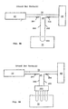
- the system shown in Fig. 6A has the following disadvantages.
- the reaction vessel 50 has such a large volume that there are spatial inhomogeneities in the course of the reaction can form, so that that determined with the probe 204 Test result not necessarily for the whole Reaction vessel is representative. Furthermore, impurities or errors on probe 204 for unnoticed error results to lead.
- the known distributor device 203 works according to one Multiplexer principle. That is, the different channels (a-c) can be driven at different times by the sample signal light guide 202 step by step with each of the channels is connected. This coupling is staggered in time traditionally by mechanical means.
- the system of Figure 6B has the following disadvantages. Due to the staggered measurement, it is not possible simultaneous results for all investigation channels receive. This means that the measured values cannot be read easily be compared. The investigation requires through that mechanical switching to the different examination channels a-c relatively much time. The pursuit of Process sequences of fast reactions are difficult or impossible. There are also high demands on the Adjustment of the movable ones provided in the distributor 203 optical parts. It also happens when the system is operating 6B to wear and tear, the operational readiness restrict and increase costs. Finally is the reproducibility of the measurement results by the Movement of the light guide is impaired.
- FIGS. 6A and 6B are not limited to applications in chemical process engineering.
- the uses for other physical-technical measuring tasks however, have the same problems and disadvantages connected as stated above.
- An important idea of the invention is an examination system to create that in terms of measurement reading represents a real multi-channel system.
- a distribution means or: light coupler
- the sample signal or: sample light
- illuminant measuring light source
- a Variety of conductor means especially light guides
- the examination system according to the invention is preferably designed such that also in relation to the A real multichannel system is provided becomes.
- a detector means is divided into a number of Detector elements divided, each one of the plurality of conductor means (optical fibers) assigned to the probe signal is.
- Embodiments of the examination system according to the invention also provide for the establishment of a reference channel, with a variety of Detector elements corresponding to the large number of sample or Probe light guides is provided. So it will the multi-channel principle also applied to the reference channel.
- the invention Examination system through a spectrophotometer formed to study a variety of sample rooms the measuring channel is divided into a large number of individual channels is, sample light with a light coupler at the same time in a variety of light guides that probe into the Conduct rehearsal rooms, can be coupled in, and after that Interaction of the sample light with the samples changed Analytical light as probe light with a large number of light guides to a corresponding number of detector elements is feasible.
- This spectrophotometer is also with a Provide reference channel, which is an alternative to the measuring channel is operable and a variety of reference light guides includes in the reference light at the same time with a light coupler can be coupled in and each correspondingly as a reference means used for the variety of detector elements become.
- the embodiments of the examination system according to the invention (especially the spectrophotometer) different types of light couplers such as a fiber coupler, a plate coupler, a bundle coupler or a mirror coupler in front.
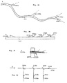
- FIG. 1 and 2 as a schematic diagram Examination devices each include one Illuminant 10 (or: light source 10), a measuring channel 20, a reference channel 30 and a detector means 40 Make solid lines of the measuring and reference channels on the one hand light paths with free radiation propagation from the Light source 10 each to the light coupler 210 or to the light coupler 310 or the detector element 402 and otherwise in Guide means (light guides) are guided light paths
- Figures show an example of the structure of the examination system with 3 single channels, i.e. with a three-channel Measuring channel and possibly a three-channel reference channel.
- Measuring channel 20 contains a distribution means (or: light coupler) 210 with which the measuring light emanating from the light source 10 (Sample signal) simultaneously in three light guides (sample signal light guide) 202a-c is coupled, each to probes 204a-c, which in the sample or reaction space 50 are arranged.
- a second leads from probes 204a-c Group of light guides 205a-c (probe signal light guide) the detector means 40, where that after interaction in the Sample space 50 modified measuring light (probe signal) each the optical fibers are coupled out and detector elements 401a-c is detected.
- the reference channel 30 is either by a direct Light path through the air from light source 10 to one Reference detector element 402 (see FIG. 1) or according to the invention by a Multi-channel arrangement (see FIG. 2) is formed. With the multi-channel arrangement becomes the reference light emanating from the light source 10 through a light coupler 310 to the reference light guide 311a-c distributed and each to one of the detector elements 401a-c led the probe signals of the measuring channel 20 capture.
- the reference signal is in the first embodiment (Fig. 1) taken into account by the Probe signal detectors 401a-c recorded measured values with electronic Averaging based on that with the reference detector 402 recorded reference value can be compared. According to In the second embodiment (FIG.
- this signal correction takes place on each probe signal detector 401a-c by this is alternately irradiated with the reference or measuring light.
- distribution means (or light coupler) 210, 310 are the in 3A-c schematically illustrated designs conceivable.
- the first design (Fig. 3A) represents a fiber coupler, such as he basically from the signal line in information processing is known.
- On an optical fiber 211 a variety by means of a suitable melt-pull process attached by light guides 202a-d onto which the in the Fiber 211 light coupled in the direction of arrow A. to be led.
- the light guides 202a-d (in this case: Distribution over four light guides) then lead the measuring light in the sample space 50 (see FIGS. 1, 2).
- FIG. 3B Another example is the plate coupler (See Fig. 3B), in which the measuring or reference light in Direction of arrow A over a wedge in a light guide plate 212 is coupled.
- this plate 212 that is Total reflection light up to the decoupling wedges 213a-c performed, each connected to the light guides 202a-c are.
- distribution means according to the invention can preferably be realized by a Bundle coupler (see Fig. 3C) formed.
- a Bundle coupler see Fig. 3C
- distribution means according to the invention is a version in which the Ends of a plurality of light guides are folded together in this way and arranged that a common bundle face is formed, on which the measuring or reference light is projectable. This bundle face is preferably in essentially flat and polished.
- each light guide is one separate mono-mode fiber, each one measuring or Reference channel is assigned.
- each measurement and / or reference channel a large number of fine optical fibers assigned to form the said bundle end face split (disassembled) and homogeneously distributed with the fiber ends of the remaining channels.
- each one Channel are assigned to the bundle face Lighting fluctuations (e.g. spiral movements of the light source) balanced.
- the fiber ends are distributed evenly on a surface that is about the lighting spot corresponds to the light source.
- a transition piece for each channel may be provided on which the fine Fibers coupled from the coupler end to a mono-mode fiber with which the distance to the measuring location (probe) is bridged can be.
- the total bundle of fiber ends is preferred in terms of the beam path of the light source 10 Light aligned so that the bundle axis with the optical Axis of the beam path coincides.
- the number of in a bundle of light guides combined is technical Requirements of the respective examination system adapt and can, for example, two to eight but also include more light guides.
- the bundle coupler is both in the Can be used in the measuring channel as well as in the reference channel.
- FIG. 3D Another example of a distribution means shown in Fig. 3D.
- the mirror coupler that keeps from the light source 10 in the direction of arrow A led light on a variety of semi-transparent mirrors 214a-c, in to which a part of the measuring light is separated and sent to the Positions 215a-d in the light guides 202a-d (in this case four light guides).
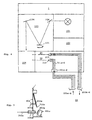
- FIG. 4 shows schematically an implementation of the invention Examination device as a 4-channel spectrophotometer.
- the components shown are advantageously in one shared housing that the basic unit of the Spectrophotometer represents.
- the illuminant (or the light source) 10 (see FIGS. 1, 2) is replaced by a stabilized power supply 102 operated lamp (e.g. halogen lamp) 101, the monochromator 103 and the channel selection means 106 educated.
- the monochromator 103 can e.g. through a Grid monochromator are formed, in which the of the Lamp 101 outgoing light through a mirror 104 on the pivotable grating 105 directed and a generated by this Diffraction order with the second mirror 104 in the channel selection means 106 is steered.
- the Measuring light is collimated on the distribution means (or light coupler) 210 or 310 steered corresponding to one of the above described distribution means can be formed.
- Light couplers 210 guide light guides 202a-d to (not shown) probes in the sample space 50, of which in turn light guides 205a-d to the detector elements in the basic device 401a-d. From the light coupler 310, the Light guides 311a-d in the basic device to the respective detector elements 401a-d. The measurement and reference light acquisition on each the detector elements will be described below with reference to FIG. 5 explained.
- the spectrophotometer constructed according to the invention is also provided with a control 1, in particular the Measuring and reference channel switching (channel selection means 106), the Monochromator drive and the measurement recording is controllable.
- the optical components of the spectrophotometer in particular the components for coupling the measuring light into the light guide, are preferably dampened to vibration a common, massive support.
- the detector elements 401a-d shown schematically in FIG can e.g. on a side wall of the basic photometer to be appropriate. This is the example of an individual Detector element 401a as a schematic side view in Fig. 5 shown enlarged.
- the detector element 401a is on the inside of the housing a side wall 406 (e.g. the front side wall) and attached protected from residual light.
- the one from the Optical fiber 202a introduced in the sample space through a coupling insert 206 (e.g. SMA standard plug) in the housing wall 406 received such that the fiber end the detector surface has.
- the photosensitive surface of the Detector for example formed by a photodiode is at the aperture of the fiber end (e.g. aperture 0.22) customized.
- the Reference light guide 311a brought up to the detector element 401a.
- the reference light guide can be adjusted with an adjustable support 311a with respect to the detector area (voted).
- the edition consists of one on the Housing wall 406 attached resilient element 404a, the Inclination to the housing wall 406 by means of an adjusting screw 405a is changeable.
- the set screw 405a is on provided at one end with a hemispherical surface, that the resilient element 404 in any position of the set screw 405a has a clear bearing point and the Setting angle of the resilient element 404a in a defined manner depends on the position of the adjusting screw 405a.
- the function of the mechanically adjustable feeding of the Reference light guide 311a is that over the Reference channel 30 falling on the detector element 401a Light quantity to the light quantity measured in measuring channel 20 adapt. It is thus possible to use the detector element 401a for both measured value and reference value acquisition operate with the same gain so that the Measured value correction is optimized based on the reference value.
- the light quantity adjustment is carried out in that the Position of the reference light guide 311a with respect to the Detector area is adjusted so that only a part of the Available reference light is detected. Through this Detuning (or weakening) becomes a in the reference channel 30 Achieved reduction in the amount of light that the measurement light attenuation in Measuring channel 20 corresponds.
- a device 403a for optional introduction of filter elements can be provided, their function as an order filter explained below becomes.
- the spectrophotometer according to the invention according to the known principle of two-beam measurement operable that before the actual sample measurement with both a calibration measurement with the reference channel as well as with the measuring channel is performed against a known standard with which can be used to determine a control or correction line.
- This Correction line can be used when evaluating the following sample measurement be used to determine calibrated measured values.
- the sample space 50 becomes suitable Positions equipped with probes with the corresponding Light guides 202 and 205 are provided. After reaching one stable lamp operation becomes a preliminary measurement for adjustment the detector gain and to adjust the reference light guide position carried out. Then in all Channels recorded a reference light spectrum.
- This will the channel selection means 106 is set to the reference channel 30 and for reference value acquisition, the grating 105 of the monochromator 103 gradually adjusted over an angular range, which corresponds to the wavelength range under consideration.
- the channel selection means 106 is then applied to the measurement channel 20 provided so that the actual measured value acquisition can.
- the measured value acquisition driving through certain wavelength ranges
- simultaneously in all individual channels of the measuring channel 20 take place.
- the measured value acquisition can to track the course of the reaction over time or for a statistical processing can be repeated in quick succession. Depending on the achieved under the specific test conditions Lamp stability is between the individual measured value recordings the reference value acquisition is repeated.
- the examination device it is used as a spectrophotometer Function using order filters in the Devices 403a-d modified.
- the lighting device 10 can be operated such that not only one diffraction order of the monochromator grating, but more diffraction orders in the measuring and reference channels 20, 30 are coupled. Accordingly, the test probes 204 at the Scanning the monochromator supplied with sample light that each simultaneously through z. B. two wavelengths is formed. Wavelength separated around the probe signals at the detector elements 401 to be captured before selected the Detector elements 401 with devices 403 order filters attached, each one of the simultaneously supplied wavelengths suppress.
- the Invention does not have the same wavelength range in every probe channel detected. Rather, in the different channels for example, scanned two wavelength ranges simultaneously.
- the examination device can also be used as Spectrophotometer according to the invention by using a polychromatic sample lighting modified as follows become.
- the spectrophotometer is like this designed that the sample with polychromatic (white) light irradiated and this via the probes and the detector elements detected probe signal is recorded spectrally selectively.
- the probe signal in each sample channel of the Measuring channel 20 must be separated spectrally separately either each sample channel with a monochromator agent or one of all sample channels must be common Monochromator agent used may be provided, which then However, sample channel-specific is used selectively. This time-selective use of the common monochromator can by using a shutter or shutter be achieved.
- the closure means can either be at the end of the Probe conductors can be provided in order to detect each Sample channel when the other sample channels are closed allow or the closure means can before the entry Sample light can be provided in the sample light guide by the light coupling successively in only one the sample light guide takes place.
- the fiber ends in those shown in Fig. 3C Bundle coupler not directly adjacent to the formation arranged a closed coupling surface, but are spaced from each other.
- Operation of the spectrophotometer according to the invention with polychromatic sample lighting is such that initially with closed reference and measuring channels 20, 30 a Pure ambient light measurement takes place, the result of which is then at actual sample measurement as dark current from the spectra is removable.
- the examination device according to the invention has the following advantages.
- the measured value acquisition can be carried out in all individual channels done at the same time. With cumulative data acquisition the measuring accuracy increases and / or the temporal Reaction processes in the sample room run smoothly be followed. The measuring time is shortened considerably. Consequently can, for example, with four individual channels with one Scanning the reference value acquisition and using a Scan process the measured value acquisition take place, whereas with the conventional systems (e.g., as shown in Fig. 6B) to achieve a corresponding result, a total of eight scans of the monochromator would have to be carried out.
- the examination system according to the invention is regarding Number of individual channels in the context of common technical applications unlimited use.
- the number of individual channels can be easily adapted to the required application be adjusted. It is not necessary that the probes of the Individual channels within a sample room at different Positions attached wind. It is replaced by the easy to use detector control possible, also different To examine sample rooms at the same time.
Landscapes
- Physics & Mathematics (AREA)
- Spectroscopy & Molecular Physics (AREA)
- Health & Medical Sciences (AREA)
- Life Sciences & Earth Sciences (AREA)
- Chemical & Material Sciences (AREA)
- Analytical Chemistry (AREA)
- Biochemistry (AREA)
- General Health & Medical Sciences (AREA)
- General Physics & Mathematics (AREA)
- Immunology (AREA)
- Pathology (AREA)
- Investigating Or Analysing Materials By Optical Means (AREA)
Claims (9)
- Dispositif d'examen qui comprend :caractérisé parun moyen d'éclairage (10) pour produire un signal d'échantillon,un grand nombre de moyens conducteurs de signaux d'échantillon (202) pour guider le signal d'échantillon vers des moyens de sonde d'examen (204),des premiers moyens de distribution (210) pour l'introduction simultanée du signal d'échantillon dans les moyens conducteurs de signaux d'échantillon (202), etun moyen de détection (40) avec un grand nombre d'éléments de détection (401) qui sont prévus chacun pour détecter des signaux de sonde des moyens de sonde d'examen (204),un grand nombre de moyens conducteurs de signaux de sonde (205) pour guider des signaux de sonde, chacun, d'un moyen de sonde d'examen (204) vers l'un des éléments de détection (401), etun grand nombre de moyens conducteurs de signaux de référence (311) pour guider un signal de référence du moyen d'éclairage (10) vers chaque élément de détection (401), etun deuxième moyen de distribution (310) pour introduire simultanément le signal de référence dans chacun des moyens conducteurs de signaux de référence (311).
- Dispositif selon la revendication 1, dans lequel les moyens conducteurs de signaux de référence (311) sont disposés de manière qu'un signal de référence pouvant être synchronisé peut être détecté par chacun des éléments de détection (401).
- Dispositif selon la revendication 1 ou 2, dans lequel les moyens conducteurs de signaux d'échantillon, de signaux de sonde et de signaux de référence (202, 205, 311) sont formés chacun par des fibres optiques.
- Dispositif selon la revendication 3 dans lequel les premiers et/ou deuxièmes moyens de distribution (210, 310) sont formés par des coupleurs à guide optique (211), des coupleurs à plaque (212), des coupleurs à faisceau (213) ou des coupleurs à miroir (214).
- Photomètre spectral à plusieurs canaux qui contient un dispositif selon l'une des revendications 1 à 4.
- Photomètre spectral à plusieurs canaux selon la revendication 5, dans lequel le moyen d'éclairage est une source lumineuse (10) de spectre variable dont la lumière peut être introduite simultanément, en tant que signal d'échantillon, dans un grand nombre de guides optiques qui forment des canaux de mesure séparés, le premier moyen de distribution (210) comprenant un coupleur à faisceau (213) sur lequel les guides optiques sont disposés à la manière d'un faisceau, à leurs extrémités côté entrée, au moyen d'une monture, de manière que soit formée une surface frontale de faisceau sur laquelle le signal d'échantillon peut être projeté.
- Photomètre spectral à plusieurs canaux selon la revendication 6, dans lequel chaque guide optique est formé, dans la zone du moyen de distribution, par un grand nombre de fibres optiques, les extrémités des fibres étant disposées uniformément réparties sur la surface frontale de faisceau.
- Photomètre spectral à plusieurs canaux selon la revendication 6, dans lequel le moyen d'éclairage contient un monochromateur à grille (103) avec une grille de diffraction (105), et le signal d'échantillon comprend plusieurs ordres de diffraction de la grille à diffraction (105), un dispositif (403) étant prévu sur chaque élément de détection (402) du moyen de détection (40) pour l'introduction au choix d'un filtre d'ordre pour la détection sélective des signaux d'échantillon ou de référence conformément à un ordre de diffraction prédéterminé des ordres de diffraction du signal d'échantillon.
- Photomètre spectral à plusieurs canaux selon la revendication 5, dans lequel le moyen d'éclairage est une source lumineuse (10) polychrome et dans lequel les moyens de distribution (210, 310) et le moyen de détection (40) sont conçus pour la détection spectrale sélective des signaux.
Applications Claiming Priority (3)
| Application Number | Priority Date | Filing Date | Title |
|---|---|---|---|
| DE19615957A DE19615957A1 (de) | 1996-04-22 | 1996-04-22 | Verteilervorrichtung |
| DE19615957 | 1996-04-22 | ||
| PCT/EP1997/001995 WO1997040364A1 (fr) | 1996-04-22 | 1997-04-21 | Dispositif de repartition |
Publications (2)
| Publication Number | Publication Date |
|---|---|
| EP0895588A1 EP0895588A1 (fr) | 1999-02-10 |
| EP0895588B1 true EP0895588B1 (fr) | 2003-07-09 |
Family
ID=7792054
Family Applications (1)
| Application Number | Title | Priority Date | Filing Date |
|---|---|---|---|
| EP97921674A Expired - Lifetime EP0895588B1 (fr) | 1996-04-22 | 1997-04-21 | Dispositif pour l'investigation |
Country Status (4)
| Country | Link |
|---|---|
| EP (1) | EP0895588B1 (fr) |
| DE (2) | DE19615957A1 (fr) |
| DK (1) | DK0895588T3 (fr) |
| WO (1) | WO1997040364A1 (fr) |
Families Citing this family (3)
| Publication number | Priority date | Publication date | Assignee | Title |
|---|---|---|---|---|
| JP2003294609A (ja) * | 2002-03-29 | 2003-10-15 | Otsuka Denshi Co Ltd | 多点測定装置及び方法 |
| DE10222822A1 (de) * | 2002-05-21 | 2003-12-04 | Conducta Endress & Hauser | Online-Analysator |
| CN108120852B (zh) * | 2017-11-24 | 2020-03-20 | 清华大学 | 一种多探头分时复用装置、流速测量装置和方法 |
Family Cites Families (16)
| Publication number | Priority date | Publication date | Assignee | Title |
|---|---|---|---|---|
| FI44171B (fr) * | 1970-05-15 | 1971-06-01 | Ollituote Oy | |
| US3697185A (en) * | 1970-08-06 | 1972-10-10 | Technicon Instr | Method and apparatus for the time sharing of multiple channel analysis means |
| US3999062A (en) * | 1975-10-01 | 1976-12-21 | International Business Machines Corporation | Spectrophotometer for dual mode fluorescence analysis |
| JPS5970946A (ja) * | 1982-10-15 | 1984-04-21 | Toshiba Corp | 吸光度測定装置 |
| JPH0723896B2 (ja) * | 1984-01-10 | 1995-03-15 | オリンパス光学工業株式会社 | 化学分析装置 |
| FI843409A0 (fi) * | 1984-08-29 | 1984-08-29 | Labsystems Oy | Fluorometer. |
| NL8502138A (nl) * | 1985-07-26 | 1987-02-16 | Ekro Bv | Fiber-optische inrichting. |
| JPH01145552A (ja) * | 1987-12-02 | 1989-06-07 | Olympus Optical Co Ltd | 自動分析装置 |
| DE4116431A1 (de) * | 1991-05-18 | 1992-11-19 | Standard Elektrik Lorenz Ag | Optische messeinrichtung und verfahren zum betreiben der optischen messeinrichtung |
| JPH04348258A (ja) * | 1991-05-27 | 1992-12-03 | Kowa Co | 多チャンネル光学測定装置 |
| DE4128846C2 (de) * | 1991-08-30 | 1994-07-14 | Rainer Dr Klein | Integriert optischer Stoffsensor |
| US5210590A (en) * | 1992-02-18 | 1993-05-11 | L. T. Industries, Inc. | Rapid scanning spectrographic analyzer |
| DE4308202C2 (de) * | 1993-03-15 | 1996-04-04 | Meinrad Maechler | Mikro-Küvettensystem für die Absorptionsphotometrie |
| DE4424961C2 (de) * | 1993-07-15 | 2002-05-08 | Perkin Elmer Corp | Wählvorrichtung für ein photometrisches Instrument mit Lichtleitfasern zur Analyse von entfernt befindlichen Proben |
| DE9317513U1 (de) * | 1993-11-16 | 1994-01-20 | Beck, Horst Philipp, Prof. Dr., 66123 Saarbrücken | FIA-Mehrkanalzelle mit Festwellenlängendetektion zur Simultanbestimmung anorganischer Ionen |
| US5557398A (en) * | 1994-04-15 | 1996-09-17 | Molecular Devices Corporation | Photometric device |
-
1996
- 1996-04-22 DE DE19615957A patent/DE19615957A1/de not_active Ceased
-
1997
- 1997-04-21 DK DK97921674T patent/DK0895588T3/da active
- 1997-04-21 EP EP97921674A patent/EP0895588B1/fr not_active Expired - Lifetime
- 1997-04-21 WO PCT/EP1997/001995 patent/WO1997040364A1/fr not_active Ceased
- 1997-04-21 DE DE59710421T patent/DE59710421D1/de not_active Expired - Lifetime
Also Published As
| Publication number | Publication date |
|---|---|
| DE59710421D1 (de) | 2003-08-14 |
| EP0895588A1 (fr) | 1999-02-10 |
| DE19615957A1 (de) | 1997-10-23 |
| DK0895588T3 (da) | 2003-10-27 |
| WO1997040364A1 (fr) | 1997-10-30 |
Similar Documents
| Publication | Publication Date | Title |
|---|---|---|
| EP0834066B1 (fr) | Procede et dispositif permettant de mettre en evidence des reactions et des interactions d'ordre physique, chimique, biologique ou biochimique | |
| DE10010213B4 (de) | Optische Meßvorrichtung, insbesondere zur Qualitätsüberwachung bei kontinuierlichen Prozessen | |
| DE69022803T2 (de) | Verbessertes Gitterspektrometer. | |
| EP2516975B1 (fr) | Appareil spectrometrique | |
| EP0411070B1 (fr) | Spectromicroscope a photometre | |
| DE19545178B4 (de) | Spektrometervorrichtung | |
| DE19912500A1 (de) | Verfahren und Vorrichtung zum Bestimmen von Eigenschaften einer laufenden Materialbahn | |
| DE2740724A1 (de) | Spektrophotometer mit gleichzeitiger bestimmung der lichtintensitaet | |
| DE112011103836T5 (de) | Spektrophotometer | |
| DE3339435A1 (de) | Farbueberwachungsgeraet fuer eine laufende materialbahn | |
| EP1754032A1 (fr) | Spectrometre-echelle a mise en valeur amelioree du detecteur par l'utilisation de deux ensembles spectrometres | |
| DE60014944T2 (de) | Vorrichtung zur bestimmung der räumlichen verteilung der spektralen emission eines objekts | |
| DE68910188T2 (de) | Verfahren zur Standardisierung von Spektrallinien. | |
| CH668126A5 (de) | Optisches system fuer spektralgeraete. | |
| WO1999061894A1 (fr) | Dispositif pour la detection de substances en phase fluide | |
| EP0490428A2 (fr) | Spectromètre à détection multicanale | |
| EP2158460B1 (fr) | Système de spectromètre | |
| DE3336659C2 (de) | Meßgerät zum Bestimmen des Profils des Feuchtigkeitsgehalts einer Materialbahn quer zu ihrer Laufrichtung | |
| EP0895588B1 (fr) | Dispositif pour l'investigation | |
| DE19740210B4 (de) | Atomabsorptionsspektrometer | |
| DE3831287C2 (de) | Optisches Colorimeter | |
| EP1106979B1 (fr) | Dispositif pour l'analyse simultanée d'une multiplicité de canaux optiques | |
| EP3614130A1 (fr) | Dispositif pour la détermination de caractéristiques optiques d'échantillons | |
| DE19845701A1 (de) | Anordnungen zur Überwachung der Performance von DWDM-Mehrwellenlängensystemen | |
| DE19543729B4 (de) | Spektrometer |
Legal Events
| Date | Code | Title | Description |
|---|---|---|---|
| PUAI | Public reference made under article 153(3) epc to a published international application that has entered the european phase |
Free format text: ORIGINAL CODE: 0009012 |
|
| 17P | Request for examination filed |
Effective date: 19981113 |
|
| AK | Designated contracting states |
Kind code of ref document: A1 Designated state(s): CH DE DK FR GB LI NL SE |
|
| 17Q | First examination report despatched |
Effective date: 20010529 |
|
| RTI1 | Title (correction) |
Free format text: INVESTIGATION DEVICE |
|
| GRAG | Despatch of communication of intention to grant |
Free format text: ORIGINAL CODE: EPIDOS AGRA |
|
| GRAG | Despatch of communication of intention to grant |
Free format text: ORIGINAL CODE: EPIDOS AGRA |
|
| GRAH | Despatch of communication of intention to grant a patent |
Free format text: ORIGINAL CODE: EPIDOS IGRA |
|
| GRAH | Despatch of communication of intention to grant a patent |
Free format text: ORIGINAL CODE: EPIDOS IGRA |
|
| GRAA | (expected) grant |
Free format text: ORIGINAL CODE: 0009210 |
|
| AK | Designated contracting states |
Designated state(s): CH DE DK FR GB LI NL SE |
|
| PG25 | Lapsed in a contracting state [announced via postgrant information from national office to epo] |
Ref country code: NL Free format text: LAPSE BECAUSE OF FAILURE TO SUBMIT A TRANSLATION OF THE DESCRIPTION OR TO PAY THE FEE WITHIN THE PRESCRIBED TIME-LIMIT Effective date: 20030709 Ref country code: FR Free format text: LAPSE BECAUSE OF FAILURE TO SUBMIT A TRANSLATION OF THE DESCRIPTION OR TO PAY THE FEE WITHIN THE PRESCRIBED TIME-LIMIT Effective date: 20030709 |
|
| REG | Reference to a national code |
Ref country code: GB Ref legal event code: FG4D Free format text: NOT ENGLISH |
|
| REG | Reference to a national code |
Ref country code: CH Ref legal event code: EP |
|
| REF | Corresponds to: |
Ref document number: 59710421 Country of ref document: DE Date of ref document: 20030814 Kind code of ref document: P |
|
| PG25 | Lapsed in a contracting state [announced via postgrant information from national office to epo] |
Ref country code: SE Free format text: LAPSE BECAUSE OF FAILURE TO SUBMIT A TRANSLATION OF THE DESCRIPTION OR TO PAY THE FEE WITHIN THE PRESCRIBED TIME-LIMIT Effective date: 20031009 |
|
| REG | Reference to a national code |
Ref country code: CH Ref legal event code: NV Representative=s name: PFEIFFER VACUUM (SCHWEIZ) AG |
|
| NLV1 | Nl: lapsed or annulled due to failure to fulfill the requirements of art. 29p and 29m of the patents act | ||
| GBT | Gb: translation of ep patent filed (gb section 77(6)(a)/1977) |
Effective date: 20031111 |
|
| PLBE | No opposition filed within time limit |
Free format text: ORIGINAL CODE: 0009261 |
|
| STAA | Information on the status of an ep patent application or granted ep patent |
Free format text: STATUS: NO OPPOSITION FILED WITHIN TIME LIMIT |
|
| 26N | No opposition filed |
Effective date: 20040414 |
|
| EN | Fr: translation not filed | ||
| PGFP | Annual fee paid to national office [announced via postgrant information from national office to epo] |
Ref country code: GB Payment date: 20130422 Year of fee payment: 17 Ref country code: DK Payment date: 20130424 Year of fee payment: 17 Ref country code: DE Payment date: 20130605 Year of fee payment: 17 Ref country code: CH Payment date: 20130423 Year of fee payment: 17 |
|
| REG | Reference to a national code |
Ref country code: DE Ref legal event code: R119 Ref document number: 59710421 Country of ref document: DE |
|
| REG | Reference to a national code |
Ref country code: DK Ref legal event code: EBP Effective date: 20140430 |
|
| REG | Reference to a national code |
Ref country code: CH Ref legal event code: PL |
|
| GBPC | Gb: european patent ceased through non-payment of renewal fee |
Effective date: 20140421 |
|
| REG | Reference to a national code |
Ref country code: DE Ref legal event code: R119 Ref document number: 59710421 Country of ref document: DE Effective date: 20141101 |
|
| PG25 | Lapsed in a contracting state [announced via postgrant information from national office to epo] |
Ref country code: GB Free format text: LAPSE BECAUSE OF NON-PAYMENT OF DUE FEES Effective date: 20140421 Ref country code: DE Free format text: LAPSE BECAUSE OF NON-PAYMENT OF DUE FEES Effective date: 20141101 Ref country code: CH Free format text: LAPSE BECAUSE OF NON-PAYMENT OF DUE FEES Effective date: 20140430 Ref country code: LI Free format text: LAPSE BECAUSE OF NON-PAYMENT OF DUE FEES Effective date: 20140430 |
|
| PG25 | Lapsed in a contracting state [announced via postgrant information from national office to epo] |
Ref country code: DK Free format text: LAPSE BECAUSE OF NON-PAYMENT OF DUE FEES Effective date: 20140430 |