EP0895725B1 - Procédé de roulement de portions de cigarette - Google Patents
Procédé de roulement de portions de cigarette Download PDFInfo
- Publication number
- EP0895725B1 EP0895725B1 EP98114741A EP98114741A EP0895725B1 EP 0895725 B1 EP0895725 B1 EP 0895725B1 EP 98114741 A EP98114741 A EP 98114741A EP 98114741 A EP98114741 A EP 98114741A EP 0895725 B1 EP0895725 B1 EP 0895725B1
- Authority
- EP
- European Patent Office
- Prior art keywords
- cigarette
- succession
- portions
- double
- pairs
- Prior art date
- Legal status (The legal status is an assumption and is not a legal conclusion. Google has not performed a legal analysis and makes no representation as to the accuracy of the status listed.)
- Expired - Lifetime
Links
- 235000019504 cigarettes Nutrition 0.000 title claims description 70
- 238000005096 rolling process Methods 0.000 title claims description 26
- 238000000034 method Methods 0.000 title claims description 16
- 238000005520 cutting process Methods 0.000 description 11
- 241000208125 Nicotiana Species 0.000 description 4
- 235000002637 Nicotiana tabacum Nutrition 0.000 description 4
- 238000006073 displacement reaction Methods 0.000 description 4
- 238000004519 manufacturing process Methods 0.000 description 4
- 230000004323 axial length Effects 0.000 description 1
- 230000002452 interceptive effect Effects 0.000 description 1
Images
Classifications
-
- A—HUMAN NECESSITIES
- A24—TOBACCO; CIGARS; CIGARETTES; SIMULATED SMOKING DEVICES; SMOKERS' REQUISITES
- A24C—MACHINES FOR MAKING CIGARS OR CIGARETTES
- A24C5/00—Making cigarettes; Making tipping materials for, or attaching filters or mouthpieces to, cigars or cigarettes
- A24C5/47—Attaching filters or mouthpieces to cigars or cigarettes, e.g. inserting filters into cigarettes or their mouthpieces
- A24C5/471—Attaching filters or mouthpieces to cigars or cigarettes, e.g. inserting filters into cigarettes or their mouthpieces by means of a connecting band
-
- A—HUMAN NECESSITIES
- A24—TOBACCO; CIGARS; CIGARETTES; SIMULATED SMOKING DEVICES; SMOKERS' REQUISITES
- A24C—MACHINES FOR MAKING CIGARS OR CIGARETTES
- A24C5/00—Making cigarettes; Making tipping materials for, or attaching filters or mouthpieces to, cigars or cigarettes
- A24C5/47—Attaching filters or mouthpieces to cigars or cigarettes, e.g. inserting filters into cigarettes or their mouthpieces
- A24C5/478—Transport means for filter- or cigarette-rods in view of their assembling
Definitions
- the present invention relates to a method of rolling cigarette portions.
- filter-tipped cigarettes are known to be formed using a method comprising the steps of forming, on a manufacturing machine, a continuous cigarette rod of tobacco enclosed in a tubular wrapping; cutting double cigarette portions off the cigarette rod, i.e. cigarette portions twice the length of the cigarette portion of a finished filter-tipped cigarette; and transferring the double cigarette portions to the input drum of a filter-assembly machine by means of a transfer device.
- the double cigarette portions are arranged parallel and fed, in a single orderly succession and in a direction crosswise to their respective axes, to a cutting station where they are cut in half into pairs of single cigarette portions still arranged in said orderly succession.
- the single cigarette portions in each pair are then parted a given distance to receive, in between, a double filter and a band projecting between the two cigarette portions, and so form a group comprising a double filter, two single cigarette portions on either side of the double filter, and a projecting band.
- Each group is then rolled along a rolling path to wind the band about the double filter and respective ends of the single cigarette portions, and so form a double filter-tipped cigarette, which is then cut in half into a pair of single filter-tipped cigarettes.
- Patent Application GB-A-2302791 provides for feeding a succession of double cigarette portions along a given plane to a cutting station where the double cigarette portions are cut to form a succession of pairs of single cigarette portions in said plane.
- the succession of pairs of single cigarette portions is then divided into two orderly successions, which are fed along separate superimposed planes for supply, together with respective double filters and respective bands, to respective superimposed rolling tracks to form two separate successions of double cigarettes.
- Patent US-A-4841993 provides for supplying a filter-assembly machine with two parallel orderly successions of side by side double cigarette portions; cutting the double cigarette portions into pairs of single cigarette portions arranged in said two parallel orderly successions, in which each pair in one succession is coaxial with a pair in the other succession; supplying the respective filters and bands to form groups arranged in said two successions; and rolling the groups along a common rolling path to form two successions of double cigarettes.
- the same method also involves several drawbacks by calling for twice the axial length of the rolling drum and rolling track, thus resulting in problems as regards support of the drum - which, as is known, projects to allow troublefree access to the components of the filter-assembly machine - and the precision with which the groups are rolled.
- a long drum calls for highly accurate supports to prevent misalignment of the drum, and wear of the supports rapidly impairs precision, thus resulting in damage to the cigarette portions in direct proportion to the distance between the cigarette portions and the support.
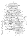
- Number 1 in the accompanying drawing indicates a number of double cigarette portions, which are fed in a direction D, crosswise to their respective longitudinal axes, along a path P defined by a succession of known suction conveyor rollers (not shown) of a filter-assembly machine (not shown).
- Path P lies in a plane G defined by the surface of the rollers (not shown) and coincident with the plane of the accompanying schematic drawing.
- Each portion 1 is substantially cylindrical, and has two opposite ends 2a, 2b formed by two successive cuts at a cutting station (not shown) of a cigarette manufacturing machine (not shown).
- a supply station 3 a cutting station 4 comprising a cutter 5; a tip turning station 6; a pairing station 7; a station 8 for inserting double filters 9 and respective projecting gummed bands 10; a rolling station 11 comprising a rolling bed R; an axial-transfer station 12; a cutting station 13 comprising a cutter 14; and a tip turning station 15.
- portions 1 are transferred to supply station 3 by a transfer device (not shown) connecting the manufacturing machine (not shown) to the filter-assembly machine (not shown). Portions 1 are fed by said transfer device (not shown) successively and in equally spaced manner in direction D to the input of the filter-assembly machine (not shown), and are fed in an orderly succession A, still in direction D and by said conveyor rollers (not shown), through cutting station 4 where cutter 5 cuts each double portion 1 into two single cigarette portions 16.
- Portions 1a and 1b are arranged alternately in succession A, and are fed through cutting station 4 where cutter 5 cuts portion 1a in half to form a pair 17 of single portions 16a, 16b, and cuts portion 1b in half to form a pair 18 of single portions 16c, 16d.
- Pairs 17 and 18 are arranged in orderly fashion in succession A, and are fed through tip turning station 6 where portions 16a, 16b in pair 17 are maintained coaxial and contacting each other end to end with respective ends 2a, 2b facing outwards, while portions 16c, 16d in pair 18 are turned over through 180° in opposite directions F1, F2, and positioned, in plane G, coaxial with each other, separated by a distance L1 substantially equal to the length of a double portion 1, and with respective ends 2a, 2b facing each other.
- Pairs 17 and 18 of portions 16a, 16b, 16c, 16d are fed in the above configuration to pairing station 7 where portions 16c, 16b are kept in the same position with respect to each other and the conveyor roller (not shown), while portion 16a is moved, in plane G, in the opposite direction to direction D into a position coaxial with portion 16c, and also in a direction perpendicular to direction D into a position separated by a given distance L from portion 16c.
- the displacement in said two directions is indicated in the accompanying drawing by arrow F3.
- portion 16d is moved, in plane G, in the same direction as direction D into a position coaxial with portion 16b, and also in a direction perpendicular to direction D into a position separated by distance L from portion 16b.
- the displacement in said two directions is indicated by arrow F4; portions 16a, 16d indicated by the dash lines are those prior to displacements F3, F4; and portions 16a, 16d indicated by the continuous lines are those after displacements F3, F4.
- portions 16a, 16b, 16c, 16d form a pair 19 of coaxial portions 16c, 16a separated by distance L, and a pair 20 of coaxial portions 16b, 16d separated by distance L; and pairs 19 and 20 are fed in direction D in two successions B and C with the same spacing P1, and partially engage one another, combfashion, by a length smaller than the length of a single portion 16. That is, portion 16b of one pair 20 is partially inserted between two portions 16a of two consecutive pairs 19 in direction D, and portion 16a of one pair 19 is partially inserted between two portions 16b of two consecutive pairs 20 in direction D. Moreover, each pair 19 is offset with respect to each adjacent pair 20 by a spacing P2 equal to half spacing P1.
- the two successions B, C of respective pairs 19, 20 are fed through station 8 where double filters 9 and respective projecting bands 10 are fed onto plane G and inserted between portions 16c and 16a of pairs 19, and between portions 16b and 16d of pairs 20 to form groups 21 arranged in successions B and C.
- station 8 the position of portions 16a, 16b, 16c, 16d remains unchanged, so that groups 21 in successions B and C are also engaged combfashion in the same way as pairs 19 and 20, and the bands 10 projecting with respect to respective filters 9, i.e. the bands 10 laid out flat, do not interfere with groups 21 in the adjacent succession B, C.
- spacing P1 is greater than the length of band 10 laid out flat in direction D, to prevent the band from interfering with the next group 21 in the same succession B, C.
- Groups 21, arranged as described, are fed inside station 11 by rolling groups 21 about their respective axes along common rolling bed R to wind bands 10 about respective double filters 9 and about ends 2a of portions 16c, 16a and ends 2b of portions 16b, 16d to form double filter-tipped cigarettes 22.
- Common rolling bed R is of a width, measured crosswise to direction D, equal to less than twice the length of a group 21, and, in a preferred embodiment, is of a width, measured crosswise to direction D, approximately equal to but no less than twice the width of band 10 plus twice the length of one portion 16a, 16b, 16c, 16d.
- one double cigarette 22 at station 12 is indicated by a continuous line in succession B and by a dash line in succession C.
- Double cigarettes 22 in single succession C are fed through cutting station 13 where cutter 14 cuts double filter 9 of each double cigarette 22 in half to form a pair of single filter-tipped cigarettes 23, each comprising a single cigarette portion 16a, 16b, 16c, 16d attached to a single filter 24 formed by cutting respective double filter 9 in half.
- the cigarettes 23 in each pair are positioned with respective filters 24 facing and adjacent to each other.
- one cigarette 23 in each pair is turned over through 180°, in the direction of arrow F6, into a position parallel to and side by side with the other cigarette 23 in the same pair, so as form a single succession of equioriented cigarettes 23, i.e. with respective filters 24 all facing the same way.
Landscapes
- Manufacturing Of Cigar And Cigarette Tobacco (AREA)
- Control Of Cutting Processes (AREA)
Claims (5)
- Un procédé de roulement de portions de cigarette, le procédé comprenant les étapes d'avancement d'une première succession (B) de premières paires (19) de portions de cigarette (16c, 16a) dans une direction (D) perpendiculaire aux axes respectifs des portions de cigarettes (16c, 16a), chaque première paire (19) comprenant une première et une deuxième portion de cigarette (16c, 16a) coaxiales à et à une distance (L) donnée de chaque autre; l'avancement d'une deuxième succession (C) de deuxièmes paires (20) de portions de cigarette (16b, 16d) dans une direction (D) transversale par rapport aux axes respectifs des portions de cigarette (16b, 16d), ladite deuxième succession (C) étant parallèle à la première succession (B), chaque deuxième paire (20) comprenant une troisième et une quatrième portions de cigarette (16b, 16d) coaxiales à et à ladite distance (L) donnée de chaque autre, et la deuxième portion de cigarette (16a) dans la première succession (B) étant adjacente à la troisième portion de cigarette (16b) se trouvant dans la deuxième succession (C) ; fourniture d'un double filtre (9) et d'une bande (10) respective, mise en saillie par rapport audit double filtre (9) entre la première et la deuxième portions de cigarette (16c, 16a) et entre la troisième et la quatrième portions de cigarette (16b, 16d) pour former des groupes (21) respectifs, chacun comprenant une paire (19; 20) de portions de cigarette (16c, 16a, 16b, 16d), un double filtre (9) et une bande (10); et roulement desdits groupes (21), agencés dans ladite première et ladite deuxième successions (B, C) pour enroulement lesdites bandes (10) autour des filtres doubles (9) respectifs et autour des extrémités de portions de cigarette (16c, 16a; 16b, 16d) respectifs pour former des cigarettes à bout filtre (22) double; le procédé étant caractérisé par le fait de comprendre l'étape de mise en prise partielle, à la façon d'un peigne, desdites premières paires (19) se trouvant dans la première succession (B) et desdites deuxièmes paires (20) se trouvant dans la deuxième succession (C) en une position relative à laquelle chaque troisième portion de cigarette (16b) est placée entre deux deuxièmes portions de cigarette (16a) adjacentes avant que lesdits groupes (21) soient roulés ;
lesdites premières et deuxièmes paires (19, 20) étant mises en prise à la façon d'un peigne d'une longueur inférieure à la longueur d'une dite portion de cigarette (16a, 16b; 16c, 16d). - Un procédé selon la revendication 1, caractérisé en ce que les groupes (21) se trouvant dans lesdites premières et deuxièmes successions (B, C) sont roulées sur un banc de roulage (R) commun.
- Un procédé selon la revendication 2, caractérisé en ce que ledit banc de roulage (R) commun est d'une largeur, mesurée transversalement à ladite direction (D), égale à moins du double de la longueur dudit groupe (21).
- Un procédé selon la revendication 2 ou 3, caractérisé en ce que ledit banc de roulage commun (R) est d'une largeur, mesurée transversalement par rapport à ladite direction (D), à peu près égale mais non inférieure au double de la largeur de ladite bande (10) plus deux fois la longueur de ladite portion de cigarette (16a, 16b; 16c, 16d).
- Un procédé selon l'une quelconque des revendications précédentes, caractérisé en ce que des portions de cigarette (16a, 16b; 16c, 16d) respectives, dans la même succession (B, C) sont espacées également d'un espacement (P1) au moins égal à la longueur de ladite bande (10).
Applications Claiming Priority (2)
| Application Number | Priority Date | Filing Date | Title |
|---|---|---|---|
| IT97BO000498A IT1293301B1 (it) | 1997-08-06 | 1997-08-06 | Metodo di rullatura di spezzoni di sigaretta. |
| ITBO970498 | 1997-08-06 |
Publications (2)
| Publication Number | Publication Date |
|---|---|
| EP0895725A1 EP0895725A1 (fr) | 1999-02-10 |
| EP0895725B1 true EP0895725B1 (fr) | 2002-12-04 |
Family
ID=11342472
Family Applications (1)
| Application Number | Title | Priority Date | Filing Date |
|---|---|---|---|
| EP98114741A Expired - Lifetime EP0895725B1 (fr) | 1997-08-06 | 1998-08-05 | Procédé de roulement de portions de cigarette |
Country Status (5)
| Country | Link |
|---|---|
| US (1) | US6131582A (fr) |
| EP (1) | EP0895725B1 (fr) |
| CN (1) | CN1220851A (fr) |
| DE (1) | DE69809850T2 (fr) |
| IT (1) | IT1293301B1 (fr) |
Cited By (1)
| Publication number | Priority date | Publication date | Assignee | Title |
|---|---|---|---|---|
| WO2022172134A1 (fr) | 2021-02-10 | 2022-08-18 | International Tobacco Machinery Poland Sp. Z O.O. | Procédé de fabrication d'articles en forme de tige pour l'industrie du tabac, appareil de fabrication d'articles en forme de tige et système de fabrication d'articles en forme de tige |
Families Citing this family (6)
| Publication number | Priority date | Publication date | Assignee | Title |
|---|---|---|---|---|
| US7170062B2 (en) * | 2002-03-29 | 2007-01-30 | Oy Ajat Ltd. | Conductive adhesive bonded semiconductor substrates for radiation imaging devices |
| DE50301741D1 (de) * | 2003-05-07 | 2005-12-29 | Hauni Maschinenbau Ag | Filteransetzmaschine mit doppelter Belagpapierzufuhr |
| DE102005012810A1 (de) * | 2005-03-17 | 2006-10-05 | Hauni Maschinenbau Ag | Verfahren zur Herstellung von Filterzigaretten |
| US20060281614A1 (en) * | 2005-06-09 | 2006-12-14 | Philip Morris Usa Inc. | Filter tube making |
| US7481757B2 (en) * | 2006-12-28 | 2009-01-27 | Philip Morris Usa Inc. | Tube rolling device |
| ITBO20110331A1 (it) * | 2011-06-08 | 2012-12-09 | Gd Spa | Metodo e macchina mettifiltro per realizzare sigarette con filtro. |
Family Cites Families (3)
| Publication number | Priority date | Publication date | Assignee | Title |
|---|---|---|---|---|
| DE1096272B (de) * | 1958-06-28 | 1960-12-29 | Hauni Werke Koerber & Co Kg | Verfahren zum Herstellen von Filtermundstueckzigaretten |
| US3080871A (en) * | 1959-04-13 | 1963-03-12 | Molins Machine Co Ltd | Manufacture of composite cigarettes |
| US4841993A (en) * | 1987-03-03 | 1989-06-27 | Korber Ag | Method of and machine for making filter cigarettes |
-
1997
- 1997-08-06 IT IT97BO000498A patent/IT1293301B1/it active IP Right Grant
-
1998
- 1998-08-05 DE DE69809850T patent/DE69809850T2/de not_active Expired - Fee Related
- 1998-08-05 EP EP98114741A patent/EP0895725B1/fr not_active Expired - Lifetime
- 1998-08-05 US US09/129,569 patent/US6131582A/en not_active Expired - Fee Related
- 1998-08-06 CN CN98116207.XA patent/CN1220851A/zh active Pending
Cited By (1)
| Publication number | Priority date | Publication date | Assignee | Title |
|---|---|---|---|---|
| WO2022172134A1 (fr) | 2021-02-10 | 2022-08-18 | International Tobacco Machinery Poland Sp. Z O.O. | Procédé de fabrication d'articles en forme de tige pour l'industrie du tabac, appareil de fabrication d'articles en forme de tige et système de fabrication d'articles en forme de tige |
Also Published As
| Publication number | Publication date |
|---|---|
| ITBO970498A0 (it) | 1997-08-06 |
| DE69809850D1 (de) | 2003-01-16 |
| DE69809850T2 (de) | 2003-10-09 |
| EP0895725A1 (fr) | 1999-02-10 |
| ITBO970498A1 (it) | 1999-02-06 |
| CN1220851A (zh) | 1999-06-30 |
| US6131582A (en) | 2000-10-17 |
| IT1293301B1 (it) | 1999-02-16 |
Similar Documents
| Publication | Publication Date | Title |
|---|---|---|
| EP0580150B1 (fr) | Procédé de fabrication de cigarettes à filtre | |
| US7296579B2 (en) | Method and device for producing filter cigarettes | |
| US6131583A (en) | Method of conveying bar-shaped articles | |
| RU2695408C1 (ru) | Устройство изготовления многоэлементных стержней в табачной промышленности | |
| EP0895725B1 (fr) | Procédé de roulement de portions de cigarette | |
| JP2854002B2 (ja) | フイルタシガレツトを造るための方法および機械 | |
| US20030234023A1 (en) | Filter feed on a filter tipping machine | |
| US5715838A (en) | Cigarette manufacture | |
| EP1519657B1 (fr) | Procede de production de cigarettes a bout filtre | |
| US6105750A (en) | Method and device for transferring articles | |
| US5033482A (en) | Method of manufacturing filter-tipped cigarettes | |
| US4040430A (en) | Method and apparatus for making filter cigarettes | |
| US4023577A (en) | Manufacture of cigarettes | |
| US3267820A (en) | Manufacture of mouthpiece for cigarettes | |
| US4848371A (en) | Filter assembly machine | |
| US5474091A (en) | Method of producing filter-tipped cigarettes | |
| DE1069518B (fr) | ||
| JP2006254911A (ja) | フィルターシガレットを製造するための方法 | |
| EP0546471B1 (fr) | Procédé de fabrication de cigarettes à filtre de différents longueurs | |
| US5076290A (en) | Filter-tipped cigarette manufacturing method | |
| KR20230039681A (ko) | 다중 세그먼트 로드형 물품 제조용 디바이스 | |
| BR102018075678A2 (pt) | Aparelho para fabricação de hastes multielemento da indústria de tabaco | |
| DE1960633A1 (de) | Verfahren und Vorrichtung zum AEndern der Teilung von in mindestens einer Reihe gefoerderten Zigaretten oder anderen stabfoermigen Tabakartikeln | |
| EP1579775A1 (fr) | Machine de fabrication de cigarettes | |
| GB1531424A (en) | Method and apparatus for making mouthpiece cigarettes |
Legal Events
| Date | Code | Title | Description |
|---|---|---|---|
| PUAI | Public reference made under article 153(3) epc to a published international application that has entered the european phase |
Free format text: ORIGINAL CODE: 0009012 |
|
| AK | Designated contracting states |
Kind code of ref document: A1 Designated state(s): DE FR GB IT |
|
| AX | Request for extension of the european patent |
Free format text: AL;LT;LV;MK;RO;SI |
|
| 17P | Request for examination filed |
Effective date: 19990719 |
|
| AKX | Designation fees paid |
Free format text: DE FR GB IT |
|
| GRAG | Despatch of communication of intention to grant |
Free format text: ORIGINAL CODE: EPIDOS AGRA |
|
| 17Q | First examination report despatched |
Effective date: 20020220 |
|
| GRAG | Despatch of communication of intention to grant |
Free format text: ORIGINAL CODE: EPIDOS AGRA |
|
| GRAH | Despatch of communication of intention to grant a patent |
Free format text: ORIGINAL CODE: EPIDOS IGRA |
|
| GRAH | Despatch of communication of intention to grant a patent |
Free format text: ORIGINAL CODE: EPIDOS IGRA |
|
| GRAA | (expected) grant |
Free format text: ORIGINAL CODE: 0009210 |
|
| RAP1 | Party data changed (applicant data changed or rights of an application transferred) |
Owner name: G.D SOCIETA' PER AZIONI |
|
| AK | Designated contracting states |
Kind code of ref document: B1 Designated state(s): DE FR GB IT |
|
| REG | Reference to a national code |
Ref country code: GB Ref legal event code: FG4D |
|
| REF | Corresponds to: |
Ref document number: 69809850 Country of ref document: DE Date of ref document: 20030116 |
|
| ET | Fr: translation filed | ||
| PLBQ | Unpublished change to opponent data |
Free format text: ORIGINAL CODE: EPIDOS OPPO |
|
| PLBI | Opposition filed |
Free format text: ORIGINAL CODE: 0009260 |
|
| 26 | Opposition filed |
Opponent name: HAUNI MASCHINENBAU AG Effective date: 20030812 |
|
| PLAX | Notice of opposition and request to file observation + time limit sent |
Free format text: ORIGINAL CODE: EPIDOSNOBS2 |
|
| PLAX | Notice of opposition and request to file observation + time limit sent |
Free format text: ORIGINAL CODE: EPIDOSNOBS2 |
|
| PLBB | Reply of patent proprietor to notice(s) of opposition received |
Free format text: ORIGINAL CODE: EPIDOSNOBS3 |
|
| PLCK | Communication despatched that opposition was rejected |
Free format text: ORIGINAL CODE: EPIDOSNREJ1 |
|
| PLBN | Opposition rejected |
Free format text: ORIGINAL CODE: 0009273 |
|
| STAA | Information on the status of an ep patent application or granted ep patent |
Free format text: STATUS: OPPOSITION REJECTED |
|
| 27O | Opposition rejected |
Effective date: 20060327 |
|
| PGFP | Annual fee paid to national office [announced via postgrant information from national office to epo] |
Ref country code: GB Payment date: 20060825 Year of fee payment: 9 |
|
| PGFP | Annual fee paid to national office [announced via postgrant information from national office to epo] |
Ref country code: IT Payment date: 20060831 Year of fee payment: 9 Ref country code: FR Payment date: 20060831 Year of fee payment: 9 |
|
| PGFP | Annual fee paid to national office [announced via postgrant information from national office to epo] |
Ref country code: DE Payment date: 20061002 Year of fee payment: 9 |
|
| GBPC | Gb: european patent ceased through non-payment of renewal fee |
Effective date: 20070805 |
|
| REG | Reference to a national code |
Ref country code: FR Ref legal event code: ST Effective date: 20080430 |
|
| PG25 | Lapsed in a contracting state [announced via postgrant information from national office to epo] |
Ref country code: DE Free format text: LAPSE BECAUSE OF NON-PAYMENT OF DUE FEES Effective date: 20080301 |
|
| PG25 | Lapsed in a contracting state [announced via postgrant information from national office to epo] |
Ref country code: FR Free format text: LAPSE BECAUSE OF NON-PAYMENT OF DUE FEES Effective date: 20070831 |
|
| PG25 | Lapsed in a contracting state [announced via postgrant information from national office to epo] |
Ref country code: GB Free format text: LAPSE BECAUSE OF NON-PAYMENT OF DUE FEES Effective date: 20070805 |
|
| PG25 | Lapsed in a contracting state [announced via postgrant information from national office to epo] |
Ref country code: IT Free format text: LAPSE BECAUSE OF NON-PAYMENT OF DUE FEES Effective date: 20070805 |