EP0895924B1 - Chenille de caoutchouc - Google Patents
Chenille de caoutchouc Download PDFInfo
- Publication number
- EP0895924B1 EP0895924B1 EP98306306A EP98306306A EP0895924B1 EP 0895924 B1 EP0895924 B1 EP 0895924B1 EP 98306306 A EP98306306 A EP 98306306A EP 98306306 A EP98306306 A EP 98306306A EP 0895924 B1 EP0895924 B1 EP 0895924B1
- Authority
- EP
- European Patent Office
- Prior art keywords
- rubber
- crawler
- metal core
- elastomer
- rubber crawler
- Prior art date
- Legal status (The legal status is an assumption and is not a legal conclusion. Google has not performed a legal analysis and makes no representation as to the accuracy of the status listed.)
- Expired - Lifetime
Links
- 229920001971 elastomer Polymers 0.000 title claims description 183
- 239000005060 rubber Substances 0.000 title claims description 133
- 239000002184 metal Substances 0.000 claims description 69
- 239000000806 elastomer Substances 0.000 claims description 50
- 230000002093 peripheral effect Effects 0.000 claims description 21
- 229910000831 Steel Inorganic materials 0.000 claims description 19
- 239000010959 steel Substances 0.000 claims description 19
- 238000005336 cracking Methods 0.000 description 4
- 238000005452 bending Methods 0.000 description 3
- 230000015572 biosynthetic process Effects 0.000 description 2
- 230000000694 effects Effects 0.000 description 2
- 238000010008 shearing Methods 0.000 description 2
- 239000004575 stone Substances 0.000 description 2
- 239000012141 concentrate Substances 0.000 description 1
- 230000000116 mitigating effect Effects 0.000 description 1
- 230000008719 thickening Effects 0.000 description 1
Images





Classifications
-
- B—PERFORMING OPERATIONS; TRANSPORTING
- B62—LAND VEHICLES FOR TRAVELLING OTHERWISE THAN ON RAILS
- B62D—MOTOR VEHICLES; TRAILERS
- B62D55/00—Endless track vehicles
- B62D55/08—Endless track units; Parts thereof
- B62D55/18—Tracks
- B62D55/26—Ground engaging parts or elements
Definitions
- This invention relates to a rubber crawler, and more particularly to a rubber crawler having a structure for preventing the occurrence of cracking or breakage in each of widthwise edge portions of rubber in the crawler.
- This rubber crawler shown in Fig. 1 comprises an endless rubber belt 1, a plurality of core metal pieces 2 arranged and buried at predetermined intervals in the longitudinal direction of the belt 1, and steel cords 3 arranged so as to cover the outer surface of the metal pieces 2 and buried in the longitudinal direction of the belt 1. Since a widthwise length of the metal piece 2 is shorter than the full width of the belt 1, widthwise edge portions 4 made from only rubber are formed at both sides of the belt 1.
- the widthwise edge portion of the core metal piece has a vertically cut shape at its widthwise edge and front and back edges and has high flexibility as a whole of the rubber crawler, so that deformation strain is liable to be most caused in the widthwise edge portion at a use state of the rubber crawler.
- the rubber crawler contacts with or rides on protrusions such as pebbles, stone pieces, and the like scattered on a running road or a kerb 10 of a footpath as shown in Fig.
- the widthwise edge portion 4 is sandwiched between the core metal piece 2 and the kerb 10 and shearing force strongly and repeatedly acts to the widthwise edge of the core metal piece during the running of the rubber crawler to thereby create a crack C from the vicinity of such an edge toward an outer surface of the widthwise edge portion 4.
- Such a crack grows toward the side of contacting with the ground and further toward the front and back sides of the widthwise edge portion due to repetition of deformation stress to finally cause breakage of the widthwise edge portion.
- the durability of rubber constituting the widthwise edge portion and hence the service life of the rubber crawler are undesirably degraded.
- EP-0493875A which describes, with reference to Figs. 1, 2 and 3 thereof, a rubber crawler (4) according to the preamble of independent claims 1 and 2 comprising a rubbery elastomer (5) constituting a main body of the crawler, at least one metal core (6) buried in the rubbery elastomer (5) and extending in a widthwise direction perpendicular to a running direction of the crawler (4), and at least one ground engaging rubber lug (8) formed on an outer peripheral face of the rubber elastomer.
- an object of the present invention to solve the aforementioned problem of the conventional rubber crawler and to provide a rubber crawler capable of reducing or preventing the occurrence of cracks or breakage in the widthwise edge portions of rubber due to contacting with or riding on protrusions scattered on a road or a kerb of a footpath.
- a rubber crawler comprising a rubbery elastomer constituting a main body of the crawler, at least one metal core buried in the rubbery elastomer and extending in a widthwise direction perpendicular to a running direction of the crawler, and at least one ground engaging rubber lug formed on an outer peripheral face of the rubber elastomer, characterized in that a rib having a round shape in section is formed at each widthwise end of the metal core.
- a rubber crawler comprising a rubbery elastomer constituting a main body of the crawler, at least one metal core buried in the rubbery elastomer and extending in a widthwise direction perpendicular to a running direction of the crawler, and at least one ground engaging rubber lug formed on an outer peripheral face of the rubber elastomer, characterized in that a bent portion directing toward an inner peripheral side of the crawler so as to separate away from a ground contact face of the rubber lug is formed at each widthwise end of the metal core, said inner peripheral side of the crawler being on the opposite side of said main body to said outer peripheral face.
- an inclination angle ⁇ of the bent portion with respect to an outer horizontal peripheral face of the metal core is 15-45° more preferably 20-35°.
- the inclination angle ⁇ is less than 15°, the effect of preventing the bending deformation of the widthwise side portion is less, while it exceeds 45°, interference to a driving wheel in the crawler is liable to be undesirably caused.
- the bent portion is provided with an outside-to-inside path, communicating an outer surface of said bent portion to an inner surface thereof.
- the rubber elastomer when the rubber elastomer is an endless rubber belt, a row of plural steel cords arranged side by side is buried in the rubber elastomer along an outer surface of the metal core so as to extend said steel cords in the circumferential direction of the rubber elastomer and each of outermost steel cords in the steel cord row is located inward from the widthwise end of the metal core by not less than 15 mm.
- an edge of a plane surface in a widthwise end portion of the rubber elastomer facing to ground is located outward from an outer surface of the metal core.
- a first embodiment of the metal core 12 used in the rubber crawler according to the invention is shown as a plan view in Fig. 3, as a bottom view in Fig. 4, as a front view in Fig. 5 and as a right side view in Fig. 6, respectively.
- numeral 14 is a portion engaging with a sprocket (not shown) and wing portions 15, 16 are formed on both sides of the sprocket engaging portion 14 and also a pair of projections 17, 18 sandwiching the sprocket engaging portion 14 are arranged in zigzag formation.
- ribs 19, 20 having a round shape in section are formed at longitudinal ends of the wing portions 17, 18, respectively.
- the ribs 19, 20 are formed at the side directed toward the inner peripheral side of the rubber crawler.
- numerals 21, 22 are ribs formed on the wing portions 15, 16 from the vicinity of the longitudinal end thereof toward the projections 17, 18, respectively.
- the metal core 12 has a longitudinal length of 290 mm and a width of 30 mm
- the sprocket engaging portion 14 has a distance between the projections 17, 18 of 46 mm and a height from the bottom of 27 mm
- the length of each of the wing portions 15, 16 is 122 mm.
- the thickness in the vicinity of the longitudinal end of the wing portion 15, 16 is about 37 mm
- each of the ribs 19, 20 has a radius of 6 mm.
- each of the projections 17, 18 has a width at its top of 15 mm and a height from the bottom of 50 mm.
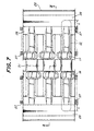
- a first embodiment of the rubber crawler 24 according to the invention using the metal core 12 shown in Figs. 3-6 is shown as a plan view in Fig. 7, as a bottom view in Fig. 8, as a right side view in Fig. 9 and as a section view in Fig. 10, respectively.
- numeral 26 is an endless rubber elastomer containing a plurality of the metal cores 12 at a given pitch in the longitudinal direction thereof.
- a row of steel cords 27 arranged side by side are buried in the rubber elastomer 26 along a bottom surface of the wing portions 15, 16 of the metal core 12 in the longitudinal direction of the rubber elastomer 26. Therefore, widthwise end portions 28, 29 made of only rubber are formed outward from both ends of the metal core 12 in the rubber elastomer 26.
- numeral 30 is a rubber lug formed on the outer peripheral surface of the rubber elastomer 26 at the side of contacting with the ground and numeral 31 is a sprocket hole defined between the sprocket engaging portions of the adjacent metal cores 12 in which sprocket teeth (not shown) of a driving wheel (not shown) engage.
- rubber constituting the widthwise end portions 28, 29 is adhered to the ribs 19, 20 formed in the longitudinal ends of the metal core 12, so that the adhesion area is widened to increase the adhesion strength. Further, when the rubber crawler 24 contacts with or rides on a kerb of a footpath or the like, shearing force does not concentrate in rubber of the widthwise end portion 28, 29 owing to the presence of the ribs 19, 20 and hence the occurrence of cracking in the widthwise end portion 28, 29 is reduced to prevent the breakage of the widthwise end portion 28, 29.
- each of outermost steel cords 27 in the steel cord row is located inward from the longitudinal end of the wing portions 15, 16 of the metal core 12 by a given distance L of not less than 15 mm. Even if a crack is caused in the vicinity of the rib 19, 20, it does not arrive at the outermost steel cord 27 in the steel cord row and hence the growth of the crack in the longitudinal direction of the rubber crawler is not caused.
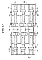
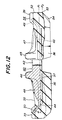
- a second embodiment of the rubber crawler 34 according to the invention is shown as a plan view in Fig. 11 and as a section view in Fig. 12.
- a second embodiment of the metal core 40 used in the rubber crawler 34 comprises a sprocket engaging portion 42, a pair of wing portions 43, 44 formed on both sides thereof, a pair of projections 45, 46 sandwiching the sprocket engaging portion 42, ribs 47, 48 formed on the wing portions 43, 44 toward the projections 45, 46 and bent portions 49, 50 formed by bending longitudinal ends of the wing portions 43, 44 toward an inner peripheral side of the rubber crawler 34.
- numeral 35 is an endless rubber elastomer containing a plurality of the metal cores 40 at a given pitch in the longitudinal direction thereof
- numeral 36 is a rubber lug rubber lug formed on the outer peripheral surface of the rubber elastomer 35 at the side contacting with the ground
- numeral 37 is steel cords arranged side by side in a row and buried in the rubber elastomer 35 along a bottom surface of the wing portions 43, 44 of the metal core 40 in the longitudinal direction of the rubber elastomer 35
- numeral 38 is a sprocket hole defined between the sprocket engaging portions of the adjacent metal cores 40 in which sprocket teeth (not shown) of a driving wheel (not shown) engage.
- a thickening portion 39 is formed in a widthwise and inner end portion of the rubber elastomer 35 so as to cover the bent portion 49, 50.
- an edge 53 of a flat end face 52 of the rubber elastomer 35 in the widthwise direction thereof is located (P 2 ) outward from a horizontal position P 1 of an outer peripheral face of the metal core 40, whereby the rubber thickness in the widthwise end portion of the rubber elastomer is increased to separate away a position of crack concentration from the widthwise end of the metal core 40 in the widthwise end portion of the rubber elastomer 35.
- numeral 54 is a slant face at the widthwise end of the rubber lug 36.
- the inclination angle ⁇ of the bent portion 50 with respect to the outer horizontal face of the metal core 40 is about 30°.
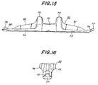
- a third embodiment of the metal core 70 used in the rubber crawler according to the invention is shown as a plan view in Fig. 13, as a bottom view in Fig. 14, as a front view in Fig. 15 and as a right side view in Fig. 16, respectively.
- numeral 72 is a portion engaging with a sprocket (not shown) and wing portions 73, 74 are formed on both sides of the sprocket engaging portion 72 and also a pair of projections 75, 76 sandwiching the sprocket engaging portion 72 are arranged in zigzag formation.
- bent portions 77, 78 are formed at longitudinal ends of the wing portions 73, 74, respectively.
- the bent portions 77, 78 are formed at the side directed toward one inner peripheral side of the rubber crawler so as to have an inclination angle ⁇ of 20-40° with respect to an outer horizontal face of the metal core 70.
- each of the bent portions 77, 78 is provided with an outside-to-inside path 79, 80 communicating an outer surface of the bent portion 77, 78 with an inner surface thereof, in which the path 79 is a notch portion formed in both sides of the bent portion 77 and the path 80 is a through-hole formed in the bent portion 78.
- numerals 81, 82 are ribs formed on the wing portions 73, 74 from the vicinity of the longitudinal end thereof toward the projections 75, 76, respectively.
- the bent portion 77, 78 has a length of about 10-25 mm.
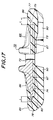
- a third embodiment of the rubber crawler 84 according to the invention using the metal core 70 shown in Figs. 13-16 is shown as a section view in Fig. 17.
- numeral 86 is an endless rubber elastomer containing a plurality of the metal cores 70 at a given pitch in the longitudinal direction thereof.
- a row of steel cords 87 arranged side by side are buried in the rubber elastomer 86 along a bottom surface of the wing portions 73, 74 of the metal core 70 in the longitudinal direction of the rubber elastomer 86. Therefore, widthwise end portions 88, 89 made of only rubber are formed outward from both ends of the metal core 70 in the rubber elastomer 86.
- numeral 90 is a rubber lug formed on the outer peripheral surface of the rubber elastomer 86 at the side contacting with the ground.
- a sprocket hole (not shown) is defined between the sprocket engaging portions 72 of the adjacent metal cores 70 in which sprocket teeth (not shown) of a driving wheel (not shown) engage.
- rubber constituting the widthwise end portions 88, 89 is adhered to the bent portions 77, 78 formed in the longitudinal ends of the metal core 70, so that the adhesion area is widened to increase the adhesion strength.
- the rubber thickness of the widthwise end portion 88, 89 located outward from the outer surface of the bent portion 77, 78 is thicker than that of the conventionally used crawler. Since the rubber thickness generally contributes to the mitigation of stress in the deformation of rubber, the rubber thickness of the widthwise end portion 88, 89 mitigates the concentration of stress even when the rubber crawler 84 contacts with or rides on a kerb of a footpath or the like and hence the occurrence of cracks is not caused.
- each of outermost steel cords 87 in the steel cord row is located inward from the longitudinal end of the wing portions 73, 74 of the metal core 70 by a given distance L, so that the same effect as in the first embodiment is obtained.
- rubbers of the rubber elastomer 86 located on the outer and inner faces of the bent portion 77, 78 are further connected to each other through the path 79, 80, so that the peeling of rubber from the bent portion is prevented.
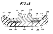
- the rubber crawler 94 is shown in Fig. 18.
- the rubber crawler 94 comprises an endless rubber elastomer 96, a plurality of metal cores 98 buried in the rubber elastomer 96 at a given pitch in the longitudinal direction, steel cords 99 arranged side by side in a row and buried in the rubber elastomer 96 along the outer horizontal face of the metal core 98 in the longitudinal direction of the rubber elastomer 96, and a rubber lug 100 formed on the outer surface of the rubber elastomer 96.
- the metal core 98 comprises a sprocket engaging portion 102, a pair of wing portions 103, 104 formed on both sides of the sprocket engaging portion 102, a pair of projections 105, 106 sandwiching the sprocket engaging portion 102, bent portions 107, 108 formed by curvedly bending longitudinal ends of the wing portions 103, 104 toward an inner peripheral side of the rubber crawler 94, and rib portions 109, 110 formed at the longitudinal ends of the bent portions 107, 108. Since the bent portion 107, 108 has a curved form, a point of starting an occurrence of strain can be more dispersed inward from the longitudinal end of the metal core to prevent the occurrence of cracks.
- a sprocket hole is defined between the sprocket engaging portions 102 of the adjacent metal cores 94 in which sprocket teeth (not shown) of a driving wheel (not shown) engage.
- the rubber thickness in widthwise end portions of the rubber lug 100 may be increased toward the side contacting with the ground as shown by a phantom line.
- a specified means is applied to a widthwise end portion of a metal core buried in a rubber elastomer to prevent the occurrence of cracking in the widthwise end portion made of only rubber and breakage of the widthwise end portion accompanied with the growth of the crack in the longitudinal direction of the rubber elastomer or a direction towards a ground contact face when the rubber crawler contacts with or rides on protrusions such as pebbles, stone pieces, and the like scattered on a running road or a kerb of a footpath, whereby the durable life of the rubber crawler can be considerably improved.
Landscapes
- Engineering & Computer Science (AREA)
- Chemical & Material Sciences (AREA)
- Combustion & Propulsion (AREA)
- Transportation (AREA)
- Mechanical Engineering (AREA)
- Laminated Bodies (AREA)
Claims (8)
- Chenille en caoutchouc (24) comprenant un élastomère caoutchouteux (26) constituant un corps principal de la chenille, au moins un noyau métallique (12) noyé dans l'élastomère caoutchouteux et s'étendant dans une direction de la largeur, perpendiculaire à une direction de roulement de la chenille, et au moins une patte en caoutchouc s'engageant dans le sol (30) formée sur une face périphérique externe de l'élastomère caoutchouteux, caractérisée en ce qu'une nervure (19, 20) ayant une section transversale de forme ronde est formée au niveau de chaque extrémité dans le sens de la largeur du noyau métallique (12).
- Chenille en caoutchouc (34; 84; 94) comprenant un élastomère caoutchouteux (35; 86; 96) constituant un corps principal de la chenille, au moins un noyau métallique (40 ; 70 ; 98) noyé dans l'élastomère caoutchouteux et s'étendant dans une direction de la largeur perpendiculaire à une direction de roulement de la chenille, et au moins une patte en caoutchouc s'engageant dans le sol (36; 90; 100) formée sur une face périphérique externe de l'élastomère caoutchouteux, caractérisé en ce qu'une partie pliée (49, 50; 77, 78; 107, 108) est dirigée vers un côté périphérique interne de la chenille (34; 84; 94) de sorte à établir une séparation par rapport à la face de contact au sol de la patte en caoutchouc (36; 90; 100) est formée au niveau de chaque extrémité dans le sens de la largeur du noyau métallique (40; 70; 98), ledit côté périphérique interne de la chenille étant situé sur le côté opposé audit corps principal par rapport à ladite face périphérique externe.
- Chenille en caoutchouc selon la revendication 2, caractérisée en ce qu'un angle d'inclinaison de la partie pliée (49, 50; 77, 78) par rapport à une face périphérique horizontale externe du noyau métallique (40; 70) est compris entre 15 et 45°.
- Chenille en caoutchouc selon la revendication 3, caractérisée en ce que ledit angle d'inclinaison est compris entre 20 et 35°.
- Chenille en caoutchouc selon l'une quelconque des revendications 2 à 4, caractérisée en ce que la partie pliée (77, 78) du noyau métallique (70) comporte une trajectoire allant de l'extérieur vers l'intérieur (79, 80) établissant une communication entre une surface externe de ladite partie pliée et une surface interne correspondante.
- Chenille en caoutchouc selon l'une quelconque des revendications 1 à 5, caractérisée en ce que, lorsque l'élastomère caoutchouteux (26; 35; 86; 96) est une courroie en caoutchouc sans fin, une rangée de plusieurs câblés en acier (27; 437; 87; 99) agencés côte à côte, est noyée dans l'élastomère caoutchouteux le long d'une surface externe du noyau métallique (12; 40; 70; 98), de sorte à étendre lesdits câblés dans la direction circonférentielle de l'élastomère caoutchouteux, chacun des câblés d'acier les plus externes dans la rangée de câblés d'acier étant agencé vers l'intérieur de l'extrémité dans le sens de la largeur du noyau métalliques (12; 40; 70; 98) d'une distance non inférieure à 15 mm.
- Chenille en caoutchouc selon l'une quelconque des revendications 2 à 4, caractérisée en ce qu'un bord (53) d'une surface plane (52) dans une partie d'extrémité dans le sens de la largeur de l'élastomère caoutchouteux (35) faisant face au sol est agencé vers l'extérieur d'une surface externe du noyau métallique (40).
- Chenille en caoutchouc (94) selon la revendication 2, caractérisée en ce que lesdites parties pliées (107, 108) ont une forme courbée, chaque partie pliée (107, 108) comportant au niveau de son extrémité une nervure (109, 110) ayant une section transversale de forme ronde.
Applications Claiming Priority (6)
| Application Number | Priority Date | Filing Date | Title |
|---|---|---|---|
| JP22587197 | 1997-08-06 | ||
| JP22587197 | 1997-08-06 | ||
| JP225871/97 | 1997-08-06 | ||
| JP296387/97 | 1997-10-14 | ||
| JP29638797 | 1997-10-14 | ||
| JP9296387A JPH11105754A (ja) | 1997-08-06 | 1997-10-14 | 耳部切断を防止した芯金及びゴムクロ−ラの構造 |
Publications (3)
| Publication Number | Publication Date |
|---|---|
| EP0895924A2 EP0895924A2 (fr) | 1999-02-10 |
| EP0895924A3 EP0895924A3 (fr) | 2000-03-29 |
| EP0895924B1 true EP0895924B1 (fr) | 2002-02-06 |
Family
ID=26526876
Family Applications (1)
| Application Number | Title | Priority Date | Filing Date |
|---|---|---|---|
| EP98306306A Expired - Lifetime EP0895924B1 (fr) | 1997-08-06 | 1998-08-06 | Chenille de caoutchouc |
Country Status (4)
| Country | Link |
|---|---|
| US (1) | US6106083A (fr) |
| EP (1) | EP0895924B1 (fr) |
| JP (1) | JPH11105754A (fr) |
| DE (1) | DE69803728T2 (fr) |
Families Citing this family (41)
| Publication number | Priority date | Publication date | Assignee | Title |
|---|---|---|---|---|
| EP1008509B1 (fr) * | 1997-09-05 | 2005-11-23 | Komatsu Ltd | Patin plat elastique |
| BE1012772A3 (nl) * | 1999-07-02 | 2001-03-06 | Tweco | Rubber ketting. |
| US6984006B2 (en) | 2000-03-03 | 2006-01-10 | Komatsu Limited | Elastic flat tread |
| JP4481434B2 (ja) * | 2000-05-17 | 2010-06-16 | 株式会社ブリヂストン | ゴムクローラ |
| JP3805974B2 (ja) * | 2000-12-01 | 2006-08-09 | 住友ゴム工業株式会社 | 弾性クローラ |
| JP4408624B2 (ja) * | 2000-12-07 | 2010-02-03 | 株式会社ブリヂストン | ゴムクローラ |
| JP4646456B2 (ja) * | 2001-07-23 | 2011-03-09 | 株式会社小松製作所 | 履板 |
| US7121636B2 (en) | 2001-09-04 | 2006-10-17 | Ingersoll-Rand Company | Endless track for paving vehicles |
| JP4087619B2 (ja) * | 2002-02-27 | 2008-05-21 | 住友ゴム工業株式会社 | 弾性クローラ |
| JP2003335275A (ja) | 2002-05-22 | 2003-11-25 | Fukuyama Rubber Ind Co Ltd | ゴムクローラ |
| CN100465047C (zh) * | 2003-12-04 | 2009-03-04 | 杰尼士产业株式会社 | 弹性履带 |
| WO2005073060A1 (fr) * | 2004-01-29 | 2005-08-11 | Bridgestone Corporation | Engin mobile a chenilles en caoutchouc sans noyau |
| JP4522104B2 (ja) * | 2004-02-02 | 2010-08-11 | 福山ゴム工業株式会社 | ゴムクローラ用芯金 |
| US8465109B2 (en) | 2005-03-30 | 2013-06-18 | Fukuyama Gomu Kogyo Kabushiki Gaisha | Core bar for rubber crawler |
| USD574021S1 (en) * | 2005-10-28 | 2008-07-29 | Wirtgen Gmbh | Crawler track link assembly |
| USD549741S1 (en) * | 2006-01-31 | 2007-08-28 | Bridgestone Corporation | Rubber crawler |
| JP5199086B2 (ja) | 2006-06-22 | 2013-05-15 | 株式会社ブリヂストン | ゴムクローラの構造 |
| USD562353S1 (en) * | 2006-07-24 | 2008-02-19 | Bridgestone Corporation | Rubber crawler |
| USD557713S1 (en) * | 2006-07-24 | 2007-12-18 | Bridgestone Corporation | Rubber crawler |
| USD561786S1 (en) | 2006-09-08 | 2008-02-12 | Bridgestone Corporation | Rubber crawler |
| US20100033010A1 (en) * | 2007-03-06 | 2010-02-11 | Bridgestone Corporation | Rubber track |
| USD567823S1 (en) * | 2007-06-04 | 2008-04-29 | Bridgestone Corporation | Rubber crawler |
| USD565605S1 (en) * | 2007-08-09 | 2008-04-01 | Bridgestone Corporation | Rubber crawler |
| JP2009292204A (ja) * | 2008-06-03 | 2009-12-17 | Bridgestone Corp | ゴムクローラ |
| USD587728S1 (en) * | 2008-06-10 | 2009-03-03 | Bridgestone Corporation | Metallic core of rubber crawler |
| USD588167S1 (en) * | 2008-06-10 | 2009-03-10 | Bridgestone Corporation | Metallic core of rubber crawler |
| USD588168S1 (en) * | 2008-06-10 | 2009-03-10 | Bridgestone Corporation | Metallic core of rubber crawler |
| USD618254S1 (en) * | 2009-03-31 | 2010-06-22 | Bridgestone Corporation | Rubber crawler |
| USD615106S1 (en) * | 2009-03-31 | 2010-05-04 | Bridgestone Corporation | Rubber crawler |
| US8888198B2 (en) * | 2009-04-22 | 2014-11-18 | Bridgestone Corporation | Rubber crawler |
| USD618710S1 (en) * | 2009-05-26 | 2010-06-29 | Bridgestone Corporation | Rubber crawler |
| USD617816S1 (en) * | 2009-05-26 | 2010-06-15 | Bridgestone Corporation | Metallic core of rubber crawler |
| USD615105S1 (en) * | 2009-05-26 | 2010-05-04 | Bridgestone Corporation | Rubber crawler |
| USD618255S1 (en) * | 2009-05-26 | 2010-06-22 | Bridgestone Corporation | Metallic core of rubber crawler |
| JP5411627B2 (ja) * | 2009-08-27 | 2014-02-12 | 株式会社ブリヂストン | ゴムクローラ |
| USD655724S1 (en) * | 2011-04-14 | 2012-03-13 | Bridgestone Corporation | Metallic core of rubber crawler |
| USD676068S1 (en) * | 2011-10-25 | 2013-02-12 | Bridgestone Corporation | Metallic core of rubber crawler |
| USD761328S1 (en) * | 2015-05-21 | 2016-07-12 | Xenith Track Co., Ltd. | Metallic core of rubber crawler |
| USD761331S1 (en) * | 2015-05-21 | 2016-07-12 | Xenith Track Co., Ltd. | Metallic core of rubber crawler |
| USD761329S1 (en) * | 2015-05-21 | 2016-07-12 | Xenith Track Co., Ltd. | Metallic core of rubber crawler |
| USD761330S1 (en) * | 2015-05-21 | 2016-07-12 | Xenith Track Co., Ltd. | Metallic core of rubber crawler |
Family Cites Families (9)
| Publication number | Priority date | Publication date | Assignee | Title |
|---|---|---|---|---|
| JPS5519683A (en) * | 1978-07-29 | 1980-02-12 | Iseki & Co Ltd | Core for endless rubber belt |
| JPS56142763A (en) * | 1980-04-08 | 1981-11-07 | Kubota Ltd | Crawler running gear for farm working vehicle |
| JPS5873483A (ja) * | 1981-10-28 | 1983-05-02 | Bridgestone Corp | 弾性無限軌道帯 |
| JPS5893679A (ja) * | 1981-11-27 | 1983-06-03 | Bridgestone Corp | 弾性無限軌道帯 |
| JPS58152682A (ja) * | 1982-03-05 | 1983-09-10 | Bridgestone Corp | 弾性無限軌道帯 |
| JPH03239682A (ja) * | 1990-02-15 | 1991-10-25 | Kubota Corp | クローラ走行装置 |
| JP2768541B2 (ja) * | 1990-06-02 | 1998-06-25 | 本田技研工業株式会社 | 雪上用クローラ |
| EP0493875B1 (fr) * | 1990-12-20 | 1995-12-20 | Bridgestone Corporation | Chenille en caoutchouc |
| EP1008509B1 (fr) * | 1997-09-05 | 2005-11-23 | Komatsu Ltd | Patin plat elastique |
-
1997
- 1997-10-14 JP JP9296387A patent/JPH11105754A/ja active Pending
-
1998
- 1998-08-05 US US09/129,225 patent/US6106083A/en not_active Expired - Lifetime
- 1998-08-06 EP EP98306306A patent/EP0895924B1/fr not_active Expired - Lifetime
- 1998-08-06 DE DE69803728T patent/DE69803728T2/de not_active Expired - Lifetime
Also Published As
| Publication number | Publication date |
|---|---|
| US6106083A (en) | 2000-08-22 |
| EP0895924A2 (fr) | 1999-02-10 |
| JPH11105754A (ja) | 1999-04-20 |
| EP0895924A3 (fr) | 2000-03-29 |
| DE69803728D1 (de) | 2002-03-21 |
| DE69803728T2 (de) | 2002-08-22 |
Similar Documents
| Publication | Publication Date | Title |
|---|---|---|
| US6106083A (en) | Rubber crawler | |
| EP0913321B1 (fr) | Chenille en caoutchouc | |
| EP1386831B1 (fr) | Chenille elastique | |
| CA2994092C (fr) | Chenille elastique et dispositif a chenille elastique | |
| US7469976B2 (en) | Rubber crawler belt having metal cores and arcuate lugs | |
| US5997110A (en) | Core metal for rubber crawler | |
| JP4146001B2 (ja) | 弾性クローラおよび弾性クローラ用幅方向補強体 | |
| US10435090B2 (en) | Elastic crawler | |
| EP2275327B1 (fr) | Chenille en caoutchouc | |
| US7063395B2 (en) | Laterally reinforced endless belt track | |
| JPH08192779A (ja) | 弾性クローラ | |
| JPH08150970A (ja) | クローラ用弾性履帯 | |
| JP2001048067A (ja) | ゴムクローラ及びこれに用いる芯金 | |
| JP4136002B2 (ja) | ゴムクロ−ラ | |
| JP4347930B2 (ja) | ゴムクロ−ラ及びこれに用いる芯金 | |
| JPS6328067Y2 (fr) | ||
| JP4481434B2 (ja) | ゴムクローラ | |
| JP2000159161A (ja) | ゴムクローラ | |
| JPH0623514Y2 (ja) | クローラ | |
| JP2004114787A (ja) | 弾性クローラ | |
| JPS6411513B2 (fr) | ||
| JPS635311B2 (fr) | ||
| JPH07108960A (ja) | ゴムクロ−ラ用芯金 | |
| JPH10138964A (ja) | 弾性履帯 | |
| JPH1120752A (ja) | ゴムクロ−ラ |
Legal Events
| Date | Code | Title | Description |
|---|---|---|---|
| PUAI | Public reference made under article 153(3) epc to a published international application that has entered the european phase |
Free format text: ORIGINAL CODE: 0009012 |
|
| AK | Designated contracting states |
Kind code of ref document: A2 Designated state(s): DE FR GB IT |
|
| AX | Request for extension of the european patent |
Free format text: AL;LT;LV;MK;RO;SI |
|
| PUAL | Search report despatched |
Free format text: ORIGINAL CODE: 0009013 |
|
| AK | Designated contracting states |
Kind code of ref document: A3 Designated state(s): AT BE CH CY DE DK ES FI FR GB GR IE IT LI LU MC NL PT SE |
|
| AX | Request for extension of the european patent |
Free format text: AL;LT;LV;MK;RO;SI |
|
| 17P | Request for examination filed |
Effective date: 20000411 |
|
| AKX | Designation fees paid |
Free format text: DE FR GB IT |
|
| 17Q | First examination report despatched |
Effective date: 20001026 |
|
| GRAG | Despatch of communication of intention to grant |
Free format text: ORIGINAL CODE: EPIDOS AGRA |
|
| GRAG | Despatch of communication of intention to grant |
Free format text: ORIGINAL CODE: EPIDOS AGRA |
|
| GRAH | Despatch of communication of intention to grant a patent |
Free format text: ORIGINAL CODE: EPIDOS IGRA |
|
| GRAH | Despatch of communication of intention to grant a patent |
Free format text: ORIGINAL CODE: EPIDOS IGRA |
|
| GRAA | (expected) grant |
Free format text: ORIGINAL CODE: 0009210 |
|
| REG | Reference to a national code |
Ref country code: GB Ref legal event code: IF02 |
|
| AK | Designated contracting states |
Kind code of ref document: B1 Designated state(s): DE FR GB IT |
|
| REF | Corresponds to: |
Ref document number: 69803728 Country of ref document: DE Date of ref document: 20020321 |
|
| ET | Fr: translation filed | ||
| PLBE | No opposition filed within time limit |
Free format text: ORIGINAL CODE: 0009261 |
|
| STAA | Information on the status of an ep patent application or granted ep patent |
Free format text: STATUS: NO OPPOSITION FILED WITHIN TIME LIMIT |
|
| 26N | No opposition filed |
Effective date: 20021107 |
|
| REG | Reference to a national code |
Ref country code: FR Ref legal event code: CA Effective date: 20140812 |
|
| REG | Reference to a national code |
Ref country code: DE Ref legal event code: R081 Ref document number: 69803728 Country of ref document: DE Owner name: BRIDGESTONE CORPORATION, JP Free format text: FORMER OWNER: BRIDGESTONE CORP., TOKIO/TOKYO, JP Effective date: 20140828 |
|
| REG | Reference to a national code |
Ref country code: FR Ref legal event code: PLFP Year of fee payment: 19 |
|
| PGFP | Annual fee paid to national office [announced via postgrant information from national office to epo] |
Ref country code: IT Payment date: 20160825 Year of fee payment: 19 Ref country code: DE Payment date: 20160822 Year of fee payment: 19 Ref country code: GB Payment date: 20160819 Year of fee payment: 19 |
|
| PGFP | Annual fee paid to national office [announced via postgrant information from national office to epo] |
Ref country code: FR Payment date: 20160822 Year of fee payment: 19 |
|
| REG | Reference to a national code |
Ref country code: DE Ref legal event code: R119 Ref document number: 69803728 Country of ref document: DE |
|
| GBPC | Gb: european patent ceased through non-payment of renewal fee |
Effective date: 20170806 |
|
| REG | Reference to a national code |
Ref country code: FR Ref legal event code: ST Effective date: 20180430 |
|
| PG25 | Lapsed in a contracting state [announced via postgrant information from national office to epo] |
Ref country code: GB Free format text: LAPSE BECAUSE OF NON-PAYMENT OF DUE FEES Effective date: 20170806 Ref country code: DE Free format text: LAPSE BECAUSE OF NON-PAYMENT OF DUE FEES Effective date: 20180301 |
|
| PG25 | Lapsed in a contracting state [announced via postgrant information from national office to epo] |
Ref country code: FR Free format text: LAPSE BECAUSE OF NON-PAYMENT OF DUE FEES Effective date: 20170831 Ref country code: IT Free format text: LAPSE BECAUSE OF NON-PAYMENT OF DUE FEES Effective date: 20170806 |