EP0895932B1 - Dispositif pour plier des notices et pour transférer celles-ci dans des boítes - Google Patents
Dispositif pour plier des notices et pour transférer celles-ci dans des boítes Download PDFInfo
- Publication number
- EP0895932B1 EP0895932B1 EP97830357A EP97830357A EP0895932B1 EP 0895932 B1 EP0895932 B1 EP 0895932B1 EP 97830357 A EP97830357 A EP 97830357A EP 97830357 A EP97830357 A EP 97830357A EP 0895932 B1 EP0895932 B1 EP 0895932B1
- Authority
- EP
- European Patent Office
- Prior art keywords
- leaflet
- transfer head
- end portion
- bending
- operating position
- Prior art date
- Legal status (The legal status is an assumption and is not a legal conclusion. Google has not performed a legal analysis and makes no representation as to the accuracy of the status listed.)
- Expired - Lifetime
Links
- 238000005452 bending Methods 0.000 title claims abstract description 69
- 230000008878 coupling Effects 0.000 claims description 10
- 238000010168 coupling process Methods 0.000 claims description 10
- 238000005859 coupling reaction Methods 0.000 claims description 10
- 238000004806 packaging method and process Methods 0.000 description 8
- 238000005520 cutting process Methods 0.000 description 3
- 238000006073 displacement reaction Methods 0.000 description 2
- 230000000694 effects Effects 0.000 description 2
- 230000006978 adaptation Effects 0.000 description 1
- 230000015572 biosynthetic process Effects 0.000 description 1
- 238000004519 manufacturing process Methods 0.000 description 1
- 238000012858 packaging process Methods 0.000 description 1
- 229920003023 plastic Polymers 0.000 description 1
- 230000002269 spontaneous effect Effects 0.000 description 1
Images



Classifications
-
- B—PERFORMING OPERATIONS; TRANSPORTING
- B65—CONVEYING; PACKING; STORING; HANDLING THIN OR FILAMENTARY MATERIAL
- B65B—MACHINES, APPARATUS OR DEVICES FOR, OR METHODS OF, PACKAGING ARTICLES OR MATERIALS; UNPACKING
- B65B25/00—Packaging other articles presenting special problems
- B65B25/002—Packaging other articles presenting special problems packaging of information carriers, e.g. records, CD, DVD
Definitions
- the present invention relates to a device for bending and transferring leaflets into box-shaped casings, of the type comprising a bending station, feed means for transferring at least one leaflet to the bending station, a transfer head movable with a reciprocating motion between a first operating position in which it is spaced apart from the bending station and in alignment therewith, ad a second operating position in which it acts on the leaflet arranged in the bending station, said transfer head having a base surface facing the bending station and at least one tapering end portion disposed perimetrically relative to the base surface, bending means operating in said bending station to fold back, in cooperation with the grip and transfer head, at least one side flap of the leaflet projecting from said end portion, and transfer means to transfer the bent leaflet from the bending station to a box-shaped casing located in a laying-down station.
- the invention is particularly conceived for employment on automated apparatuses for packaging compact discs into respective box-shaped protection casings.
- discs are provided to be packaged in appropriate cases, generally of transparent plastic material, essentially comprised of a box-shaped casing of quadrangular configuration, open on one side thereof, in which a so-called tray defining an holding housing for one compact disc is engaged.
- a closing element Also hinged on one side border of the box-shaped casing is a closing element.
- a leaflet generally carrying information related to the music piece or other data recorded on the compact disc is generally provided to be inserted into the holding casing before introduction of the tray.
- This leaflet essentially has a quadrangular flat configuration the two opposite side flaps of which are bent at an angle of 90° so as to completely cover corresponding side walls of the holding casing.
- a bending device which is essentially comprised of a transfer head and a countermould between which a leaflet to be bent is interposed.
- the leaflet in the bending station the leaflet is essentially held tight between a base block and a transfer head which in plan have the same configuration as the base portion of the leaflet.
- the leaflet held tight between these two components projects externally thereof by its side borders that are to be bent.
- Two rollers are caused to run along two opposite side walls of the base block, said rollers being elastically urged against the base block thereby causing bending of the side flaps about tapering end portions defining respective perimetric edges of the transfer head.
- the tapering end portions of the transfer head have an oblique orientation converging away from the base block, so that bending of the flaps upon the action of said rollers takes place at an angle greater than 90°.
- conformation of the end portions of the transfer head is such calculated that the bent flaps have a tendency to take the required 90° orientation relative to the base portion of the leaflet, by effect of spring back of the material.
- the bent leaflet is then removed from the base block to be inserted into the holding casing of the disc case.
- the bending action imposed to flaps may be appropriate for some types of paper, light papers for example, but unsuitable when heavier papers or papers of different typology are involved.
- rollers does not always enable a sufficiently net and precise bending, above all when leaflets of rather heavy paper which have not been die-cut are employed.
- the main object of the present invention is substantially to solve the problems of the known art, by providing a device capable of operating in an efficient and reliable manner independently of the typology of the employed leaflets and the presence or not of die cuttings thereon.
- a device for bending and transferring leaflets into box-shaped casings characterized in that said bending means comprises at least one forming element rotatably engaged in the bending station and having at least one coupling seating extending parallelly to a rotation axis of the forming element, in alignment with said tapering end portion, for engagement with said end portion by folding over the leaflet flap around said end portion when the head is brought to said second operating position.
- a device for bending and transferring leaflets into box-shaped casings in accordance with the present invention has been generally identified by reference numeral 1.
- Device 1 is associated with an apparatus 2 for packaging compact discs into disc cases generally denoted by 3 in Fig. 1, that are caused to move forward according to a step-by-step movement, along a packaging line 4.
- Apparatus 2 is not further described in detail in that it is known per se and not of importance to the ends of the present invention.
- Device 1 operates in synchronism with the forward movement of cases 3 along a packaging line 4 for introduction of a leaflet 5 into each case 3, which leaflet has a base portion 5a and opposite side flaps 5b bent at 90° relative to the base portion 5a.
- the device 1 comprises a bending station 6 disposed in side by side relationship with the packaging line 4 and interlocked to feed means 7 carrying out positioning of the individual leaflets 5 thereinto after picking them up from a feeding magazine 8.
- the feed means essentially comprises a belt conveyor 9 terminating at the bending station 6 and a handling device equipped with an oscillating or rocking arm 10 that, with the aid of grip means in the form of a suction cup 10a picks up the individual leaflets 5 from the feeding magazine 8 for laying them down on the belt conveyor 9.
- a possible auxiliary handling device not shown in the drawings being feasible in a manner known per se, can be arranged for carrying out transfer of the individual leaflets from the belt conveyor 9 to the bending station 6.
- leaflet transferring can be executed directly by the belt conveyor 9 itself.
- Leaflet 5 laid down in the folding station 6 is maintained in engagement on one or more support housings 11.
- Said support housings preferably act on leaflet regions corresponding to the leaflet side flaps 5b to support the leaflet itself in an interposition condition between the movable transfer head 12 and the bending means 13 arranged to cooperate with the transfer head 12 to fold over the side flaps 5b of leaflet 5.
- Leaflet 5 positioning is shown in chain line in Fig. 2.
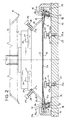
- the transfer head 12 is provided with a reciprocating motion, preferably in a vertical direction, between a first operating position in which, as shown in chain line in Fig. 2, it is spaced apart from the bending station 6, in alignment therewith, and a second operating position in which, as shown in solid line in Figs. 2 and 3, operates on leaflet 5 so as to fold over the side flaps 5b thereof in cooperation with the bending means 13.
- the transfer head 12 has a base surface 14 facing the bending station 6 and arranged to act on the base portion 5a of leaflet 5, as well as at least one tapering end portion 15 disposed peripherally relative to the base surface 14, along a side of the latter.
- two tapering end portions 15 are provided which are disposed laterally on opposite sides relative to the base surface 14.
- the tapering end portions 15 have an orientation diverging obliquely from the movement direction of the transfer head 12 and project from the base surface 14 in the movement direction of the head itself towards the second operating position.
- the tapering end portions 15 are mutually spaced apart by a distance lower than the linear extension of leaflet 5. Therefore, when leaflet 5 is positioned on the support housings 11 arranged in the bending station 6, the leaflet side flaps 5b project laterally relative to the tapering end portions 15 of the transfer head 12.
- the transfer head 12 During its translation from the first to the second operating position, the transfer head 12 brings the extremities of the tapering end portions 15 into contact with leaflet 5. This contact takes place along the bending lines according to which the side flaps 5b of leaflet 5 will be then folded over.
- suction-cup elements or similar suction means converging on the base surface 14 of the transfer head 12 and not shown as known per se and conventional, carry out adhesion of the base portion 5a of leaflet 5, against the base surface 14. Projection of the tapering end portions 15 relative to the base surface 14 forces leaflet 5, under this circumstance, to take an arch-shaped configuration, as can be viewed from Figs. 2, 3 and 4.
- the tapering end portions 15 interact with the bending means 13 to cause bending of the side flaps 5b.
- the bending means comprises at least one preforming edge 16, and more specifically a pair of preforming edges 16, each of which is arranged to cooperate with the corresponding tapering end portion 15 to bend the leaflet side flap 5b substantially at an angle of 90°.
- each preforming edge 16 and the corresponding tapering end portion 15 is such arranged that a gauged passage of a width substantially corresponding to or slightly greater than the leaflet 5 thickness is defined between them.
- each preforming edge 16 at its upper part defines one of the support housings 11. Therefore, cooperation between the tapering end portions 15 and the preforming edges 16 occurs as soon as the tapering portions go down to a lower level than the lying plane of leaflet 5 on the support housings 11.
- each forming element 17 Arranged adjacent to the preforming edges 16 are respective forming elements 17 each intended for cooperation with one of the tapering end portions 15 when head 12 reaches the second operating position.
- each forming element 17 is provided with at least one coupling seating 18 extending in vertical alignment with the tapering end portion 15, so that the tapering end portion engages the coupling seating 18 when the transfer head 12 is about to reach its second operating position.
- each forming element 17 is essentially defined by a cylindrical body rotatably engaged in the bending station 6 according to its geometric rotation axis, disposed at a position laterally spaced away from the transfer head 12 relative to the extremity of the tapering end portion 15.
- the coupling seating 18 is advantageously defined by a groove of rectangular profile extending along a generatrix of the cylindrical body 17.
- the coupling seating 18 has a first locating edge 18a adapted to act in interference relationship on an inner side 15a of the tapering end portion 15 when, following descent of the transfer head 12 to the second operating position, the end portion 15 enters groove 18.
- a second locating edge 18b of the groove forming the coupling seating 18 is brought into abutment relationship against an outer side 15b of the tapering end portion 15, on the laterally opposite side relative to the first locating edge 18a, thereby causing a net bending of the side flap 5b about the extremity of the tapering end portion 15.
- each forming element 17 takes place against the action of at least one torsion spring 19 or equivalent return spring means that, in cooperation with stop pegs 19a, 19b located on the forming element 17 and a fixed portion of the bending station 6 respectively, carry out new positioning of the coupling seating 18 in alignment with the extremity of the tapering end portion 15 when the transfer head 12 is moved away again from the second operating position.
- Movement of the transfer head 12 on reaching of the second operating position is stopped by one or more stop elements 20 engaged in the bending station 6 and acting in abutment relationship against the base surface 14 of the transfer head itself.
- first adjustment means 21 Associated with the stop elements 20 is first adjustment means 21 by which a careful adjustment of the limit stroke of the transfer head 12 in the second operating position can be carried out.
- each stop means 20 be fastened to an end of a screw-threaded rod 22 operatively engaged in a screw-threaded hole 22a arranged in the bending station.
- a locking nut 22b enables a steady fastening of the respective stop element 20 to the desired position.
- the location at which the transfer head 12 is stopped in the second operating position and, as a result, the amount of the angular rotation imparted to the forming elements 17, can be advantageously adapted to the typology and thickness of the paper forming leaflet 5.
- stopping of the transfer head 12 in the second operating position can be advantageously adjusted in such a manner that, independently of the type and thickness of the paper forming leaflet 5, the side flaps 5b are folded over at an angle greater than 90°, so that said flaps, by effect of the material elasticity, spontaneously take an orientation of substantially 90° relative to the base portion 5a when, following the transfer head 12 return to the first operating position, the tapering end portions 15 disengage from the bending means 13.
- transfer means that carries out transferring of the bent leaflet 5 from the bending station 6 to a laying-down station 23 disposed along the packaging line 4.
- this transferring means consists of the same transfer head 12, the latter being mounted on a handling arm 24 carrying out translation thereof in a horizontal direction or in any case perpendicularly to the movement direction of the first and second operating positions.
- the transfer head 12 upon command of the handling arm 24 (only partly shown in Fig. 1 in that it can be made in a manner known per se and conventional), the transfer head 12 is brought from the first operating position to a third operating position in which, as shown in chain line in Fig. 4, it is disposed in alignment with a box-shaped casing 25 being part of a disc case 3, spaced apart from said box-shaped casing itself.
- the transfer head 12 Once the transfer head 12 has reached its third operating position, it performs a vertical stroke to a fourth operating position in which leaflet 5 in engagement therewith is inserted into the box-shaped casing 25.
- each of the tapering end portions 15 is formed on a plate-like element 26 oscillatably engaged with a corresponding side of the transfer head 12.
- the plate-like element 26 has, on an opposite side from the tapering end portion 15, an end edge 26a operatively engaged in a constraint housing defined between the corresponding side wall of the transfer head 12 and a locating block 27 fastened to said head.
- One or more springs or equivalent counter spring means 28 act between locating elements 29 fixedly carried by the transfer head 12 and the plate-like element 26 to keep the latter laterally urged against the transfer head.
- positioning of the tapering end portions 15 relative to the transfer head 12 can be adjusted, depending on the type and thickness of the paper forming leaflet 5 for example, as well as depending on the sizes of the box-shaped casing.
- each of the locating blocks 27 can be positioned longitudinally relative to the transfer head 12, said block being removably fastened to said head by screw-threaded locking elements 30 operating through respective elongated holes 30a arranged in the locating elements.
- Rest housings 27a for the end edges 26a of the plate-like elements 26 are defined by inclined surfaces, so that following a longitudinal displacement of the locating block 27, a displacement of the plate-like element 26 in its lying plane is obtained, which will bring the tapering end portion 15 to project to a more or less important degree relative to the base surface of the transfer head 12, thereby also adjusting width of the gauged passage defined with the respective preforming edge 16.
- Auxiliary elongated slide holes 31 arranged in each plate-like element 26 enable guided sliding of said element relative to the locating elements 29 carrying counter springs 28.
- the present invention achieves the intended purposes.
- the device in reference in fact has an excellent operating adaptability to any type of paper employed in making leaflets 5.
- Structure and operation of the forming elements 17 is such conceived that formation of perfect folds are ensured even in the absence of die cuttings on the leaflets being worked.
- mobility of the tapering end portions 15 ensures release of leaflet 5 into the casing 25, as well as positioning of the bent flaps 5b against the side walls 25b, also compensating for wide size tolerances in the casing itself.
Landscapes
- Engineering & Computer Science (AREA)
- Mechanical Engineering (AREA)
- Making Paper Articles (AREA)
- Auxiliary Devices For And Details Of Packaging Control (AREA)
Claims (16)
- Dispositif pour plier des notices et les transférer dans des boítes, comprenant:caractérisé en ce que lesdits moyens plieurs (13) comportent au moins un élément de formage (17) engagé à rotation dans le poste de pliage (6) et ayant au moins un siège d'accouplement (18) s'étendant parallèle à un axe de rotation de l'élément de formage, en alignement avec ladite portion terminale à section décroissante (15), pour l'engagement avec ladite portion terminale (15) par repliement du rabat (5b) de la notice autour de ladite portion terminale quand le tête (12) est amenée à ladite deuxième position de travail.un poste de pliage (6),des moyens d'alimentation (7) destinés à transférer au moins une notice (5) dans un poste de pliage (6),une tête de transport (12) mobile selon un mouvement alternatif entre une première position de travail dans laquelle elle est éloignée du poste de pliage (6) et en alignement avec ce dernier, et une deuxième position de travail dans laquelle elle agit sur la notice (5) arrangée au poste de pliage (6), ladite tête de transport ayant une surface de base (14) en regard du poste de pliage (6) et au moins une portion terminale à section décroissante (15) disposée à la périphérie par rapport à la surface de base,des moyens plieurs (13) agissant dans ledit poste de pliage (6) pour replier, en coopération avec la tête de transport (12), au moins un rabat latéral (5b) de la notice faisant saillie de ladite portion terminale (15),des moyens de transport pour transférer la notice pliée (5) du poste de pliage (6) à une boíte disposée dans un poste de dépôt (23),
- Dispositif selon la revendication 1, caractérisé en ce que ledit élément de formage (17) comporte un corps cylindrique engagé à rotation suivant son axe géométrique dans le poste de pliage (6) et pourvu d'au moins une rainure s'étendant le long de sa génératrice pour définir ledit siège d'accouplement (18).
- Dispositif selon la revendication 2, caractérisé en ce que ledit siège d'accouplement (18) a un premier bord de butée (18a) agissant par interférence sur un côté intérieur (15a) de ladite portion terminale à section décroissante (15) pour causer une rotation angulaire de l'élément de formage (17) quand la tête de transport (12) atteint la deuxième position de travail, et un second bord de butée (18b) agissant contre un côté extérieur (15b) de la portion terminale à section décroissante (15) sur le côté latéralement opposé par rapport audit premier bord de butée (18a), à la suite de la rotation effectuée par l'élément de formage (17).
- Dispositif selon la revendication 1, caractérisé en ce qu'il comporte en outre des moyens élastiques de rappel (19) agissant contre la rotation de l'élément de formage (17).
- Dispositif selon la revendication 1, caractérisé en ce que lesdits moyens plieurs (13) comportent en outre au moins un bord de pré-formage (16) s'étendant à proximité de l'élément de formage (17) et destiné à coopérer avec ladite portion terminale à section décroissante (15) pour plier le rabat (5b) de la notice avant l'engagement de la portion terminale avec l'élément de formage (17).
- Dispositif selon la revendication 5, caractérisé en ce que ledit au moins un bord de pré-formage définit un siège de support (11) pour soutenir la notice (5) à une position d'interférence entre la tête de transport (12) disposée à la première position de travail et lesdits moyens plieurs (13).
- Dispositif selon la revendication 1, comprenant en outre au moins un élément d'arrêt (20) agissant sur la tête de transport (12) pour arrêter le mouvement en avant de ladite tête vers la deuxième position de travail, des moyens de réglage (21) étant associés audit élément d'arrêt (20) pour régler la position d'arrêt de la tête de transport (12) à la deuxième position de travail.
- Dispositif selon la revendication 1, caractérisé en ce que ladite portion terminale à section décroissante (15) fait saillie de la surface de base dans la direction de mouvement de la tête de transport (12) vers la deuxième position de travail.
- Dispositif selon la revendication 8, caractérisé en ce que la portion terminale à section décroissante (15) a une orientation divergeant obliquement de la direction de mouvement de la tête de transport (12) entre les première et deuxième positions de travail.
- Dispositif selon la revendication 8, caractérisé en ce que ladite portion terminale à section décroissante (15) est formée sur un élément en forme de plaque (26) en engagement amovible avec la tête de transport (12).
- Dispositif selon la revendication 10, caractérisé en ce que la portion terminale (15) peut être écartée latéralement de la surface de base (14) contre l'action de moyens élastiques antagonistes (28).
- Dispositif selon la revendication 11, caractérisé en ce que lesdits moyens élastiques antagonistes (28) agissent entre des éléments de butée (29) portés rigidement par la portion principale de la tête de transport et ledit élément en forme de plaque, ce dernier élément étant lié de manière oscillante à une paroi latérale de la portion principale elle-même.
- Dispositif selon la revendication 10, caractérisé en ce qu'il comporte en outre des moyens de réglage pour fixer la mise en place de l'élément en forme de plaque (26) sur la tête de transport (12).
- Dispositif selon la revendication 13, caractérisé en ce que lesdits moyens de réglage comportent au moins un bloc de butée (27) ayant un plan d'appui incliné (27a) sur lequel agit un bord terminal (26a) de l'élément en forme de plaque (26) opposé à ladite portion terminale à section décroissante (15), ledit bloc de butée (27) étant destiné à être positionné sélectivement sur ladite tête dans le but de modifier la mise en place de la portion terminale à section décroissante (15).
- Dispositif selon la revendication 1, caractérisé en ce que lesdits moyens de transport se composent essentiellement de la tête de transport (12), cette tête étant mobile perpendiculairement à la direction de mouvement entre ses première et deuxième positions de travail pour transférer ladite notice (5) du poste de pliage (6) à un poste de dépôt (23).
- Dispositif selon la revendication 15, caractérisé en ce que dans le poste de dépôt (23) la tête de transport (12) est mobile d'une troisième position de travail à une quatrième position de travail pour déposer la notice pliée (5) dans une boíte (25).
Priority Applications (5)
| Application Number | Priority Date | Filing Date | Title |
|---|---|---|---|
| EP97830357A EP0895932B1 (fr) | 1997-07-16 | 1997-07-16 | Dispositif pour plier des notices et pour transférer celles-ci dans des boítes |
| DE69704113T DE69704113T2 (de) | 1997-07-16 | 1997-07-16 | Vorrichtung zum Falten von Beipackzetteln, und zum Überführen derselben in Schachteln |
| AT97830357T ATE199233T1 (de) | 1997-07-16 | 1997-07-16 | Vorrichtung zum falten von beipackzetteln, und zum überführen derselben in schachteln |
| US09/095,622 US6035605A (en) | 1997-07-16 | 1998-06-10 | Device for bending and transferring leaflets into box-shaped casings |
| CA002242832A CA2242832A1 (fr) | 1997-07-16 | 1998-07-02 | Dispositif de pliage et d'insertion de feuillets dans des boitiers |
Applications Claiming Priority (1)
| Application Number | Priority Date | Filing Date | Title |
|---|---|---|---|
| EP97830357A EP0895932B1 (fr) | 1997-07-16 | 1997-07-16 | Dispositif pour plier des notices et pour transférer celles-ci dans des boítes |
Publications (2)
| Publication Number | Publication Date |
|---|---|
| EP0895932A1 EP0895932A1 (fr) | 1999-02-10 |
| EP0895932B1 true EP0895932B1 (fr) | 2001-02-21 |
Family
ID=8230708
Family Applications (1)
| Application Number | Title | Priority Date | Filing Date |
|---|---|---|---|
| EP97830357A Expired - Lifetime EP0895932B1 (fr) | 1997-07-16 | 1997-07-16 | Dispositif pour plier des notices et pour transférer celles-ci dans des boítes |
Country Status (5)
| Country | Link |
|---|---|
| US (1) | US6035605A (fr) |
| EP (1) | EP0895932B1 (fr) |
| AT (1) | ATE199233T1 (fr) |
| CA (1) | CA2242832A1 (fr) |
| DE (1) | DE69704113T2 (fr) |
Families Citing this family (12)
| Publication number | Priority date | Publication date | Assignee | Title |
|---|---|---|---|---|
| JP4031169B2 (ja) * | 2000-01-14 | 2008-01-09 | 株式会社京都製作所 | 表題紙挿入方法および表題紙挿入装置 |
| IT1320882B1 (it) * | 2000-02-18 | 2003-12-10 | Miri Srl | Metodo ed apparato per l'alimentazione di custodie per dvd o per cd,originariamente vuote e chiuse, a mezzi per l'apertura, per la |
| JP4146599B2 (ja) * | 2000-03-31 | 2008-09-10 | 株式会社京都製作所 | 冊子の挿入方法および挿入装置 |
| WO2002012069A1 (fr) * | 2000-08-07 | 2002-02-14 | Dsd Communications, Inc. | Systeme et procede permettant d'ajouter des encarts a des articles durant un empaquetage automatise |
| US6584753B2 (en) * | 2000-08-07 | 2003-07-01 | Dsd Communications, Inc. | System and method for including inserts with goods during automated packaging |
| US6993887B2 (en) | 2000-08-07 | 2006-02-07 | Dsd Communications, Inc. | System and method for including packets with goods during automated packaging |
| US20020100254A1 (en) * | 2000-10-12 | 2002-08-01 | Dsd Communications, Inc. | System and method for targeted advertising and marketing |
| ITBO20000654A1 (it) * | 2000-11-14 | 2002-05-14 | Sichera Di Sichera Gianni | Macchina per il confezionamento di articoli, in particolare cd, dvd esimili, in relativi contenitori |
| US6898923B2 (en) | 2001-06-11 | 2005-05-31 | Sagoma Plastics Corporation | Disc packaging |
| US6557320B2 (en) * | 2001-08-31 | 2003-05-06 | Chen Hsien Chang | Compact disk packing machine |
| US6732492B2 (en) * | 2002-07-23 | 2004-05-11 | Potlatch Corporation | Methods of packaging paper products |
| US7089712B2 (en) * | 2004-05-18 | 2006-08-15 | The Form House, Inc. | Apparatus and method for producing a DVD carrier assembly |
Family Cites Families (10)
| Publication number | Priority date | Publication date | Assignee | Title |
|---|---|---|---|---|
| US4283190A (en) * | 1977-04-12 | 1981-08-11 | Williams Donald F | Method for forming paper boxes and the like |
| DE3536509A1 (de) * | 1985-10-12 | 1987-04-16 | Ilsemann Heino | Verfahren und vorrichtung zum einbringen von compact-discs (cd) in cd-boxen |
| DE3643693C1 (de) * | 1986-12-20 | 1988-02-11 | Philips & Du Pont Optical | Assemblierungsmaschine fuer eine Verpackung |
| US5163271A (en) * | 1992-01-15 | 1992-11-17 | Thiele Engineering Company | Apparatus and method for manufacturing compact disc holders |
| US5207050A (en) * | 1992-01-15 | 1993-05-04 | Thiele Engineering Company | Apparatus and method for assembling compact disc or media package |
| US5285620A (en) * | 1992-12-11 | 1994-02-15 | Thiele Engineering Company | Apparatus and method for manufacturing a compact disc holder |
| US5341624A (en) * | 1992-12-30 | 1994-08-30 | Thiele Engineering Co. | Panel placer |
| EP0725006B1 (fr) * | 1995-01-26 | 1997-05-14 | TAPEMATIC S.p.A. | Procédé et appareil pour emballer des disques compacts dans leurs boîtes respectives |
| US5816028A (en) * | 1995-06-14 | 1998-10-06 | Gima S.P.A. | Compact disc packaging machine |
| US5788114A (en) * | 1996-01-25 | 1998-08-04 | Tapematic U.S.A., Inc. | CD packaging system and method including a case-feeding unit a unit for individually feeding brochures to a pickup station and an apparatus for packaging compact discs into respective cases |
-
1997
- 1997-07-16 DE DE69704113T patent/DE69704113T2/de not_active Expired - Fee Related
- 1997-07-16 AT AT97830357T patent/ATE199233T1/de not_active IP Right Cessation
- 1997-07-16 EP EP97830357A patent/EP0895932B1/fr not_active Expired - Lifetime
-
1998
- 1998-06-10 US US09/095,622 patent/US6035605A/en not_active Expired - Fee Related
- 1998-07-02 CA CA002242832A patent/CA2242832A1/fr not_active Abandoned
Also Published As
| Publication number | Publication date |
|---|---|
| EP0895932A1 (fr) | 1999-02-10 |
| DE69704113D1 (de) | 2001-03-29 |
| US6035605A (en) | 2000-03-14 |
| DE69704113T2 (de) | 2001-06-07 |
| ATE199233T1 (de) | 2001-03-15 |
| CA2242832A1 (fr) | 1999-01-16 |
Similar Documents
| Publication | Publication Date | Title |
|---|---|---|
| EP0895932B1 (fr) | Dispositif pour plier des notices et pour transférer celles-ci dans des boítes | |
| SU818473A3 (ru) | Устройство дл нанесени этикеток | |
| EP1775223B1 (fr) | Station pour retirer et ériger les boîtes tubulaires pliées plats | |
| US3953020A (en) | Bag aligner machine | |
| JPS62122906A (ja) | Cd箱の中にcdを収容する方法とその装置 | |
| US6718728B2 (en) | Packing machine | |
| GB1462817A (en) | Apparatus and method for orienting and case packing eared containers | |
| CZ253493A3 (en) | Device for folding parts of a cardboard half-finished product bottom | |
| CN110027749A (zh) | 一种自动化盒装设备、封口装置及其盒盖压折机构 | |
| JP6571449B2 (ja) | 封緘機 | |
| CA1058231A (fr) | Dispositif pour regler le degre d'inclinaison d'ebauches de cartonnage | |
| US7287360B2 (en) | Bottom taping system using a pusher feed | |
| JPS6238205B2 (fr) | ||
| JPS62255128A (ja) | 包装機械における装置 | |
| JP3577784B2 (ja) | 物品および紙片の挿入装置 | |
| US5152124A (en) | Apparatus for filling and sealing bags | |
| US5613932A (en) | Apparatus for transporting hinge-lid boxes for cigarettes | |
| EP1136404A2 (fr) | Dispositif pour l'alignement longitudinal d'éléments en plaques dans une station d'introduction d'une machine les travaillant | |
| CN114476171A (zh) | 用于在不同形式的箱上安置盖的机器 | |
| JPH09249201A (ja) | カートンの蓋閉装置 | |
| US4116428A (en) | Apparatus for separating lowermost sheets from a stack | |
| EP0472182A1 (fr) | Appareil pour ériger des ébauches de boîtes | |
| JP4705289B2 (ja) | 段ボール箱のフラップ折込み方法及び装置 | |
| US3041943A (en) | Box making machine | |
| GB2251202A (en) | Apparatus and method for moulding and assembling plastic cassette case parts |
Legal Events
| Date | Code | Title | Description |
|---|---|---|---|
| PUAI | Public reference made under article 153(3) epc to a published international application that has entered the european phase |
Free format text: ORIGINAL CODE: 0009012 |
|
| 17P | Request for examination filed |
Effective date: 19980401 |
|
| AK | Designated contracting states |
Kind code of ref document: A1 Designated state(s): AT DE ES FR GB IT NL |
|
| AX | Request for extension of the european patent |
Free format text: AL;LT;LV;RO;SI |
|
| AKX | Designation fees paid |
Free format text: AT DE ES FR GB IT NL |
|
| GRAG | Despatch of communication of intention to grant |
Free format text: ORIGINAL CODE: EPIDOS AGRA |
|
| GRAG | Despatch of communication of intention to grant |
Free format text: ORIGINAL CODE: EPIDOS AGRA |
|
| GRAH | Despatch of communication of intention to grant a patent |
Free format text: ORIGINAL CODE: EPIDOS IGRA |
|
| 17Q | First examination report despatched |
Effective date: 20001020 |
|
| GRAH | Despatch of communication of intention to grant a patent |
Free format text: ORIGINAL CODE: EPIDOS IGRA |
|
| GRAA | (expected) grant |
Free format text: ORIGINAL CODE: 0009210 |
|
| ITF | It: translation for a ep patent filed | ||
| AK | Designated contracting states |
Kind code of ref document: B1 Designated state(s): AT DE ES FR GB IT NL |
|
| PG25 | Lapsed in a contracting state [announced via postgrant information from national office to epo] |
Ref country code: NL Free format text: LAPSE BECAUSE OF FAILURE TO SUBMIT A TRANSLATION OF THE DESCRIPTION OR TO PAY THE FEE WITHIN THE PRESCRIBED TIME-LIMIT Effective date: 20010221 Ref country code: ES Free format text: THE PATENT HAS BEEN ANNULLED BY A DECISION OF A NATIONAL AUTHORITY Effective date: 20010221 Ref country code: AT Free format text: LAPSE BECAUSE OF FAILURE TO SUBMIT A TRANSLATION OF THE DESCRIPTION OR TO PAY THE FEE WITHIN THE PRESCRIBED TIME-LIMIT Effective date: 20010221 |
|
| REF | Corresponds to: |
Ref document number: 199233 Country of ref document: AT Date of ref document: 20010315 Kind code of ref document: T |
|
| ET | Fr: translation filed | ||
| REF | Corresponds to: |
Ref document number: 69704113 Country of ref document: DE Date of ref document: 20010329 |
|
| PGFP | Annual fee paid to national office [announced via postgrant information from national office to epo] |
Ref country code: GB Payment date: 20010711 Year of fee payment: 5 |
|
| PGFP | Annual fee paid to national office [announced via postgrant information from national office to epo] |
Ref country code: FR Payment date: 20010731 Year of fee payment: 5 |
|
| NLV1 | Nl: lapsed or annulled due to failure to fulfill the requirements of art. 29p and 29m of the patents act | ||
| PLBE | No opposition filed within time limit |
Free format text: ORIGINAL CODE: 0009261 |
|
| STAA | Information on the status of an ep patent application or granted ep patent |
Free format text: STATUS: NO OPPOSITION FILED WITHIN TIME LIMIT |
|
| REG | Reference to a national code |
Ref country code: GB Ref legal event code: IF02 |
|
| 26N | No opposition filed | ||
| PG25 | Lapsed in a contracting state [announced via postgrant information from national office to epo] |
Ref country code: GB Free format text: LAPSE BECAUSE OF NON-PAYMENT OF DUE FEES Effective date: 20020716 |
|
| GBPC | Gb: european patent ceased through non-payment of renewal fee |
Effective date: 20020716 |
|
| PG25 | Lapsed in a contracting state [announced via postgrant information from national office to epo] |
Ref country code: FR Free format text: LAPSE BECAUSE OF NON-PAYMENT OF DUE FEES Effective date: 20030331 |
|
| REG | Reference to a national code |
Ref country code: FR Ref legal event code: ST |
|
| PGFP | Annual fee paid to national office [announced via postgrant information from national office to epo] |
Ref country code: DE Payment date: 20040729 Year of fee payment: 8 |
|
| PG25 | Lapsed in a contracting state [announced via postgrant information from national office to epo] |
Ref country code: IT Free format text: LAPSE BECAUSE OF NON-PAYMENT OF DUE FEES;WARNING: LAPSES OF ITALIAN PATENTS WITH EFFECTIVE DATE BEFORE 2007 MAY HAVE OCCURRED AT ANY TIME BEFORE 2007. THE CORRECT EFFECTIVE DATE MAY BE DIFFERENT FROM THE ONE RECORDED. Effective date: 20050716 |
|
| PG25 | Lapsed in a contracting state [announced via postgrant information from national office to epo] |
Ref country code: DE Free format text: LAPSE BECAUSE OF NON-PAYMENT OF DUE FEES Effective date: 20060201 |