EP0896097A1 - Einbaubare Leuchtmarkierung für Autobahnen und Strassen - Google Patents
Einbaubare Leuchtmarkierung für Autobahnen und Strassen Download PDFInfo
- Publication number
- EP0896097A1 EP0896097A1 EP98402019A EP98402019A EP0896097A1 EP 0896097 A1 EP0896097 A1 EP 0896097A1 EP 98402019 A EP98402019 A EP 98402019A EP 98402019 A EP98402019 A EP 98402019A EP 0896097 A1 EP0896097 A1 EP 0896097A1
- Authority
- EP
- European Patent Office
- Prior art keywords
- translucent
- blocks
- block
- cavity
- links
- Prior art date
- Legal status (The legal status is an assumption and is not a legal conclusion. Google has not performed a legal analysis and makes no representation as to the accuracy of the status listed.)
- Withdrawn
Links
- 239000013307 optical fiber Substances 0.000 claims abstract description 37
- 239000000835 fiber Substances 0.000 claims abstract description 29
- 239000000463 material Substances 0.000 claims abstract description 10
- 229920000728 polyester Polymers 0.000 claims abstract description 6
- 229920002635 polyurethane Polymers 0.000 claims abstract description 5
- 239000004814 polyurethane Substances 0.000 claims abstract description 5
- 239000004033 plastic Substances 0.000 claims abstract description 4
- 229920003023 plastic Polymers 0.000 claims abstract description 4
- 239000011521 glass Substances 0.000 claims abstract description 3
- 239000004567 concrete Substances 0.000 claims description 10
- 239000002131 composite material Substances 0.000 claims description 9
- 239000002184 metal Substances 0.000 claims description 7
- 238000010276 construction Methods 0.000 claims description 5
- 210000004907 gland Anatomy 0.000 claims description 4
- 239000003550 marker Substances 0.000 abstract 2
- 230000008878 coupling Effects 0.000 abstract 1
- 238000010168 coupling process Methods 0.000 abstract 1
- 238000005859 coupling reaction Methods 0.000 abstract 1
- 230000004907 flux Effects 0.000 description 6
- 230000004888 barrier function Effects 0.000 description 4
- 230000003287 optical effect Effects 0.000 description 4
- 238000004873 anchoring Methods 0.000 description 3
- 230000008901 benefit Effects 0.000 description 3
- 230000011664 signaling Effects 0.000 description 3
- 239000004575 stone Substances 0.000 description 3
- 230000006978 adaptation Effects 0.000 description 2
- 239000010426 asphalt Substances 0.000 description 2
- 239000011159 matrix material Substances 0.000 description 2
- 230000035515 penetration Effects 0.000 description 2
- 230000001681 protective effect Effects 0.000 description 2
- 241001639412 Verres Species 0.000 description 1
- 230000005465 channeling Effects 0.000 description 1
- 229910052736 halogen Inorganic materials 0.000 description 1
- 150000002367 halogens Chemical class 0.000 description 1
- 230000010354 integration Effects 0.000 description 1
- 238000012423 maintenance Methods 0.000 description 1
- 238000004519 manufacturing process Methods 0.000 description 1
- 239000000203 mixture Substances 0.000 description 1
- 230000000149 penetrating effect Effects 0.000 description 1
- 239000013308 plastic optical fiber Substances 0.000 description 1
- 238000007789 sealing Methods 0.000 description 1
- 230000035939 shock Effects 0.000 description 1
- 230000032258 transport Effects 0.000 description 1
- 239000002023 wood Substances 0.000 description 1
Images



Classifications
-
- E—FIXED CONSTRUCTIONS
- E01—CONSTRUCTION OF ROADS, RAILWAYS, OR BRIDGES
- E01C—CONSTRUCTION OF, OR SURFACES FOR, ROADS, SPORTS GROUNDS, OR THE LIKE; MACHINES OR AUXILIARY TOOLS FOR CONSTRUCTION OR REPAIR
- E01C17/00—Pavement lights, i.e. translucent constructions forming part of the surface
-
- E—FIXED CONSTRUCTIONS
- E01—CONSTRUCTION OF ROADS, RAILWAYS, OR BRIDGES
- E01F—ADDITIONAL WORK, SUCH AS EQUIPPING ROADS OR THE CONSTRUCTION OF PLATFORMS, HELICOPTER LANDING STAGES, SIGNS, SNOW FENCES, OR THE LIKE
- E01F9/00—Arrangement of road signs or traffic signals; Arrangements for enforcing caution
- E01F9/20—Use of light guides, e.g. fibre-optic devices
-
- E—FIXED CONSTRUCTIONS
- E01—CONSTRUCTION OF ROADS, RAILWAYS, OR BRIDGES
- E01F—ADDITIONAL WORK, SUCH AS EQUIPPING ROADS OR THE CONSTRUCTION OF PLATFORMS, HELICOPTER LANDING STAGES, SIGNS, SNOW FENCES, OR THE LIKE
- E01F9/00—Arrangement of road signs or traffic signals; Arrangements for enforcing caution
- E01F9/50—Road surface markings; Kerbs or road edgings, specially adapted for alerting road users
- E01F9/535—Kerbs or road edgings specially adapted for alerting road users
- E01F9/547—Kerbs or road edgings specially adapted for alerting road users illuminated
-
- E—FIXED CONSTRUCTIONS
- E01—CONSTRUCTION OF ROADS, RAILWAYS, OR BRIDGES
- E01F—ADDITIONAL WORK, SUCH AS EQUIPPING ROADS OR THE CONSTRUCTION OF PLATFORMS, HELICOPTER LANDING STAGES, SIGNS, SNOW FENCES, OR THE LIKE
- E01F9/00—Arrangement of road signs or traffic signals; Arrangements for enforcing caution
- E01F9/60—Upright bodies, e.g. marker posts or bollards; Supports for road signs
- E01F9/658—Upright bodies, e.g. marker posts or bollards; Supports for road signs characterised by means for fixing
- E01F9/669—Upright bodies, e.g. marker posts or bollards; Supports for road signs characterised by means for fixing for fastening to safety barriers or the like
Definitions
- the present invention relates to a beaconing device light point of works or parts of civil engineering works, buildings and / or public works, and / or works truckers.
- the technical sector of the invention is the field of construction of roads and urban development works or highway.
- the present invention applies in particular to point marking bright directional islands, roundabouts, turns, crossings pedestrians across traffic lanes, speed bumps or speed bumps, pedestrian walkways, sidewalks, squares, playgrounds or areas petrol stations, bus stops, motorway tolls, as well as light signaling for traffic lanes equipped with runners especially security.
- Patent application No. FR 2,686,104 describes a device safety and signaling light for traffic lanes.
- the device consists of a luminous composite plate molded, which is connected to a light emission box by a cable optics; the plate is fixed temporarily or permanently in across a traffic lane, contains bundles of fibers plastic optics grouped in an optical cable which connects the plate to an emission box comprising for example a halogen lamp focused; the optical fibers are leveled off at the edge of the plate and continuously or intermittently deliver light signals under form of tasks to form letters or a luminous message.
- the object of the present invention is to provide a device light using a light generator connected to a beam of fiber optics, which is improved.
- An objective of the present invention is to improve protection ends of optical fibers used in this type of structure.
- An objective of the invention is to facilitate the implementation practical and fast of such a system and its integration into different types urban or road development works in particular.
- the solution to the problem posed consists in providing a device for lighting of a civil engineering structure, which includes a beam sections of optical fibers connected to a light generator, in which one end of each section of optical fiber is housed in a cavity of a block or element at least partly translucent or transparent, which is fixed or integrated into the structure.
- the ends of the optical fibers benefit mechanical protection and protection against impact resulting the presence of the block or diffusing element partially covering the minus the end of the optical fiber; thanks to the fact that the end of the optical fiber is housed in a cavity of the block, we obtain a protection of the end of the optical fiber against dirt; in in addition, thermal protection of the optical fiber is favored by avoiding accidental contact of it with hot materials usually used when making track surfaces in particular, namely products based on aggregates and bitumen type "Coated".
- a block or translucent element allows to transmit to the outside of the work or construction, by at least part of one of its sides, the light flux coming from the light generator and transmitted by the section of optical fiber.
- the invention consists in proposing a work civil engineering or road or urban development (such as slides) incorporating a beacon device according to the invention.
- a result of the invention is to improve the road safety of at night, in foggy and / or rainy weather by creating punctual markup luminous inserted in traditional concrete or coated structures.
- a result of the invention is to make it more visible at night, or in rain or fog, areas of roadways or motorways, channeled by metal or wood or concrete slides, such as turns, entrances to rest areas, exit ramps.
- a result of the invention is to report an obstacle or a demarcation of road or motorway lane by light signs - fixed or intermittent - orange-colored, non-blinding, which is integrated at a security gate.
- the turn or the obstacle is visible in its all, regardless of the existence and position of the lighthouses of vehicles, and safely, unlike known systems of signaling by "flash lights” which have the disadvantage of dazzling and whose the power supply is a danger in the event of an impact with the parts metallic.
- the present invention provides a point marking device luminous adaptable to any type of traffic lane delimitation road or pedestrian.
- a result of the invention is to improve the visibility of obstacles at risk, to attract the attention of motorists passing or waiting for pedestrians and channeling the pedestrian crossing roads or pedestrian walkways, especially for children.
- the device may include a block or element made of semi-rigid composite (polyurethane or other) translucent hollowed out, molded in the shape of a paver, border or other depending on the adaptation and tinted in the mass.
- This block is connected to a light generator by a fiber cable optical.
- This light block is sealed or glued and is part of a together at the edge or across a road or pedestrian.
- a device may include hollow elements in translucent composite flexible material (polyurethane or polyester), tinted (orange) in the mass, fixed by metal legs on or to the inside of the safety barriers or barriers and supplied by fiber optic cables attached behind the slide or barrier security ; this optical fiber carrying only light, does not presents no electrical risk in the event of an impact with the obstacle.
- optical fibers are inserted inside the composite block in a cavity provided for this purpose and protecting the end of the fiber optics for dirt, shocks, humidity and contacts accidental with hot materials usually used when manufacture of track coverings such as asphalt of the "coated" type.
- the routing of optical fibers between the generator and the blocks can take place in sheaths along the concrete structures.
- the generator can be installed, depending on the environment, either recessed to the ground in a manhole, either in a metal base box or polyester on sidewalk, or built into a wall box fencing.
- This generator can transmit in blocks or elements translucent, via optical fibers, a luminous flux continuously or intermittently to create markup at night visible by vehicles or pedestrians.
- the device of the present invention allows, depending on the direction penetration of the optical fiber into the block or translucent element, to emit a luminous flux on the visible face of the block which is in the extension of existing complexes (such as pavers or curbs). As a result, the light flux is transmitted to the outside of the structure.
- each translucent element or block is adapted to the external shape, which facilitates the introduction and fixing the end of the optical fiber to the block or border translucent.
- optical fiber in the pavement or the border translucent is carried out either from below or in the side depending on the face to light up.
- the structure modular beaconing device promotes the adaptation of the device to very variable forms of different structures which can be equipped with the beaconing device according to the invention.
- Such devices can be obtained industrially at lower cost and be implemented quickly and therefore also at lower cost.
- the present invention makes it possible to use a single lamp for signal an obstacle with different light elements distributed over several meters or tens of meters, along a slide especially.
- Each of said translucent elements can be fixed on its support (metallic, wooden or concrete) by fixing lugs.
- the invention improves the optical effect of markup thanks to a relatively large area of emission of light flux towards the exterior of the structure, in comparison with the reduced surface of sections of optical fibers used.
- Figure 1 illustrates in simplified perspective view, the application from the invention to the marking of a raised pedestrian crossing, across a road traffic lane.
- Figure 2 is a plan view of the device of Figure 1.
- Figure 3 is a sectional view through a vertical plane of the same device and is a view along III / III of FIG. 2.
- Figure 4 illustrates in schematic perspective view a first embodiment of a translucent block used in the composition of a device according to the invention.
- Figures 5 and 6 illustrate in perspective view and in view side section a second embodiment of a translucent block hollow according to the invention in the form of a parallelepiped paving stone; the Figures 7 and 8 illustrate in perspective view and in side sectional view a third embodiment of a conformal hollow translucent block to the invention in the form of a border element; Figures 6 and 8 are respective views according to VI-VI and VIII-VIII of Figures 5 and 7.
- Figure 9 illustrates in simplified perspective view, the application from the invention to the marking of a bend or a road.
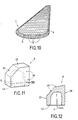
- Figure 10 illustrates in simplified perspective view the application from the invention to the marking of a directional or roundabout island road.
- Figures 11 and 12 illustrate a fourth embodiment of a hollow translucent block in accordance with the invention in the form of an element border similar to that shown in Figures 7 and 8.
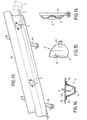
- FIGS 13 and 14 illustrate the application of the invention to marking of metal road safety barriers.
- FIGs 17 and 18 illustrate the application of the invention to road safety wooden runway signs
- Figures 13 and 17 are simplified perspective views while that Figures 14 and 18 are side views of the devices illustrated Figures 13 and 17.
- Figure 15 illustrates in schematic perspective view a hollow translucent element and its fixing lugs to a section of slide
- Figure 16 illustrates in top view the attachment of the element shown in Figure 15 to a section of slide.
- the passage pedestrian 7 extends along a longitudinal axis 35 perpendicular to the axis longitudinal 36 of pavement 30 of a road traffic lane; of border elements 32 separate the roadway 30 from the sidewalk 31, in which is housed a rectangular housing 33, for example prefabricated in concrete, receiving a light generator 3 powered by a source of electrical energy not shown.
- the housing 33 receiving the generator 3 is closed in its part upper by a protective plate 34 mounted flush with the sidewalk surface 31; in a variant embodiment not shown, the box 33 receiving the generator can be arranged on the sidewalk and / or integrated into the wall of a construction located close to the marked work; pedestrian crossing 7 has a plurality of blocks 13 opaque, of rectangular parallelepiped shape (or as a variant of substantially frustoconical shape, of square director or rectangular), arranged in rows and columns respectively parallel to axes 35 and 36; opaque concrete blocks 13 are connected between them, for example by overmolding, by first cables metallic 14 extending parallel to the axis 35, and by second metallic cables 17 extending parallel to the axis 36 (in FIG. 2, only two cables 14 and two cables 17 are shown to facilitate the readability of the figure; however the device preferably comprises as many cables 17 as columns of elements 13 and as many cables 14 than rows of elements 13).
- blocks or at least partially translucent paving stones 6, preferably in shape identical or similar to that of opaque blocks 13, the blocks translucent 6 being included in the matrix of the opaque blocks 13 and aligned with these; these translucent blocks 6 which are more precisely shown in Figures 4 to 8, each have a cavity 5 cylindrical, receiving the end 4 of a respective section 2 of fiber optical, which transports part of the light flux emitted by the light generator 3, from the generator to the translucent block diffusing 6; as illustrated particularly in figure 2, the sections of optical fibers 2 extend between the generator 3 and the blocks translucent 6 respective, forming a bundle (or strand of fibers) 1 to proximity to generator 3 which divides (and / or branches) nearby edges 32 (in the area of the structure forming a gutter); the end portions of bundle branches and fiber sections extend outside the pedestrian crossing 7, i.e. outside of the matrix of the blocks 13, to facilitate the maintenance of the device markup, that is to say without the need to destroy the structure of the passage pedestrian.
- the upper face 18 of the blocks 6 extends (flush) in the extension of the upper face 12 of the opaque blocks 13 of the structure 7.
- the translucent block 6 equipped with the cylindrical cavity 5 in the form of a blind hole receiving the end 4 of the optical fiber is of rectangular parallelepiped shape, delimited by side faces 38 square (or rectangular) and an upper face 18 square comprising at least one diffusing part 37, so that, thanks to the translucent nature of block 6 and the presence of part 18, 37 diffusing located in the upper part of it, the block can diffuse the light received from the fiber section 2 leading to the block 6, by example vertically along axis 39 or inclined relative to vertically, to allow lighting of the structure to be which the translucent block 6 is integrated.
- Block 6 has grooves 15 and 16 in the lower part extending along respective axes perpendicular to each other, which grooves 15 and 16 open onto the underside or base 42 block 6; in this way, the cables 14, 17 forming part of the prefabricated structure of the pedestrian crossing shown in Figures 1, 3 which comprises said opaque blocks 13 connected by said cables 14, 17, can extend inside the translucent blocks 6 which are set place after the prior establishment of the structure consisting of elements 13, 14 and 17; this also allows, when sealing the translucent block 6 by known means with the rest of the structure, to promote the joining or anchoring of the translucent block 6 by compared to the rest of the structure, thanks to the mechanical connection with cables 14 and 17.
- the end 4 of the diffuse optical fiber 2 when connected to the generator light, a light beam extending at an opening angle depending on the nature of the fiber and the material used for the realization of the translucent element 6; the end 4 of fiber 2 is secured to block 6, by a cable gland type device 8, screwed in a part of the cylindrical cavity 5 and exerting pressure around the end 4 of the optical fiber to hold it in place; the cavity 5 receiving the end 4 of the fiber is closed at one end longitudinal by a bottom wall 44; according to a variant no shown, the cavity 5 opens at its second end into a second cavity larger than cavity 5 and extending as an extension of it, so that you can insert into the second cavity, the end of a protective sheath for the section of fiber 2, surrounding said fiber section.
- the elements 6 of translucent borders (such as those illustrated in Figures 7 and 8) are interposed between the elements 13 of concrete curbs and form an integral part of the alignment of border.
- These light borders 6 are supplied with light by fiber penetrating optics (as illustrated in FIGS. 5 to 8) by a face side 38 of element 6 or else by its base 42.
- the luminous part 37 is the visible part of the road and provides limit security by its increased visibility due to its brightness.
- the translucent element 6 in composite material forming a thin-walled cover is fixed to the sections of slides 90 by lugs 92.
- Element 6 receives the end of an optical fiber 2 which extends along the metal slide 90 ( Figures 13 and 14).
- optical fiber 2 may walk in a sheath 99 buried at the bottom of the slide such that shown in figure 17.
- optical fibers will be connected to a generator 3 located behind the slides and placed in a box fixed to the ground or buried.
- the end of the optical fiber 2 can be fixed by cable gland on the slide 90 and oriented so as to illuminate the front face 98 of the translucent composite element 6.
- the end piece 4 of the optical fiber 2 can enter the translucent element 6 from the rear of the support 91 slide 90 when passing through a reservation (port 93) in the support 91 (stake or vertical stake) for slide 2 or in the slide.
- the end piece 4 of the fiber will therefore be directed towards the front face 98 of the translucent element 6.
Landscapes
- Engineering & Computer Science (AREA)
- Architecture (AREA)
- Civil Engineering (AREA)
- Structural Engineering (AREA)
- Road Signs Or Road Markings (AREA)
Applications Claiming Priority (4)
| Application Number | Priority Date | Filing Date | Title |
|---|---|---|---|
| FR9710357 | 1997-08-08 | ||
| FR9710357A FR2767186B1 (fr) | 1997-08-08 | 1997-08-08 | Dispositif de balisage lumineux |
| FR9712787A FR2767378B1 (fr) | 1997-08-08 | 1997-10-08 | Dispositif d'integration de balisage lumineux autoroutier et de chantier |
| FR9712787 | 1997-10-08 |
Publications (1)
| Publication Number | Publication Date |
|---|---|
| EP0896097A1 true EP0896097A1 (de) | 1999-02-10 |
Family
ID=26233748
Family Applications (1)
| Application Number | Title | Priority Date | Filing Date |
|---|---|---|---|
| EP98402019A Withdrawn EP0896097A1 (de) | 1997-08-08 | 1998-08-07 | Einbaubare Leuchtmarkierung für Autobahnen und Strassen |
Country Status (2)
| Country | Link |
|---|---|
| EP (1) | EP0896097A1 (de) |
| FR (1) | FR2767378B1 (de) |
Cited By (2)
| Publication number | Priority date | Publication date | Assignee | Title |
|---|---|---|---|---|
| WO2000028146A1 (en) * | 1998-11-05 | 2000-05-18 | Pas Ireneus Johannes Theodorus | Traffic element with illumination and transparent plastic component therefor with illumination means |
| WO2008001244A3 (en) * | 2006-06-23 | 2008-04-03 | Harun Aksoy | A stone |
Citations (7)
| Publication number | Priority date | Publication date | Assignee | Title |
|---|---|---|---|---|
| DE906939C (de) * | 1951-12-15 | 1955-05-09 | Wilhelm Ludowici Dr Ing | Betonbahn |
| US3750099A (en) * | 1972-03-17 | 1973-07-31 | R Proctor | Pacing system for conveyances |
| DE3200184A1 (de) * | 1982-01-07 | 1983-07-14 | Heinz 2120 Lüneburg Krebber | "zusammengefuegte, kleinteilig gegliederte betongelenkplatten". |
| GB2128664A (en) * | 1982-10-20 | 1984-05-02 | Sho Bond Const | Luminous indicating device for road markings |
| US4992914A (en) * | 1989-10-02 | 1991-02-12 | Heiss Charles E | Illuminated stepping stones |
| EP0539615A1 (de) * | 1991-10-29 | 1993-05-05 | Daito Sangyo Co., Ltd. | Verkehrsanzeigevorrichtung und Lichtquelle für diese Anzeigevorrichtung |
| FR2686104A1 (fr) | 1992-01-13 | 1993-07-16 | Le Noane Georges | Dispositif lumineux de securite et de signalisation pour voies de circulation. |
-
1997
- 1997-10-08 FR FR9712787A patent/FR2767378B1/fr not_active Expired - Fee Related
-
1998
- 1998-08-07 EP EP98402019A patent/EP0896097A1/de not_active Withdrawn
Patent Citations (7)
| Publication number | Priority date | Publication date | Assignee | Title |
|---|---|---|---|---|
| DE906939C (de) * | 1951-12-15 | 1955-05-09 | Wilhelm Ludowici Dr Ing | Betonbahn |
| US3750099A (en) * | 1972-03-17 | 1973-07-31 | R Proctor | Pacing system for conveyances |
| DE3200184A1 (de) * | 1982-01-07 | 1983-07-14 | Heinz 2120 Lüneburg Krebber | "zusammengefuegte, kleinteilig gegliederte betongelenkplatten". |
| GB2128664A (en) * | 1982-10-20 | 1984-05-02 | Sho Bond Const | Luminous indicating device for road markings |
| US4992914A (en) * | 1989-10-02 | 1991-02-12 | Heiss Charles E | Illuminated stepping stones |
| EP0539615A1 (de) * | 1991-10-29 | 1993-05-05 | Daito Sangyo Co., Ltd. | Verkehrsanzeigevorrichtung und Lichtquelle für diese Anzeigevorrichtung |
| FR2686104A1 (fr) | 1992-01-13 | 1993-07-16 | Le Noane Georges | Dispositif lumineux de securite et de signalisation pour voies de circulation. |
Cited By (2)
| Publication number | Priority date | Publication date | Assignee | Title |
|---|---|---|---|---|
| WO2000028146A1 (en) * | 1998-11-05 | 2000-05-18 | Pas Ireneus Johannes Theodorus | Traffic element with illumination and transparent plastic component therefor with illumination means |
| WO2008001244A3 (en) * | 2006-06-23 | 2008-04-03 | Harun Aksoy | A stone |
Also Published As
| Publication number | Publication date |
|---|---|
| FR2767378B1 (fr) | 2000-02-04 |
| FR2767378A1 (fr) | 1999-02-19 |
Similar Documents
| Publication | Publication Date | Title |
|---|---|---|
| EP0658655B1 (de) | Beleuchtungsanlage | |
| US20020006313A1 (en) | Traffic element with illumination and transparent plastic component designed therefor with illumination means | |
| EP0118323B1 (de) | An Fahrbahnteilern aus Beton anbringbare Vorrichtung zu deren Schutz und Sichtbarmachung | |
| GB2459003A (en) | Safety reflector | |
| EP1187955A1 (de) | Strassenmarkierung mit verbesserter sichtbarkeit bei tag | |
| EP0896097A1 (de) | Einbaubare Leuchtmarkierung für Autobahnen und Strassen | |
| FR2690468A1 (fr) | Plot de balisage. | |
| FR2767186A1 (fr) | Dispositif de balisage lumineux | |
| US8147082B2 (en) | Versatile safety reflectors | |
| FR2911946A1 (fr) | Dispositif lumineux en particulier pour la signalisation, l'ornement et l'eclairage | |
| FR2686104A1 (fr) | Dispositif lumineux de securite et de signalisation pour voies de circulation. | |
| EP1550771B1 (de) | Leuchtsignalanordnung für Stadt- oder Routenkreuzung | |
| EP0479693A1 (de) | Strassenbeleuchtungsverfahren und -vorrichtung mit horizontalem, auf die Rückseite der Fahrzeuge gerichtetem Lichtstrom | |
| FR2681088A1 (fr) | Dispositif d'acces pour permettre a un vehicule routier d'acceder a une voie souterraine de trafic routier situee a grande profondeur a partir d'une voie de surface ou vice-versa et voie ainsi equipee. | |
| FR2665465A1 (fr) | Dispositif de prevention pour la circulation routiere. | |
| KR102754442B1 (ko) | 합성수지제의 차량 정지목 | |
| BE1008889A6 (fr) | Catadioptres routiers. | |
| EP0406063B1 (de) | Synthetischer Pflasterstein und Kantenstütze aus diesen Steinen hergestellt | |
| EP2130974B1 (de) | Flüchtige Sicherheitsreflektoren | |
| EP0773325A1 (de) | Hergestellter Gegenstand zur Markierung von benachbarte Fläche von Fahrbahnen für Fahrzeuge, hauptsächlich sichtbar im Dunkeln | |
| FR2483976A1 (fr) | Plot de signalisation | |
| BE401554A (de) | ||
| FR2632815A1 (fr) | Amenagement pour protection d'arbre | |
| FR3158777A1 (fr) | Système de signalisation lumineuse au sol | |
| NL1011959C1 (nl) | Verkeerselement met verlichting en daarvoor bestemd lichtdoorlatend kunststofonderdeel met verlichtingsmiddelen. |
Legal Events
| Date | Code | Title | Description |
|---|---|---|---|
| PUAI | Public reference made under article 153(3) epc to a published international application that has entered the european phase |
Free format text: ORIGINAL CODE: 0009012 |
|
| AK | Designated contracting states |
Kind code of ref document: A1 Designated state(s): AT BE CH DE DK ES FI FR GB GR IE IT LI LU MC NL PT SE |
|
| AX | Request for extension of the european patent |
Free format text: AL;LT;LV;MK;RO;SI |
|
| 17P | Request for examination filed |
Effective date: 19990729 |
|
| AKX | Designation fees paid |
Free format text: AT BE CH DE DK ES FI FR GB GR IE IT LI LU MC NL PT SE |
|
| 17Q | First examination report despatched |
Effective date: 20021210 |
|
| GRAP | Despatch of communication of intention to grant a patent |
Free format text: ORIGINAL CODE: EPIDOSNIGR1 |
|
| STAA | Information on the status of an ep patent application or granted ep patent |
Free format text: STATUS: THE APPLICATION IS DEEMED TO BE WITHDRAWN |
|
| 18D | Application deemed to be withdrawn |
Effective date: 20040817 |