EP0896143B1 - Dispositif et méthode pour l'estimation de la concentration des vapeurs de carburant purgées dans un conduit d'admission de moteur à combustion interne - Google Patents
Dispositif et méthode pour l'estimation de la concentration des vapeurs de carburant purgées dans un conduit d'admission de moteur à combustion interne Download PDFInfo
- Publication number
- EP0896143B1 EP0896143B1 EP98114576A EP98114576A EP0896143B1 EP 0896143 B1 EP0896143 B1 EP 0896143B1 EP 98114576 A EP98114576 A EP 98114576A EP 98114576 A EP98114576 A EP 98114576A EP 0896143 B1 EP0896143 B1 EP 0896143B1
- Authority
- EP
- European Patent Office
- Prior art keywords
- fuel
- air
- mixture ratio
- vaporized
- fuel mixture
- Prior art date
- Legal status (The legal status is an assumption and is not a legal conclusion. Google has not performed a legal analysis and makes no representation as to the accuracy of the status listed.)
- Expired - Lifetime
Links
- 239000000446 fuel Substances 0.000 title claims description 226
- 238000002485 combustion reaction Methods 0.000 title claims description 125
- 238000000034 method Methods 0.000 title claims description 10
- 239000000203 mixture Substances 0.000 claims description 105
- 239000007789 gas Substances 0.000 claims description 33
- 238000010926 purge Methods 0.000 claims description 33
- 239000002828 fuel tank Substances 0.000 claims description 31
- QVGXLLKOCUKJST-UHFFFAOYSA-N atomic oxygen Chemical compound [O] QVGXLLKOCUKJST-UHFFFAOYSA-N 0.000 claims description 23
- 229910052760 oxygen Inorganic materials 0.000 claims description 23
- 239000001301 oxygen Substances 0.000 claims description 23
- 238000012937 correction Methods 0.000 claims description 16
- 238000012546 transfer Methods 0.000 claims description 7
- 238000013459 approach Methods 0.000 claims description 2
- 238000001514 detection method Methods 0.000 claims 1
- 238000002347 injection Methods 0.000 description 17
- 239000007924 injection Substances 0.000 description 17
- 238000011161 development Methods 0.000 description 9
- OKTJSMMVPCPJKN-UHFFFAOYSA-N Carbon Chemical compound [C] OKTJSMMVPCPJKN-UHFFFAOYSA-N 0.000 description 4
- 239000003463 adsorbent Substances 0.000 description 4
- 230000006835 compression Effects 0.000 description 4
- 238000007906 compression Methods 0.000 description 4
- 230000010354 integration Effects 0.000 description 4
- 230000003247 decreasing effect Effects 0.000 description 3
- 230000004044 response Effects 0.000 description 3
- 239000002826 coolant Substances 0.000 description 2
- 230000001133 acceleration Effects 0.000 description 1
- 230000003197 catalytic effect Effects 0.000 description 1
- 230000003111 delayed effect Effects 0.000 description 1
- 230000000994 depressogenic effect Effects 0.000 description 1
- 238000007599 discharging Methods 0.000 description 1
- 239000003502 gasoline Substances 0.000 description 1
- 238000004519 manufacturing process Methods 0.000 description 1
- 238000005259 measurement Methods 0.000 description 1
- 238000012545 processing Methods 0.000 description 1
- 238000011144 upstream manufacturing Methods 0.000 description 1
Images



Classifications
-
- F—MECHANICAL ENGINEERING; LIGHTING; HEATING; WEAPONS; BLASTING
- F02—COMBUSTION ENGINES; HOT-GAS OR COMBUSTION-PRODUCT ENGINE PLANTS
- F02D—CONTROLLING COMBUSTION ENGINES
- F02D41/00—Electrical control of supply of combustible mixture or its constituents
- F02D41/0025—Controlling engines characterised by use of non-liquid fuels, pluralities of fuels, or non-fuel substances added to the combustible mixtures
- F02D41/003—Adding fuel vapours, e.g. drawn from engine fuel reservoir
- F02D41/0042—Controlling the combustible mixture as a function of the canister purging, e.g. control of injected fuel to compensate for deviation of air fuel ratio when purging
-
- F—MECHANICAL ENGINEERING; LIGHTING; HEATING; WEAPONS; BLASTING
- F02—COMBUSTION ENGINES; HOT-GAS OR COMBUSTION-PRODUCT ENGINE PLANTS
- F02D—CONTROLLING COMBUSTION ENGINES
- F02D41/00—Electrical control of supply of combustible mixture or its constituents
- F02D41/0025—Controlling engines characterised by use of non-liquid fuels, pluralities of fuels, or non-fuel substances added to the combustible mixtures
- F02D41/003—Adding fuel vapours, e.g. drawn from engine fuel reservoir
- F02D41/0045—Estimating, calculating or determining the purging rate, amount, flow or concentration
-
- F—MECHANICAL ENGINEERING; LIGHTING; HEATING; WEAPONS; BLASTING
- F02—COMBUSTION ENGINES; HOT-GAS OR COMBUSTION-PRODUCT ENGINE PLANTS
- F02D—CONTROLLING COMBUSTION ENGINES
- F02D41/00—Electrical control of supply of combustible mixture or its constituents
- F02D41/02—Circuit arrangements for generating control signals
- F02D41/14—Introducing closed-loop corrections
- F02D41/1401—Introducing closed-loop corrections characterised by the control or regulation method
-
- F—MECHANICAL ENGINEERING; LIGHTING; HEATING; WEAPONS; BLASTING
- F02—COMBUSTION ENGINES; HOT-GAS OR COMBUSTION-PRODUCT ENGINE PLANTS
- F02D—CONTROLLING COMBUSTION ENGINES
- F02D41/00—Electrical control of supply of combustible mixture or its constituents
- F02D41/30—Controlling fuel injection
- F02D41/3011—Controlling fuel injection according to or using specific or several modes of combustion
- F02D41/3017—Controlling fuel injection according to or using specific or several modes of combustion characterised by the mode(s) being used
- F02D41/3023—Controlling fuel injection according to or using specific or several modes of combustion characterised by the mode(s) being used a mode being the stratified charge spark-ignited mode
- F02D41/3029—Controlling fuel injection according to or using specific or several modes of combustion characterised by the mode(s) being used a mode being the stratified charge spark-ignited mode further comprising a homogeneous charge spark-ignited mode
-
- F—MECHANICAL ENGINEERING; LIGHTING; HEATING; WEAPONS; BLASTING
- F02—COMBUSTION ENGINES; HOT-GAS OR COMBUSTION-PRODUCT ENGINE PLANTS
- F02D—CONTROLLING COMBUSTION ENGINES
- F02D41/00—Electrical control of supply of combustible mixture or its constituents
- F02D41/30—Controlling fuel injection
- F02D41/3011—Controlling fuel injection according to or using specific or several modes of combustion
- F02D41/3076—Controlling fuel injection according to or using specific or several modes of combustion with special conditions for selecting a mode of combustion, e.g. for starting, for diagnosing
Definitions
- the present invention relates to an internal combustion engine comprising: an intake air passage; a fuel tank; a vaporized fuel control device, interposed between the fuel tank and the intake air passage, for absorbing a vaporized fuel from the fuel tank and for purging the vaporized fuel therefrom into the intake air passage; an oxygen concentration sensor, installed in an exhaust gas passage, for detecting an air-fuel mixture ratio according to a concentration of oxygen in an exhaust gas; a command generator for generating and outputting a command to the engine to forcefully transfer a combustion condition of the engine into a stoichiometric air-fuel mixture ratio combustion; and an estimator for estimating a concentration of the vaporized fuel purged into the intake air passage during the stoichiometric air fuel mixture ratio combustion.
- the invention relates to a method applicable to an internal combustion engine.
- the general field of the present invention concerns a technique for estimating a concentration of a vaporized fuel purged into an intake air system of an internal combustion engine in which a vaporized fuel processor is installed and a combustion condition is transferred between a lean air-fuel mixture ratio combustion and a stoichiometric air-fuel mixture ratio combustion.
- An evaporative fuel control system of the above kind is, e.g., known from US 5,499,617.
- Japanese Patent Application First Publication No. Heisei 7-42588 published on February 10, 1995 exemplifies a previously proposed vaporized fuel processor for an internal combustion engine which is constituted by a canister for adsorbing a vaporized fuel onto an activated carbon thereof and a purge control valve interposed in a purge passage of the vaporized fuel linked from the canister to an intake air system of the engine for controlling a purge quantity of the vaporized fuel.
- An oxygen concentration sensor is installed in an exhaust gas passage of the engine for detecting a rich or lean exhaust gas air-fuel mixture ratio.
- the above-described correction can be achieved by the air-fuel mixture ratio feedback control.
- the concentration of the vaporized fuel in the intake air system be estimated using the normal type oxygen concentration sensor so that the correction of the fuel injection quantity and other various kinds of engine operation controls can be achieved.
- a lean air-fuel mixture ratio combustion so-called, a lean burn engine
- this object is solved for an engine of the above kind, in an inventive manner, in that the vaporized fuel control includes means for correcting the fuel supply quantity on the basis of the purge concentration after the combustion condition is transferred into the lean air-fuel mixture ratio combustion.
- this object is solved in an inventive manner by a method, applicable to an internal combustion engine, comprising the steps of: a) providing an intake air passage; b) providing a fuel tank; c) interposing a vaporized fuel processor between the fuel tank and the intake air passage; d) adsorbing a vaporized fuel from the fuel tank to the vaporized fuel processor; e) purging the vaporized fuel therefrom into the intake air passage; f) installing an oxygen concentration sensor in an exhaust gas passage; g) generating and outputting a command to the engine to forcefully transfer a combustion condition of the engine into a stoichiometric air-fuel mixture ratio combustion; h) detecting an air-fuel mixture ratio by the oxygen concentration sensor according to a concentration of oxygen in an exhaust gas; i) estimating a concentration of the vaporized fuel purged into the intake air passage during the stoichiometric air-fuel mixture ratio combustion; and j) correcting the fuel supply quantity on the basis of the
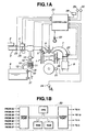
- Fig. 1A shows a system configuration of an internal combustion engine to which a first preferred embodiment of an apparatus for estimating a concentration of a vaporized fuel in an intake air according to the present invention is applicable.
- An intake air from an air cleaner 2 is sucked into a combustion chamber of each cylinder of the engine 1 mounted in a vehicle through an intake air passage 3 receiving a control of its quantity from a throttle valve 4 (so-called, an electronically controlled throttle valve).
- a throttle valve 4 so-called, an electronically controlled throttle valve
- An electromagnetic type fuel injection valve (injector) 5 is installed in a part of the intake air passage 3 near to an intake valve so as to inject a given quantity of fuel (gasoline) into each corresponding combustion chamber.
- Each fuel injection valve 5 has a solenoid portion which opens in response to a fuel injection pulse signal outputted in a suction stroke or a compression stroke of its corresponding cylinder in synchronization with an engine rotation from a controller 20 so that the given quantity of fuel pressurized under a predetermined pressure is injected.
- the injected fuel is diffused over each corresponding combustion chamber to form a homogeneous air mixture fuel in the case of the fuel injection at the suction stroke of each corresponding cylinder and is formed in a stratified air mixture fuel concentratedly around a spark plug 6 in the case of the fuel injection at the compression stroke of each corresponding cylinder.
- the spark plug 6 constituted by an ignition device is sparked to ignite and burn the air-fuel mixture in each combustion chamber so that the air-mixture fuel is combusted in a combustion condition as a, so-called, homogeneous charge combustion or stratified charge combustion.
- the combustion condition in the engine 1 is divided into three combustion conditions, in combination with an air-fuel mixture ratio control, a homogeneous stoichiometric air-fuel mixture ratio charge combustion; a homogeneous lean air-fuel mixture ratio combustion (air-fuel mixture ratio ranging from 20 to 30); and a stratified lean air-fuel mixture ratio combustion (air-fuel mixture ratio of approximately 40).
- An exhaust gas from the engine 1 is exhausted through an exhaust gas passage 7 and a catalytic converter 8 used to purify the exhaust gas and being interposed within the exhaust gas passage 7.
- a canister 10 constituting a vaporized fuel processor is installed in the engine 1 so as to process the vaporized fuel generated by a fuel tank 9.
- the canister 10 is filled with an adsorbent 11 such as an activated carbon within a sealed vessel, with a vaporized fuel introducing conduit 12 from the fuel tank 9 connected thereto.
- the vaporized fuel developed in the fuel tank 9 during a stop of the engine 1 is introduced into the canister 10 through the vaporized fuel introducing conduit 12 and is adsorbed onto the adsorbent 11 of the canistor 10.
- the canister 10 is formed with a fresh air introducing inlet 13 and a purge (gas) passage 14 is introduced from the canister 10.
- the purge passage 14 is connected to a downstream side (intake manifold) of the intake air passage 3 with respect to a purge control valve 15.
- the purge control valve 15 is open in response to a signal outputted under a predetermined engine driving condition of the engine 1 from the controller 20. Hence, if a purge enabling combustion is established with the engine 1 being started, the purge control valve 15 is open so that an intake air negative pressure of the engine 1 is acted upon the canistor 10.
- An air introduced from the fresh air introducing inlet 13 causes the vaporized fuel adsorbed onto the adsorbent 11 of the canister 10 to be desorbed from the adsorbent 11, the purge gas including the desorbed vaporized fuel being sucked into the downstream side of the intake air passage 3 with respect to the intake air passage 3 through the purge gas passage 14. Thereafter, the purge gas described above is combusted within each combustion chamber of the engine 1.
- the controller 20 includes: a microcomputer having a CPU (Central Processing Unit), a ROM (Read Only Memory); RAM (Random Access Memory), a common bus, an Input Port having an A/D converter and an Output Port having an D/A converter, as shown in Fig. 1B.
- a microcomputer having a CPU (Central Processing Unit), a ROM (Read Only Memory); RAM (Random Access Memory), a common bus, an Input Port having an A/D converter and an Output Port having an D/A converter, as shown in Fig. 1B.
- the controller 20 Upon receipt of input signals from various engine driving condition sensors, the controller 20 performs various arithmetic/logic operations on the basis of the input signals and controls operations over each fuel injection valve 5, each spark plug 6, and the purge control valve 15.
- crank angle sensors 21 and 22 detecting a crankshaft axis rotation or camshaft axis rotation of the engine 1.
- crank angle sensors 21 and 22 if the engine 1 has the number of cylinders of n, outputs to the controller 20 a reference pulse signal REF at a predetermined crank angular position (for example, 110° before an upper top dead center in the compression stroke of each cylinder) whenever a crank angular position of 720°/n is inputted and outputs to the controller 20 a unit pulse signal POS whenever the crank angular position of 1° or 2° is revolved.
- a reference pulse signal REF at a predetermined crank angular position (for example, 110° before an upper top dead center in the compression stroke of each cylinder) whenever a crank angular position of 720°/n is inputted and outputs to the controller 20 a unit pulse signal POS whenever the crank angular position of 1° or 2° is revolved.
- the CPU of the controller 20 can calculate an engine speed Ne from such as a period of the reference pulse signal REF.
- the other sensors include: an air-flow meter 23 located at the upstream side of the intake air passage 3 with respect to the throttle valve 4 for detecting an intake air quantity Qa; an acceleration sensor 24 for detecting a depression angle through which a driver has depressed (accelerator depression angle )ACC; a throttle sensor 25 for detecting an opening angle TVO of the throttle valve 4 (including an idle switch which is turned to ON when the throttle valve 4 is completely closed); an engine coolant temperature sensor 26 for detecting a coolant temperature Tw of the engine 1; an (normal type) oxygen concentration sensor (so-called, O 2 sensor) 27 for outputting a signal corresponding to a rich and lean state of an exhaust gas air-fuel mixture ratio in the exhaust gas passage 7 (according to an oxygen concentration in the exhaust gas); and a vehicle speed sensor 28 for detecting a vehicle speed VSP.
- an air-flow meter 23 located at the upstream side of the intake air passage 3 with respect to the throttle valve 4 for detecting an intake air quantity Qa
- an acceleration sensor 24 for
- the various sensors include: an air conditioner operation gas pressure sensor 29 for detecting an operation gas pressure of the air conditioner, namely, a discharging pressure of an air compressor in the air conditioner; an external air temperature sensor 30 for detecting an external (ambient) air temperature Ta external to the vehicle; a fuel temperature sensor for detecting a fuel temperature Tt within a fuel tank 9; and a pressure sensor 32 for detecting an air pressure Pt in the fuel tank 9.
- an air conditioner operation gas pressure sensor 29 for detecting an operation gas pressure of the air conditioner, namely, a discharging pressure of an air compressor in the air conditioner
- an external air temperature sensor 30 for detecting an external (ambient) air temperature Ta external to the vehicle
- a fuel temperature sensor for detecting a fuel temperature Tt within a fuel tank 9
- a pressure sensor 32 for detecting an air pressure Pt in the fuel tank 9.
- the microcomputer of the controller 20 commands the engine 1 to temporarily carry out a stoichiometric air-fuel mixture ratio charge combustion (homogeneous stoichiometric air-fuel mixture ratio charge combustion).
- the microcomputer of the engine 20 commands the engine 1 to be temporarily forced into a stoichiometric air-fuel mixture ratio combustion (homogeneous stoichiometric air-fuel mixture ratio combustion) whenever a predetermined interval of time has passed even during a lean air-fuel mixture ratio combustion condition (a homogeneous lean air-fuel mixture change combustion or a stratified lean air-fuel mixture ratio charge combustion).
- a stoichiometric air-fuel mixture ratio combustion homogeneous stoichiometric air-fuel mixture ratio combustion
- a concentration of the vaporized fuel in the intake air is estimated on the basis of a signal derived from the oxygen concentration (O 2 ) sensor 27.
- Figs. 2, 3, 4, 5, 6, 7, 8, and 9 respectively show flowcharts executed by the controller 20.
- Fig. 2 shows a routine to vary a time interval of operations which is executed in the first embodiment shown in.Fig. 1A whenever a predetermined period of time has passed.
- the CPU of the controller 20 reads a vehicle speed VSP detected by the vehicle speed sensor 28.
- the CPU of the controller 20 compares the vehicle speed VSP with a predetermined value (PRE) to determine whether the vehicle speed VSP is equal to or above the predetermined value.
- PRE predetermined value
- VSP ⁇ PRE (Yes) at the step S2, viz., the vehicle speed is relatively high, the routine goes to a step S3.
- the value of the relatively long time interval TL is, for example, 10 minutes.
- VSP ⁇ PRE relatively low vehicle speed
- the value of the relatively short time interval TS is, for example, five minutes (300 seconds).
- Fig. 3 shows a stoichiometric air-fuel mixture ratio force command determination routine executed in the first embodiment shown in Fig. 1A whenever the predetermined period of time has passed.
- the CPU of the controller 20 determines whether the present combustion condition falls in the lean combustion condition (homogeneous lean air-fuel mixture ratio charge combustion or stratified lean air-fuel mixture ratio charge combustion).
- the routine goes to a step S12.
- the CPU of the controller 20 refers to the count value of the timer TM which indicates a continuation time of the lean air-fuel mixture ratio combustion.
- the CPU of the controller 20 compares the timer TM with the operation interval INTEVT set by the routine of Fig. 3 to determine whether the value of the timer TM is equal to or larger than INTEVT (TM ⁇ INTEVT).
- step S14 the routine goes to a step S15 in which the CPU of the controller 20 issues a command to force the combustion condition of the engine 1 into the stoichiometric air-fuel mixture ratio charge combustion.
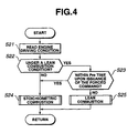
- Fig. 4 shows a combustion condition control routine which is executed in the first embodiment shown in Fig. 1A whenever the predetermined period of time has passed.
- the CPU of the controller 20 determines whether the present driving condition falls in a predetermined lean combustion condition in accordance with the driving condition of the engine 1.
- the routine goes to a step S23 in which it is within a predetermined time from a time at which the CPU of the controller 20 has issued the command to the engine 1 to be forced into the homogeneous stoichiometric air-fuel mixture ratio charge combustion.
- the routine goes to a step S24 in which the combustion condition of the engine 1 is in the homogeneous stoichiometric air-fuel mixture ratio combustion.
- the CPU of the controller 20 sets a target air-fuel mixture ratio of the air-fuel mixture so as to perform an air-fuel mixture ratio feedback control (closed loop control) and sets a fuel supply (injection) timing of a fuel at the suction stroke of each cylinder so that each cylinder performs the homogeneous stoichiometric air-fuel mixture ratio charge combustion.
- the CPU of the controller 20 sets the target air-fuel mixture ratio to a lean air-fuel mixture ratio so as to perform an open loop control and the injection timing of the fuel is set to each suction stroke or to each compression stroke so as to perform the homogeneous lean air-fuel mixture ratio charge combustion or the stratified lean air-fuel mixture ratio charge combustion.
- the CPU of the controller 20 determines whether the present combustion condition falls in the stoichiometric air-fuel mixture ratio combustion (during the feedback control of the air-fuel mixture ratio).
- the CPU of the controller 20 reads an output signal (output voltage) VO 2 from the oxygen concentration (O 2 ) sensor 27.
- the CPU of the controller compares a value of the output signal VO 2 with a predetermined slice level (SL) so as to determine a rich state or lean state of the exhaust gas air-fuel mixture ratio.
- the CPU of the controller 20 multiplies a basic fuel supply (injection) quantity by the air-fuel mixture ratio feedback correction coefficient ⁇ increased or decreased by the integration control when the fuel supply (injection) quantity Ti is calculated.
- the air-fuel mixture ratio can be controlled so as to match with a target air-fuel mixture ratio, viz., a stoichiometric air-fuel mixture ratio.
- the CPU of the controller 20 calculates an average value ⁇ mean of the air-fuel mixture ratio feedback correction coefficient ⁇ .
- the magnitude of the purge concentration can be determined according to the thus calculated purge concentration corresponding value ⁇ .
- the corrected fuel supply (injection) quantity (Ti'lean) is calculated as follows:
- the return to the lean air-fuel mixture combustion may be delayed so as to continue the homogeneous stoichiometric air-fuel mixture ratio charge combustion for a while.
- the present combustion may be transferred into the lean air-fuel mixture ratio combustion (corresponding to one of the stratified or homogeneous charge combustion).
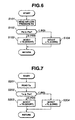
- Fig. 6 shows another operation time interval variable routine in place of the operation time interval variable routine shown in Fig. 2 as a second preferred embodiment according to the present invention.
- the CPU of the controller 20 reads the air-conditioner operation gas pressure Pd detected by the air-conditioner operation gas pressure sensor 29.
- the CPU of the controller 20 compares the air-conditioner operation gas pressure Pd with a predetermined value thereof Pre so as to determine whether the air-conditioner operation gas pressure Pd is equal to or above the predetermined value (Pre).
- the air-conditioner operation gas pressure Pd becomes higher, the external air temperature can be deemed to be high and the development quantity of the vaporized fuel is increased.
- the operation time interval INTEVT can be varied depending on an operation condition of the air conditioner (the air-conditioner operation gas Pd or the air conditioner power switch).
- Fig. 7 shows a still another operation time interval variable routine in place of the operation time interval routine shown in Fig. 2 as a third preferred embodiment according to the present invention.
- the CPU of the controller 20 reads the external air temperature Ta detected by the external air temperature sensor 30.
- the CPU of the controller 20 compares the external air temperature Ta with a predetermined value thereof (Pre) so as to determine whether the detected external air temperature Ta is equal to or above the predetermined value (Pre).
- the concentration of the vaporized fuel can accurately be estimated.
- Fig. 8 shows a still another operation time interval variable routine in place of the routine shown in Fig. 2 as a fourth preferred embodiment according to the present invention.
- the CPU of the controller 20 reads an intake fuel temperature sensor Tt detected by the fuel temperature sensor 31 installed in the fuel tank 9.
- the CPU of the controller 20 compares the in-tank fuel temperature Tt with a predetermined value thereof.
- Tt ⁇ Pre namely, the in-tank fuel temperature Tt is so high as to be equal to or above the predetermined value
- the CPU of the controller 20 determines that the development speed of the vaporized fuel is high and the routine goes to a step S403.
- the concentration of the vaporized fuel based on the in-tank fuel temperature Tt can be estimated.
- Fig. 9 shows a still further another operation time interval variable routine in place of the routine shown in Fig. 2 as a fifth preferred embodiment according to the present invention.
- the CPU of the controller 20 reads the in-take air pressure Pt detected by the in-tank pressure sensor 32.
- the CPU of the controller 20 compares the in-tank air pressure Pt with a predetermined value (Pre) so as to determine whether the intake air pressure Pt is equal to or above the predetermined value (Pre).
- the in-tank pressure Pt is a measurement result of the variation in the development speed of the vaporized fuel, the concentration of the vaporized fuel can be more accurately be estimated.
- each command generator, each estimator, each determinator, a fuel supply quantity corrector, and a air-fuel mixture ratio feedback controller described in claims are incorporated in terms of software into the controller 20 as described above.
Landscapes
- Engineering & Computer Science (AREA)
- Chemical & Material Sciences (AREA)
- Combustion & Propulsion (AREA)
- Mechanical Engineering (AREA)
- General Engineering & Computer Science (AREA)
- Electrical Control Of Air Or Fuel Supplied To Internal-Combustion Engine (AREA)
- Supplying Secondary Fuel Or The Like To Fuel, Air Or Fuel-Air Mixtures (AREA)
- Combined Controls Of Internal Combustion Engines (AREA)
Claims (15)
- Moteur à combustion interne comprenant:a) un passage d'air d'admission (3);b) un réservoir de carburant (9);c) un dispositif de commande de carburant vaporisé, disposé entre le réservoir de carburant (9) et le passage d'air d'admission (3) pour absorber le carburant vaporisé du réservoir de carburant (9) et pour purger le carburant vaporisé de celui-ci dans le passage d'air d'admission (3);d) un capteur de concentration d'oxygène (27), installé dans un passage des gaz d'échappement (7) pour détecter un rapport de mélange air-combustible en accord avec une concentration d'oxygène dans les gaz d'échappement;e) un générateur de commande pour produire et émettre une commande au moteur (1) pour transférer de force un état de combustion du moteur (1) en une combustion stoéchiométrique du rapport air-combustible; etf) un appareil d'estimation pour estimer la concentration du carburant vaporisé purgé dans le passage d'air d'admission (3) pendant la combustion du rapport de mélange air-combustible stoéchiométrique, caractérisé en ce queg) le dispositif de commande de carburant vaporisé comporte un moyen pour corriger la quantité d'amenée du carburant sur la base de la concentration de purge après que l'état de combustion a été transféré en combustion du rapport de mélange air-combustible apauvri.
- Moteur à combustion interne selon la revendication 1, caractérisé en ce que le dispositif d'estimation comprend en outre un autre dispositif d'estimation pour estimer une quantité de carburant vaporisé dans le réservoir de carburant (9), et le dispositif d'estimation estime la concentration du carburant vaporisé purgé dans le passage d'air d'admission (3) à partir de la quantité estimée de carburant vaporisé dans le réservoir de carburant (9), et le générateur de commande émet la commande au moteur (1) pour transférer de force l'état de combustion en combustion au rapport de mélange air-combustible stoéchiométrique, à chaque fois qu'un intervalle de temps prédéterminé s'est écoulé, pour l'estimation du carburant vaporisé dans le réservoir de carburant (9) par l'autre dispositif d'estimation.
- Moteur à combustion interne selon la revendication 2, caractérisé en ce que l'autre dispositif d'estimation comprend un capteur (28) de la vitesse de véhicule pour détecter une vitesse d'un véhicule dans lequel le moteur (1) est installé, qui comprend en outre un premier organe de détermination pour déterminer si la vitesse détectée du véhicule est égale ou supérieure à une valeur de vitesse de véhicule prédéterminée, et où l'intervalle de temps prédéterminé est réglé pour être relativement court lorsque le premier organe de détermination détermine que la vitesse du véhicule est égale ou supérieure à la valeur de vitesse de véhicule prédéterminée.
- Moteur à combustion interne selon la revendication 2 ou 3, caractérisé en ce que l'autre dispositif d'estimation comprend un capteur de fonctionnement d'un dispositif de climatisation (29) pour détecter si un dispositif de climatisation d'un véhicule dans lequel le dispositif de climatisation est installé, fonctionne, et l'intervalle de temps prédéterminé est réglé pour être relativement court lorsque le capteur de fonctionnement du dispositif de climatisation détecte que le dispositif de climatisation est en fonctionnement.
- Moteur à combustion interne selon au moins l'une des revendications 2 à 4, caractérisé en ce que l'autre dispositif d'estimation comprend un capteur de température d'air externe (30) pour détecter une température d'air à l'extérieur d'un véhicule dans lequel le moteur (1) est installé, qui comprend en outre un deuxième organe de détermination pour déterminer si la température d'air détectée est égale ou supérieure à une valeur de température d'air prédéterminée, et où l'intervalle de temps prédéterminé est réglé pour être relativement court lorsque le deuxième organe de détermination détermine que la température d'air détectée est égale ou supérieure à la valeur de température d'air prédéterminée.
- Moteur à combustion interne selon au moins l'une des revendications 2 à 5, caractérisé en ce que l'autre dispositif d'estimation comprend un capteur de la température du carburant pour détecter la température du carburant dans le réservoir de carburant (9), qui comprend en outre un troisième organe de détermination pour déterminer si la température détectée du carburant dans le réservoir de carburant (9) est égale ou supérieure à une valeur de température prédéterminée, et où l'intervalle de temps prédéterminée est réglé pour être relativement court lorsque le troisième organe de détermination détermine que la température détectée du carburant dans le réservoir de carburant (9) est égale ou supérieure à la valeur de température prédéterminée.
- Moteur à combustion interne selon au moins l'une des revendications 2 à 6, caractérisé en ce que l'autre dispositif d'estimation comprend un capteur de température (32) pour détecter une pression d'air dans le réservoir de carburant (9), qui comprend en outre un quatrième organe de détermination pour déterminer si la pression d'air détectée dans le réservoir de carburant (9) est égale ou au-dessus d'une valeur de pression d'air prédéterminée, et où l'intervalle de temps prédéterminé est réglé pour être relativement court lorsque le quatrième organe de détermination détermine que la pression d'air détectée dans le réservoir de carburant (9) est égale ou supérieure à la valeur de pression d'air prédéterminée.
- Moteur à combustion interne selon au moins l'une des revendications 1 à 7, caractérisé en ce que le dispositif d'estimation estime la concentration du carburant vaporisé purgé dans le passage d'air d'admission (3) sur la base d'un coefficient de correction de réinjection du rapport de mélange air-combustible ( α) pendant la combustion au rapport de mélange air-combustible stoéchiométrique.
- Moteur à combustion interne selon la revendication 8, caractérisé en outre en ce qu'il comprend un dispositif de commande de réinjecton pour exécuter une commande de réinjection sur le rapport de mélange air-combustible de manière à amener le rapport de mélange air-combustible détecté par le capteur de la concentration d'oxygène (27) à approcher le rapport de mélange air-combustible stoéchiométrique pendant la combustion au rapport de mélange air-combustible stoéchiométrique, et où le dispositif d'estimation estime la concentration du carburant vaporisé purgé dans le passage d'air d'admission (3) sur la base d'un coefficient de correction de réinjection du rapport de mélange air-combustible ( α) obtenu à partir d'un signal de sortie du capteur de concentration d'oxygène (27) par le dispositif de commande de réinjection.
- Moteur à combustion interne selon la revendication 9, caractérisé en ce que le dispositif d'estimation estime la concentration du carburant vaporisé purgé dans le passage d'air d'admission (3) à partir d'un écart ( Δα) d'une valeur moyenne (α moyenne) entre la valeur maximale ( α max) et la valeur minimale ( α min) du coefficient de correction de réinjection du rapport de mélange air-combustible ( α) à partir d'une valeur de référence de celui-ci.
- Moteur à combustion interne selon la revendication 9, caractérisé en ce que le dispositif d'estimation estime la concentration du carburant vaporisé purgé dans le passage d'air d'admission (3) du moteur à partir d'un écart ( Δα) d'une valeur moyenne ( α moyenne) entre la valeur maximale (α max) et la valeur minimale ( α min) du coefficient de correction de réinjection du rapport de mélange air-combustible (α) à partir du coefficient ( α0) de correction de réinjection du rapport de mélange air-combustible en l'absence d'une purge du carburant vaporisé dans le passage d'air d'admission (3).
- Moteur à combustion interne selon au moins l'une des revendications 1 à 11, caractérisé en ce qu'il comprend en outre un générateur de commande d'état de combustion appauvri pour générer et émettre une commande au moteur (1) pour transférer l'état de combustion en combustion au rapport de mélange air-combustible appauvri pendant un état d'entraínement prédéterminé du moteur, et un organe de correction de la quantité d'amenée de carburant pour corriger une quantité d'amenée de carburant pour le moteur (1) par un facteur déterminé sur la base de la quantité estimée du carburant vaporisé purgé dans le passage d'air d'admission (3) pendant la combustion au rapport de mélange air-combustible appauvri.
- Procédé, applicable à un moteur à combustion interne, comprenant les étapes consistant à:a) prévoir un passage d'air d'admission (3) ;b) prévoir un réservoir de carburant (9) ;c) interposer un dispositif de traitement de carburant vaporisé entre le réservoir de carburant (9) et le passage d'air d'admission (3);d) adsorber un carburant vaporisé du réservoir de carburant (9) au dispositif de traitement de carburant vaporisé;e) purger le carburant vaporisé de celui-ci dans le passage d'air d'admission (3);f) installer un capteur (27) de la concentration d'oxygène dans un passage des gaz d'échappement (7);g) produire et émettre une commande au moteur (1) de manière à transférer de force un état de combustion du moteur (1) en une combustion au rapport de mélange air-combustible stoéchiométrique;h) détecter un rapport de mélange air-combustible par le capteur (27) de la concentration d'oxygène en accord avec une concentration d'oxygène dans les gaz d'échappement; eti) estimer une concentration du carburant vaporisé purgé dans le passage d'air d'admission (3) pendant la combustion au rapport de mélange air-combustible stoéchiométrique, etj) corriger la quantité d'amenée de carburant sur la base de la concentration de purge après que l'état de combustion a été transféré en combustion au rapport de mélange air-combustible appauvri.
- Procédé, applicable à un moteur à combustion interne, selon la revendication 13, caractérisé en ce qu'il comprend en outre l'étape consistant à:k) estimer une quantité de carburant vaporisé dans le réservoir de carburant (9), et où l'étape d'estimation de i) estime la concentration du carburant vaporisé purgé dans le passage d'air d'admission (3) à partir de la quantité estimée de carburant vaporisé dans le réservoir de carburant à l'étape k), et le générateur de commande émet la commande au moteur (1) de transférer de force l'état de combustion en combustion au rapport de mélange air-combustible stoéchiométrique à chaque fois qu'un intervalle de temps prédéterminé s'est écoulé, l'intervalle de temps prédéterminé étant modifié sur la base de la quantité estimée de carburant vaporisé dans le réservoir de carburant (9) à l'étape k).
- Procédé, applicable à un moteur à combustion interne, selon la revendication 13, caractérisé en ce qu'à l'étape d'estimation de i), la concentration du carburant vaporisé purgé dans le passage d'air d'admission (3) du moteur (1) est estimée sur la base d'un résultat de détection par le capteur (27) de la concentration de l'oxygène à l'étape de h) .
Applications Claiming Priority (3)
| Application Number | Priority Date | Filing Date | Title |
|---|---|---|---|
| JP21437997 | 1997-08-08 | ||
| JP214379/97 | 1997-08-08 | ||
| JP21437997A JP3496468B2 (ja) | 1997-08-08 | 1997-08-08 | 内燃機関の蒸発燃料濃度判定装置 |
Publications (3)
| Publication Number | Publication Date |
|---|---|
| EP0896143A2 EP0896143A2 (fr) | 1999-02-10 |
| EP0896143A3 EP0896143A3 (fr) | 2000-09-13 |
| EP0896143B1 true EP0896143B1 (fr) | 2004-05-12 |
Family
ID=16654819
Family Applications (1)
| Application Number | Title | Priority Date | Filing Date |
|---|---|---|---|
| EP98114576A Expired - Lifetime EP0896143B1 (fr) | 1997-08-08 | 1998-08-03 | Dispositif et méthode pour l'estimation de la concentration des vapeurs de carburant purgées dans un conduit d'admission de moteur à combustion interne |
Country Status (5)
| Country | Link |
|---|---|
| US (1) | US6079397A (fr) |
| EP (1) | EP0896143B1 (fr) |
| JP (1) | JP3496468B2 (fr) |
| KR (1) | KR100288519B1 (fr) |
| DE (1) | DE69823754T2 (fr) |
Families Citing this family (19)
| Publication number | Priority date | Publication date | Assignee | Title |
|---|---|---|---|---|
| KR100336549B1 (ko) * | 1996-12-16 | 2002-10-25 | 도요다 지도샤 가부시끼가이샤 | 희박연소내연기관의증발연료공급제어장치 |
| DE19719760A1 (de) * | 1997-05-10 | 1998-11-12 | Bosch Gmbh Robert | System zum Betreiben einer direkteinspritzenden Brennkraftmaschine insbesondere eines Kraftfahrzeugs |
| US6257209B1 (en) | 1998-03-18 | 2001-07-10 | Toyota Jidosha Kabushiki Kaisha | Evaporative fuel processing apparatus for lean-burn internal combustion engine |
| JP3861446B2 (ja) | 1998-03-30 | 2006-12-20 | トヨタ自動車株式会社 | 希薄燃焼内燃機関の蒸発燃料濃度検出装置及びその応用装置 |
| JP3753166B2 (ja) * | 1998-08-27 | 2006-03-08 | 株式会社日立製作所 | 内燃機関の蒸発燃料処理装置 |
| JP3829035B2 (ja) * | 1999-11-30 | 2006-10-04 | 株式会社日立製作所 | エンジンの燃料圧力制御装置 |
| JP3637825B2 (ja) | 1999-12-15 | 2005-04-13 | 日産自動車株式会社 | 可変動弁エンジンの制御装置 |
| US6524884B1 (en) * | 2001-08-22 | 2003-02-25 | Korea Electronics And Telecommunications Research Institute | Method for fabricating an organic electroluminescene device having organic field effect transistor and organic eloectroluminescence diode |
| US6523531B1 (en) * | 2001-12-03 | 2003-02-25 | Ford Global Technologies, Inc. | Feed forward method for canister purge compensation within engine air/fuel ratio control systems having fuel vapor recovery |
| DE10244391A1 (de) * | 2002-09-24 | 2004-04-01 | Volkswagen Ag | Verfahren zum Betreiben einer direkteinspritzenden Brennkraftmaschine |
| JP2004360553A (ja) | 2003-06-04 | 2004-12-24 | Suzuki Motor Corp | 内燃機関の蒸発燃料制御装置 |
| JP4370936B2 (ja) * | 2004-02-24 | 2009-11-25 | トヨタ自動車株式会社 | 内燃機関の燃料噴射制御装置 |
| JP2005248895A (ja) * | 2004-03-05 | 2005-09-15 | Toyota Motor Corp | 内燃機関の制御装置 |
| EP1781917B1 (fr) * | 2004-06-15 | 2012-11-28 | Toyota Jidosha Kabushiki Kaisha | Dispositif de commande pour un systeme de vidange d'un systeme de systeme a double injecteurs-pompes destine a un moteur thermique |
| DE602007000440D1 (de) * | 2007-02-08 | 2009-02-12 | Delphi Tech Inc | Kraftstoffdampf-Tankentlüftungssystem für einen Fahrzeugkraftstofftank |
| DE102009035845A1 (de) * | 2009-07-31 | 2011-02-03 | Dr. Ing. H.C. F. Porsche Aktiengesellschaft | Verfahren zum Betreiben eines Kraftstoffverdunstungs-Rückhaltesystems |
| DE102011086221A1 (de) * | 2011-11-11 | 2013-05-16 | Robert Bosch Gmbh | Optimierung einer Tankentlüftung eines Kraftstofftanks |
| US8838363B2 (en) * | 2012-01-24 | 2014-09-16 | Ford Global Technologies, Llc | Method for injecting fuel |
| US11085382B2 (en) * | 2018-03-02 | 2021-08-10 | Ford Global Technologies, Llc | Evaporative emission control system and method |
Family Cites Families (11)
| Publication number | Priority date | Publication date | Assignee | Title |
|---|---|---|---|---|
| DE4319772A1 (de) * | 1993-06-15 | 1994-12-22 | Bosch Gmbh Robert | Verfahren und Vorrichtung zum Steuern einer Tankentlüftungsanlage |
| JPH0742588A (ja) | 1993-08-03 | 1995-02-10 | Mitsubishi Motors Corp | 燃料蒸発ガス処理システム |
| JP2867912B2 (ja) * | 1994-03-14 | 1999-03-10 | トヨタ自動車株式会社 | 内燃機関の蒸発燃料処理装置 |
| JP3689126B2 (ja) * | 1994-03-18 | 2005-08-31 | 本田技研工業株式会社 | 内燃機関の蒸発燃料制御装置 |
| US5553595A (en) * | 1994-03-30 | 1996-09-10 | Mazda Motor Corporation | Fuel system with fuel vapor estimating feature |
| WO1996018814A1 (fr) * | 1994-12-15 | 1996-06-20 | Mitsubishi Jidosha Kogyo Kabushiki Kaisha | Systeme de controle de l'evaporation de carburant |
| JP3438386B2 (ja) * | 1995-03-16 | 2003-08-18 | 日産自動車株式会社 | エンジンの燃料蒸気処理装置 |
| JP3511722B2 (ja) * | 1995-03-20 | 2004-03-29 | 三菱電機株式会社 | 内燃機関の空燃比制御装置 |
| JPH09202131A (ja) * | 1996-01-24 | 1997-08-05 | Fuji Heavy Ind Ltd | フューエル臭の車室内侵入防止装置 |
| JPH09214379A (ja) | 1996-02-05 | 1997-08-15 | Alpine Electron Inc | 多重放送受信機 |
| JP3287228B2 (ja) * | 1996-08-09 | 2002-06-04 | トヨタ自動車株式会社 | 内燃機関の蒸発燃料処理装置 |
-
1997
- 1997-08-08 JP JP21437997A patent/JP3496468B2/ja not_active Expired - Fee Related
-
1998
- 1998-08-03 DE DE69823754T patent/DE69823754T2/de not_active Expired - Fee Related
- 1998-08-03 EP EP98114576A patent/EP0896143B1/fr not_active Expired - Lifetime
- 1998-08-07 US US09/130,485 patent/US6079397A/en not_active Expired - Fee Related
- 1998-08-08 KR KR1019980032311A patent/KR100288519B1/ko not_active Expired - Fee Related
Also Published As
| Publication number | Publication date |
|---|---|
| DE69823754T2 (de) | 2004-10-07 |
| KR100288519B1 (ko) | 2001-06-01 |
| KR19990023479A (ko) | 1999-03-25 |
| DE69823754D1 (de) | 2004-06-17 |
| JPH1162728A (ja) | 1999-03-05 |
| EP0896143A2 (fr) | 1999-02-10 |
| US6079397A (en) | 2000-06-27 |
| JP3496468B2 (ja) | 2004-02-09 |
| EP0896143A3 (fr) | 2000-09-13 |
Similar Documents
| Publication | Publication Date | Title |
|---|---|---|
| US6079397A (en) | Apparatus and method for estimating concentration of vaporized fuel purged into intake air passage of internal combustion engine | |
| KR0130006B1 (ko) | 내연엔진의 아이들회전수제어방법 | |
| EP0889221B1 (fr) | Système de commande pour un moteur à combustion interne | |
| US5727528A (en) | Control apparatus and control method of internal combustion engine | |
| US5699778A (en) | Fuel evaporative emission suppressing apparatus | |
| KR100336549B1 (ko) | 희박연소내연기관의증발연료공급제어장치 | |
| US6739310B2 (en) | Method and electronic control device for diagnosing the mixture production in an internal combustion engine | |
| US5605132A (en) | Control method and controller for engine | |
| US6039032A (en) | Air-fuel ratio controller for an internal combustion engine | |
| EP0869268B1 (fr) | Commande de rapport air-carburant pour moteur à combustion | |
| US6550465B2 (en) | Cylinder air/fuel ratio estimation system of internal combustion engine | |
| KR100306186B1 (ko) | 내연기관의가솔린증기퍼어징제어장치및가솔린증기퍼어징방법 | |
| US6412477B2 (en) | Method and apparatus for controlling fuel vapor, method and apparatus for diagnosing fuel vapor control apparatus and method and apparatus for controlling air-fuel ratio | |
| JP4778401B2 (ja) | 内燃機関の制御装置 | |
| JP3337410B2 (ja) | 内燃機関の蒸発燃料処理装置 | |
| JPH08200166A (ja) | 空燃比制御装置 | |
| JP3560156B2 (ja) | 内燃機関の蒸発燃料制御装置 | |
| US6273063B1 (en) | Apparatus and method for controlling idle rotation speed of an internal combustion engine | |
| JPH1018890A (ja) | 内燃機関の電子制御燃料噴射装置 | |
| JP3564945B2 (ja) | 内燃機関の燃料供給制御装置 | |
| JP2002013437A (ja) | 筒内噴射式内燃機関の制御装置 | |
| JPH1144237A (ja) | 内燃機関の空燃比制御装置 | |
| JP3349398B2 (ja) | 内燃機関の蒸発燃料処理装置 | |
| JP3337411B2 (ja) | 内燃機関の蒸発燃料処理装置 | |
| JPH07243339A (ja) | 内燃機関の制御装置 |
Legal Events
| Date | Code | Title | Description |
|---|---|---|---|
| PUAI | Public reference made under article 153(3) epc to a published international application that has entered the european phase |
Free format text: ORIGINAL CODE: 0009012 |
|
| 17P | Request for examination filed |
Effective date: 19980803 |
|
| AK | Designated contracting states |
Kind code of ref document: A2 Designated state(s): DE FR GB |
|
| AX | Request for extension of the european patent |
Free format text: AL;LT;LV;MK;RO;SI |
|
| PUAL | Search report despatched |
Free format text: ORIGINAL CODE: 0009013 |
|
| AK | Designated contracting states |
Kind code of ref document: A3 Designated state(s): AT BE CH CY DE DK ES FI FR GB GR IE IT LI LU MC NL PT SE |
|
| AX | Request for extension of the european patent |
Free format text: AL;LT;LV;MK;RO;SI |
|
| AKX | Designation fees paid |
Free format text: DE FR GB |
|
| 17Q | First examination report despatched |
Effective date: 20030620 |
|
| GRAP | Despatch of communication of intention to grant a patent |
Free format text: ORIGINAL CODE: EPIDOSNIGR1 |
|
| GRAS | Grant fee paid |
Free format text: ORIGINAL CODE: EPIDOSNIGR3 |
|
| GRAA | (expected) grant |
Free format text: ORIGINAL CODE: 0009210 |
|
| AK | Designated contracting states |
Kind code of ref document: B1 Designated state(s): DE FR GB |
|
| REG | Reference to a national code |
Ref country code: GB Ref legal event code: FG4D |
|
| REF | Corresponds to: |
Ref document number: 69823754 Country of ref document: DE Date of ref document: 20040617 Kind code of ref document: P |
|
| ET | Fr: translation filed | ||
| PLBE | No opposition filed within time limit |
Free format text: ORIGINAL CODE: 0009261 |
|
| STAA | Information on the status of an ep patent application or granted ep patent |
Free format text: STATUS: NO OPPOSITION FILED WITHIN TIME LIMIT |
|
| 26N | No opposition filed |
Effective date: 20050215 |
|
| REG | Reference to a national code |
Ref country code: GB Ref legal event code: 746 Effective date: 20070604 |
|
| PGFP | Annual fee paid to national office [announced via postgrant information from national office to epo] |
Ref country code: DE Payment date: 20080814 Year of fee payment: 11 |
|
| PGFP | Annual fee paid to national office [announced via postgrant information from national office to epo] |
Ref country code: FR Payment date: 20080818 Year of fee payment: 11 |
|
| PGFP | Annual fee paid to national office [announced via postgrant information from national office to epo] |
Ref country code: GB Payment date: 20080813 Year of fee payment: 11 |
|
| GBPC | Gb: european patent ceased through non-payment of renewal fee |
Effective date: 20090803 |
|
| REG | Reference to a national code |
Ref country code: FR Ref legal event code: ST Effective date: 20100430 |
|
| PG25 | Lapsed in a contracting state [announced via postgrant information from national office to epo] |
Ref country code: FR Free format text: LAPSE BECAUSE OF NON-PAYMENT OF DUE FEES Effective date: 20090831 Ref country code: DE Free format text: LAPSE BECAUSE OF NON-PAYMENT OF DUE FEES Effective date: 20100302 |
|
| PG25 | Lapsed in a contracting state [announced via postgrant information from national office to epo] |
Ref country code: GB Free format text: LAPSE BECAUSE OF NON-PAYMENT OF DUE FEES Effective date: 20090803 |