EP0896211A2 - Dispositif et procédé de détection de fuite - Google Patents
Dispositif et procédé de détection de fuite Download PDFInfo
- Publication number
- EP0896211A2 EP0896211A2 EP98306180A EP98306180A EP0896211A2 EP 0896211 A2 EP0896211 A2 EP 0896211A2 EP 98306180 A EP98306180 A EP 98306180A EP 98306180 A EP98306180 A EP 98306180A EP 0896211 A2 EP0896211 A2 EP 0896211A2
- Authority
- EP
- European Patent Office
- Prior art keywords
- fluid
- electrode
- bladder
- grounding electrode
- leak
- Prior art date
- Legal status (The legal status is an assumption and is not a legal conclusion. Google has not performed a legal analysis and makes no representation as to the accuracy of the status listed.)
- Granted
Links
- 238000000034 method Methods 0.000 title claims description 30
- 238000001514 detection method Methods 0.000 title description 6
- 239000012530 fluid Substances 0.000 claims abstract description 83
- 238000004891 communication Methods 0.000 claims abstract description 3
- 230000008859 change Effects 0.000 claims description 7
- 239000011248 coating agent Substances 0.000 claims description 6
- 238000000576 coating method Methods 0.000 claims description 6
- 230000000007 visual effect Effects 0.000 claims description 3
- 230000004044 response Effects 0.000 claims description 2
- 210000004291 uterus Anatomy 0.000 description 5
- 238000011282 treatment Methods 0.000 description 3
- 210000004696 endometrium Anatomy 0.000 description 2
- 238000012544 monitoring process Methods 0.000 description 2
- 210000000056 organ Anatomy 0.000 description 2
- 238000007669 thermal treatment Methods 0.000 description 2
- 238000011179 visual inspection Methods 0.000 description 2
- 241000282412 Homo Species 0.000 description 1
- 241001465754 Metazoa Species 0.000 description 1
- FAPWRFPIFSIZLT-UHFFFAOYSA-M Sodium chloride Chemical compound [Na+].[Cl-] FAPWRFPIFSIZLT-UHFFFAOYSA-M 0.000 description 1
- 230000006978 adaptation Effects 0.000 description 1
- 230000003466 anti-cipated effect Effects 0.000 description 1
- 230000015271 coagulation Effects 0.000 description 1
- 238000005345 coagulation Methods 0.000 description 1
- 230000000694 effects Effects 0.000 description 1
- 239000013013 elastic material Substances 0.000 description 1
- 238000002674 endoscopic surgery Methods 0.000 description 1
- 239000012212 insulator Substances 0.000 description 1
- 239000000463 material Substances 0.000 description 1
- 238000012986 modification Methods 0.000 description 1
- 230000004048 modification Effects 0.000 description 1
- 239000012811 non-conductive material Substances 0.000 description 1
- 230000035515 penetration Effects 0.000 description 1
- 230000008569 process Effects 0.000 description 1
- 238000001356 surgical procedure Methods 0.000 description 1
- 230000000451 tissue damage Effects 0.000 description 1
- 231100000827 tissue damage Toxicity 0.000 description 1
- 231100000331 toxic Toxicity 0.000 description 1
- 230000002588 toxic effect Effects 0.000 description 1
- 210000001215 vagina Anatomy 0.000 description 1
Images




Classifications
-
- G—PHYSICS
- G01—MEASURING; TESTING
- G01M—TESTING STATIC OR DYNAMIC BALANCE OF MACHINES OR STRUCTURES; TESTING OF STRUCTURES OR APPARATUS, NOT OTHERWISE PROVIDED FOR
- G01M3/00—Investigating fluid-tightness of structures
- G01M3/02—Investigating fluid-tightness of structures by using fluid or vacuum
- G01M3/04—Investigating fluid-tightness of structures by using fluid or vacuum by detecting the presence of fluid at the leakage point
- G01M3/16—Investigating fluid-tightness of structures by using fluid or vacuum by detecting the presence of fluid at the leakage point using electric detection means
- G01M3/18—Investigating fluid-tightness of structures by using fluid or vacuum by detecting the presence of fluid at the leakage point using electric detection means for pipes, cables or tubes; for pipe joints or seals; for valves; for welds; for containers, e.g. radiators
- G01M3/186—Investigating fluid-tightness of structures by using fluid or vacuum by detecting the presence of fluid at the leakage point using electric detection means for pipes, cables or tubes; for pipe joints or seals; for valves; for welds; for containers, e.g. radiators for containers, e.g. radiators
- G01M3/187—Investigating fluid-tightness of structures by using fluid or vacuum by detecting the presence of fluid at the leakage point using electric detection means for pipes, cables or tubes; for pipe joints or seals; for valves; for welds; for containers, e.g. radiators for containers, e.g. radiators for flexible or elastic containers
Definitions
- the invention relates to a device for detecting leaks in a fluid-filled container. More particularly, the present invention relates to an apparatus and method for detecting leaks in an expandable device filled with fluid, such as a fluid-filled balloon, which is used to treat a patient's body tissue during medical procedures.
- fluid such as a fluid-filled balloon
- Fluid-filled balloons have been used in various medical procedures. For example, surgical balloons are sometimes used in endoscopic surgeries to create working space within a human body.
- Other medical balloons include thermal treatment balloons which are inflated within a body cavity, such as a cavity defined by a human organ, and filled with a heated fluid to impart thermal energy to the organ.
- thermal energy with fluid-filled balloons has been of particular use in treating tissue in body cavities of animals, including humans.
- balloons filled with heated fluid have been used to effect coagulation and/or cauterization of a uterine endometrium.
- the distensible bladder is inflated to a predetermined pressure with a fluid so that the distensible bladder is in contact with substantially all of the tissue lining for which treatment is desired.
- the fluid is heated to a temperature sufficient to coagulate and/or ablate the tissue lining.
- the temperature and pressure of the fluid is controlled by means connected to the distensible bladder.
- a concern in various medical procedures utilizing fluid-filled balloons is the potential for leaks in the balloon.
- the fluids used to inflate medical balloons may in some cases cause discomfort to the patient if allowed to leak from the balloon directly into the patient's body. Some fluids may even be toxic to the human body. Accordingly, it is often desirable to rapidly and accurately detect leaks in fluid-filled balloons.
- Rapid detection of leaks can allow the surgeon or other user to rapidly deflate and remove a leaking balloon, thereby minimizing the amount of fluid leaking into the patient's body.
- Another method of detecting leaks during a procedure involves monitoring the internal pressure of the balloon to detect drops in internal pressure, which are indicative of a leak. Some pressure drops, however, may not be of sufficient size to trigger a leak detection alarm, particularly for very slow leaks. Detecting pressure drops may be difficult in procedures during which fluid from inside the balloon is pumped out and continuously replaced with "fresh" fluid from outside the balloon. The constant inflow and outflow of fluid can create pressure variations that may make pressure-sensitive leak detection systems ineffective.
- the present invention provides a method and apparatus for detecting fluid leaks in a fluid-filled bladder used to treat a patient's tissue, including surgical procedures, thermal treatment, and related procedures using fluid-filled devices.
- the apparatus comprises an expandable device defining a fluid reservoir therein for holding a conductive fluid, a supply conduit in fluid communication with the fluid reservoir for delivering the conductive fluid into the fluid reservoir, a first internal electrode in electrical contact with the fluid reservoir, a second grounding electrode positioned outside the expandable device, a power supply for generating a voltage between the first electrode and the grounding electrode, and a detector for detecting variations in the electrical current passing between the first electrode and the grounding electrode.
- the detector generates a leak signal in response to a change in the electrical current passing between the first electrode and the grounding electrode, and a leak alarm is activated to warn a user of a leak in the fluid reservoir.
- the alarm may be a visual or audio alarm, or a combination of video and audio elements.
- the alarm may indicate the magnitude of the leak.
- the internal electrode may comprise a conductive inner coating of the bladder.
- the grounding electrode may comprise a conductive outer coating of the bladder.
- the grounding electrode may alternatively be positioned on the outside of the device, or may be a separate element placed against the outside surface of the patient's body.
- the bladder is generally non-conductive, and little or no current passes from the internal electrode to the grounding electrode in the absence of a leak.
- the presence of any current between the internal electrode and the grounding electrode may be used to indicate a leak.
- the bladder- is conductive, and current may pass from the internal electrode to the grounding electrode even without the presence of a fluid leak in the balloon. Where a leak develops, the leaking fluid will alter the current flow between the internal and grounding electrode.
- the alarm may be activated by any current flow between the internal electrode and the grounding electrode. Alternately, the alarm may be activated when there is a substantial change in the current flow between the internal electrode and the grounding electrode.
- the power supply may provide and alternating or direct current source.
- the power supply may provide radio frequency power between the internal and grounding electrodes.
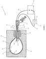
- FIGURE 1 is a side view, in partial cross section, of an apparatus according to one embodiment of the present invention, including a treatment catheter having a bladder.
- FIG. 1a is a side view, in partial cross-section, of an apapratus according to FIG. 1, wherein a leak is present in the bladder.
- FIG. 2 is a side view, in partial section, of an apparatus according to another embodiment of the invention.
- FIG. 3 is a side view, in partial cross section, of an apparatus according to a further embodiment of the invention.
- FIG. 4 shows an alarm according to one embodiment of the invention.
- FIG. 5 is a chart showing variations in leak current over time.
- FIG. 6 is a side view, in partial cross section, of an apparatus according to another embodiment of the invention.
- FIG. 7 is a side view, in partial cross section, of an apparatus according to a further embodiment of the invention.
- the present invention is depicted in FIGS. 1-x for use in body cavities, including use in ablating the endometrial lining of a patient's uterus.
- the present invention is not limited to use in the uterus, and may be applied to various treatments involving fluid-filled devices where leak detection is desired.
- the apparatus 10 of the invention comprises a catheter 12 including a generally elongated shaft 14 having a distensible bladder 16 or similar expandable device defining a fluid reservoir 18 at the shaft distal end 20.
- the bladder 16 preferably comprises a generally non-conductive material to prevent electrical signals from passing from the inside to the outside of the bladder 16, absent a leak therein.
- the bladder 16 may be formed of inelastic or elastic materials, depending on the particular application.
- the fluid reservoir 18 is filled with fluid 22 provided by a syringe 24 or other fluid source.
- the syringe 24 is in fluid contact with the fluid reservoir via a fluid supply conduit 26.
- the fluid is preferably a conductive fluid, such as a saline solution.
- the bladder 16 is positioned within a patient's body 28 such that the bladder 16 is surrounded by the patient's body tissue 30. Due to the non-conductive nature of the bladder 16, electrical current cannot easily pass from within the bladder 16 to the surrounding patient's tissue 30.
- the distal end 20 of the catheter shaft 14 includes an internal electrode 32, positioned inside the bladder 16.
- the internal electrode 32 is in electrical contact with the fluid 22.
- the internal electrode 32 is connected to an internal electrical lead 34 that electrically connects the internal electrode 32 with a voltage source 36.
- FIG. 1 shows the internal electrode 32 at the distal end 20 of the catheter shaft 14.
- the internal electrode 32 may placed at various locations on the apparatus, so long as it is in electrical contact with the conductive fluid.
- the internal electrode may be positioned within the fluid supply conduit 26, or within the syringe 24 or similar fluid source.
- the internal electrode 32 may be positioned on the internal surface of the bladder, or may even comprise a conductive inner lining 32a of the bladder, as shown in FIG. 2.
- the apparatus further includes a grounding electrode 38 in electrical contact with the patient's body tissue 30, which in the embodiment shown involves positioning the grounding electrode 38 against the exterior 40 of the patient's body 28.
- the grounding electrode 38 is in electrical contact with the voltage supply 36 via a grounding electrical lead 42.
- the grounding electrode 38 may be part of another device that is used during the particular procedure.
- the grounding electrode 38 may be part of a vaginal speculum used during the procedure.
- Other locations for the grounding electrode are within the scope of the invention, including positioning the grounding electrode on the outside of the portion of the apparatus that is within the patient's body.
- FIG. 3 depicts various alternate positions for grounding electrodes, including a grounding electrode 38a positioned on the outside of the catheter shaft 14, and a grounding electrode 38b positioned on the outside of the bladder 16.
- the grounding electrode 38 may be positioned on the apparatus such that, during a particular procedure, the grounding electrode 38 will contact a particular type and/or area of patient tissue that may have particularly desirable characteristics, such as visibility and/or conductivity.
- the device depicted in FIG. 3 has a grounding electrode 38b positioned on the catheter shaft so that, when the bladder 16 is inflated within the patient's body 28, the grounding electrode 38b contacts selected tissue 44 having desirable characteristics, such as visibility, conductivity, or ease of access.
- the grounding electrode may be positioned on the catheter shaft such that, when the device is positioned with the bladder in a human uterus, the catheter shaft extends out of the patient through the vagina, and the grounding electrode will contact particular vaginal tissue during the procedure.
- the voltage supply 36 produces a voltage potential between the internal electrode 32 and the grounding electrode 38. If the bladder 16 is non-conductive under normal circumstances, i.e., where there is no leak in the bladder, there will be no current flow between the internal electrode 32 and the grounding electrode 38. The bladder 16 will thus act as an insulator between the internal electrode 32 and conductive fluid 22 within the bladder 16 and the patient's tissue 30 and the grounding electrode 38 outside the bladder 16.
- leak current indicates the presence of the leak 46 and is used to activate a leak alarm 50.
- the bladder 16 does not have to be non-conductive. If the bladder 16 is conductive, there will be a current flow between the internal electrode 30 and the grounding electrode 38, even without any leak in the bladder 16. If a leak 46 develops, the leaking fluid 48 will cause a change in the conductivity between the conductive fluid reservoir 18 and the patient's tissue 30, thereby changing the current between the internal electrode 30 and the grounding electrode 38. By monitoring the current during the procedure, a change in current can be detected and used to indicate a leak 46 in the bladder 16.
- the voltage signal will preferably have sufficient frequency to impart a relatively low impedance (i.e., 50 - 1000 ohms) as it passes through the patient's body 28.
- a relatively low impedance i.e., 50 - 1000 ohms
- the radio frequency regime typically has the appropriate penetration characteristics within the human body.
- the total magnitude of the leak voltage signal should be quite small, so that the leak current does not have to exceed a few microamperes. Only a very small leak current will thus pass through the patient's tissue 30, thereby avoiding tissue damage that might result from high current levels passing through the patient's tissue 30.
- the leak current may be detected in various ways.
- the voltage supply may be monitored for any voltage drops caused by a leak current.
- the leak current may itself provide electrical power to an alarm 50.
- the leaking current provides power to activate an alarm 50, in the form of a warning light 52.
- the alarm 50 may be a simple binary signal, indicating the presence of a leak but no further information, such as leak intensity.
- Such an embodiment may include, for example, a warning light 52 and/or an audible buzzer that is activated when a leak current is detected.
- the alarm may indicate the size of the leak.
- the alarm may comprise a warning light that has varying brightness, so that greater brightness indicates a larger leak.
- the alarm may comprise one or more audible tones that vary in intensity and/or frequency from small to large leaks.
- the alarm 50 may comprise a visual bar-graph display 54, such as an LCD display, indicating the magnitude of the leak, as shown in FIG. 4.
- Various alarm types may be combined, such as an LCD bar-graph with a flashing warning light and an audible tone.
- the system may employ various techniques to prevent false alarms. Due to variances in patient population and in device characteristics, including the electrical conductivity of the bladder 16, the mere presence of a current between the internal electrode 30 and the grounding electrode 38 may not always indicate an actual leak. For example, in certain applications, the use of conductive bladder materials may be desirable. To prevent false alarms in such circumstances, it may be preferable to monitor changes in the current and/or voltage, as opposed to merely detecting the existence of a current, as a leak indicator. Such a method may involve using a level shift in current or voltage to detect a leak.
- a monitored current 56 between the internal electrode and grounding electrode exists.
- the monitored current 56 is about the same as an anticipated baseline current 58, which is the current expected in the particular system in the absence of a leak.
- a leak occurs, causing a substantial increase in the current 56.
- the change in current is detected by the system, which may use a variety of methods to determine if a leak is present.
- the system may have a processor 61, depicted in FIG. 6, that monitors abrupt changes in current and uses this information to determine the presence or absence of a leak. Determining the abruptness of a current change may be performed by traditional methods, such as by applying the first derivative of the current.
- the system may simply compare the current 56 to a threshold value, such as the leak threshold 60 shown in FIG. 5.
- the current 56 exceeds the leak threshold 60, and the alarm is activated.
- the grounding electrode may comprise a conductive outer coating 38a on the bladder 16, as shown in FIG. 6.
- the leaking fluid 46 will come into direct contact with the grounding electrode conductive outer coating 38a, so that the leaking current passes directly from the leaking fluid 46 to the grounding electrode 38a.
- the patient's tissue 30 does not have to carry significant amounts of leak current.
- the size of the leak current in such an embodiment may provide a more accurate estimate of the magnitude of the fluid leak.
- FIG. 6 also depicts a processor 61 which receives a signal, such as an indicator of a voltage drop from the power source 36 or a measure of the leak current, and processes this information to detect a fluid leak.
- the processor 61 may analyze the strength and/or variation in the current or voltage drop to determine the presence or absence of a fluid leak, as was discussed previously with respect to FIG. 4.
- FIG. 7 depicts an alternate embodiment of the invention, wherein the catheter 12 has a primary electrical device 62 within the bladder 16, such as an electrical coil, a main purpose of which may be unrelated to leak detection.
- a primary voltage source 64 energizes the primary electrical device 62 via lead wires 66 to provide heat or other forms of energy.
- a grounding electrode 38 is, in the embodiment depicted, placed adjacent the outside of the patient's body 28.
- the leak voltage source 36 provides a voltage potential between the grounding electrode 38 and the primary voltage source 64/ primary electrical device 62. Under normal conditions, little if any current will flow from the primary electrical device 62 and the grounding electrode 38. If a leak develops in the bladder 16, however, a leak current will pass from the primary electrical device 62 to the grounding electrode 38.
- the leak supply voltage 36 should be selected to provide a signal which does not interfere with operations of the other electrical devices.
- the total magnitude of the leak current imposed on the primary voltage supply 64 will be on the order of only a few microamperes.
- the leak voltage supply 36 may be electrically isolated from the primary voltage supply 64 and from the grounding pad 38, as shown in FIG. 7A.
- the alarm 50 and processor 61 may also be electrically isolated from the rest of the apparatus.
Landscapes
- Physics & Mathematics (AREA)
- General Physics & Mathematics (AREA)
- Surgical Instruments (AREA)
- Examining Or Testing Airtightness (AREA)
- External Artificial Organs (AREA)
- Media Introduction/Drainage Providing Device (AREA)
Applications Claiming Priority (2)
| Application Number | Priority Date | Filing Date | Title |
|---|---|---|---|
| US905367 | 1997-08-04 | ||
| US08/905,367 US6057689A (en) | 1997-08-04 | 1997-08-04 | Apparatus and method for leak detection in a fluid-filled balloon useful to treat body tissue |
Publications (3)
| Publication Number | Publication Date |
|---|---|
| EP0896211A2 true EP0896211A2 (fr) | 1999-02-10 |
| EP0896211A3 EP0896211A3 (fr) | 1999-12-01 |
| EP0896211B1 EP0896211B1 (fr) | 2004-10-20 |
Family
ID=25420707
Family Applications (1)
| Application Number | Title | Priority Date | Filing Date |
|---|---|---|---|
| EP98306180A Expired - Lifetime EP0896211B1 (fr) | 1997-08-04 | 1998-08-03 | Dispositif et procédé de détection de fuite |
Country Status (5)
| Country | Link |
|---|---|
| US (1) | US6057689A (fr) |
| EP (1) | EP0896211B1 (fr) |
| JP (1) | JPH11128352A (fr) |
| CA (1) | CA2244477C (fr) |
| DE (1) | DE69827085T2 (fr) |
Cited By (12)
| Publication number | Priority date | Publication date | Assignee | Title |
|---|---|---|---|---|
| EP2037993A4 (fr) * | 2006-06-28 | 2009-09-02 | Cryocath Technologies Inc | Chambre de refroidissement à géométrie variable |
| EP1999446A4 (fr) * | 2006-03-22 | 2011-12-14 | Atmi Packaging Inc | Appareil et méthodes de détection de fuite dans des poches pour biotraitement |
| US9113911B2 (en) | 2012-09-06 | 2015-08-25 | Medtronic Ablation Frontiers Llc | Ablation device and method for electroporating tissue cells |
| EP3727233B1 (fr) * | 2017-12-22 | 2022-11-09 | Coloplast A/S | Appareil de stomie comprenant une partie de plaque de base en couches et/ou d'ensemble capteur et procédés associés |
| US11517469B2 (en) | 2019-01-31 | 2022-12-06 | Coloplast A/S | Base plate and sensor assembly part of an ostomy system having a moisture sensor |
| US11540937B2 (en) | 2017-12-22 | 2023-01-03 | Coloplast A/S | Base plate and sensor assembly of a medical system having a leakage sensor |
| US11717433B2 (en) | 2017-12-22 | 2023-08-08 | Coloplast A/S | Medical appliance with angular leakage detection |
| US11918506B2 (en) | 2017-12-22 | 2024-03-05 | Coloplast A/S | Medical appliance with selective sensor points and related methods |
| US11986418B2 (en) | 2017-12-22 | 2024-05-21 | Coloplast A/S | Medical system and monitor device with angular leakage detection |
| US11998474B2 (en) | 2018-03-15 | 2024-06-04 | Coloplast A/S | Apparatus and methods for navigating ostomy appliance user to changing room |
| EP3727221B1 (fr) * | 2017-12-22 | 2024-11-06 | Coloplast A/S | Plaque de base et partie d'ensemble capteur pour un appareil de stomie |
| US12521269B2 (en) | 2017-12-22 | 2026-01-13 | Coloplast A/S | Base plate and sensor assembly part of a medical system having a moisture sensor |
Families Citing this family (104)
| Publication number | Priority date | Publication date | Assignee | Title |
|---|---|---|---|---|
| US20050228367A1 (en) * | 1999-01-25 | 2005-10-13 | Marwan Abboud | Leak detection system for catheter based medical device |
| US6569158B1 (en) * | 1999-01-25 | 2003-05-27 | Cryocath Technologies, Inc. | Leak detection system |
| US7834768B2 (en) | 1999-03-05 | 2010-11-16 | Hill-Rom Services, Inc. | Obstruction detection apparatus for a bed |
| US6554780B1 (en) | 1999-11-10 | 2003-04-29 | Novacept | System and method for detecting perforations in a body cavity |
| US6408682B2 (en) * | 2000-02-07 | 2002-06-25 | Steris Inc. | Leak detection method for endoscopes |
| US6443947B1 (en) * | 2000-03-01 | 2002-09-03 | Alexei Marko | Device for thermal ablation of a cavity |
| US6461329B1 (en) * | 2000-03-13 | 2002-10-08 | Medtronic Minimed, Inc. | Infusion site leak detection system and method of using the same |
| WO2004073484A2 (fr) * | 2003-02-24 | 2004-09-02 | Yossi Gross | Systeme de recuperation cardiaque entierement implantable |
| JP4934024B2 (ja) * | 2004-05-03 | 2012-05-16 | フルフィリウム, インコーポレイテッド | 胃の容量を制御するための方法およびシステム |
| US7319386B2 (en) | 2004-08-02 | 2008-01-15 | Hill-Rom Services, Inc. | Configurable system for alerting caregivers |
| JP5231222B2 (ja) | 2005-07-08 | 2013-07-10 | ヒル−ロム サービシーズ,インコーポレイティド | 患者支持体用制御ユニット |
| US7951182B2 (en) | 2005-07-14 | 2011-05-31 | Zoll Circulation, Inc. | System and method for leak detection in external cooling pad |
| DE202005011372U1 (de) * | 2005-07-20 | 2006-11-30 | Inficon Gmbh | Schnüffellecksuchgerät |
| US20110118773A1 (en) * | 2005-07-25 | 2011-05-19 | Rainbow Medical Ltd. | Elliptical device for treating afterload |
| JP2007054480A (ja) * | 2005-08-26 | 2007-03-08 | Toray Ind Inc | バルーン破壊検知システム |
| US7641612B1 (en) | 2006-01-17 | 2010-01-05 | Mccall Kenneth Shawn | Blood loss detection for hemodialysis system |
| RU2008138529A (ru) | 2006-02-28 | 2010-04-10 | Колопласт А/С (Dk) | Датчик утечки |
| US7716966B2 (en) * | 2006-06-28 | 2010-05-18 | Medtronic Cryocath Lp | Mesh leak detection system for a medical device |
| US8061360B2 (en) * | 2006-09-19 | 2011-11-22 | Kci Licensing, Inc. | System and method for locating fluid leaks at a drape of a reduced pressure delivery system |
| TW200821001A (en) | 2006-09-19 | 2008-05-16 | Kci Licensing Inc | Reduced pressure treatment system having blockage clearing and dual-zone pressure protection capabilities |
| US8366690B2 (en) | 2006-09-19 | 2013-02-05 | Kci Licensing, Inc. | System and method for determining a fill status of a canister of fluid in a reduced pressure treatment system |
| WO2009009398A1 (fr) | 2007-07-06 | 2009-01-15 | Tsunami Medtech, Llc | Système médical et procédé d'utilisation |
| US8197470B2 (en) | 2007-08-23 | 2012-06-12 | Aegea Medical, Inc. | Uterine therapy device and method |
| US20090175706A1 (en) * | 2008-01-07 | 2009-07-09 | Nien-Lu Lee | Method and apparatus for detecting a wafer pod |
| US8593284B2 (en) * | 2008-09-19 | 2013-11-26 | Hill-Rom Services, Inc. | System and method for reporting status of a bed |
| US8540708B2 (en) | 2008-10-21 | 2013-09-24 | Hermes Innovations Llc | Endometrial ablation method |
| US8500732B2 (en) | 2008-10-21 | 2013-08-06 | Hermes Innovations Llc | Endometrial ablation devices and systems |
| US8197477B2 (en) | 2008-10-21 | 2012-06-12 | Hermes Innovations Llc | Tissue ablation methods |
| US8197476B2 (en) | 2008-10-21 | 2012-06-12 | Hermes Innovations Llc | Tissue ablation systems |
| US9662163B2 (en) | 2008-10-21 | 2017-05-30 | Hermes Innovations Llc | Endometrial ablation devices and systems |
| US8372068B2 (en) | 2008-10-21 | 2013-02-12 | Hermes Innovations, LLC | Tissue ablation systems |
| US8821486B2 (en) | 2009-11-13 | 2014-09-02 | Hermes Innovations, LLC | Tissue ablation systems and methods |
| US11284931B2 (en) | 2009-02-03 | 2022-03-29 | Tsunami Medtech, Llc | Medical systems and methods for ablating and absorbing tissue |
| US8715278B2 (en) * | 2009-11-11 | 2014-05-06 | Minerva Surgical, Inc. | System for endometrial ablation utilizing radio frequency |
| US8529562B2 (en) | 2009-11-13 | 2013-09-10 | Minerva Surgical, Inc | Systems and methods for endometrial ablation |
| US9289257B2 (en) | 2009-11-13 | 2016-03-22 | Minerva Surgical, Inc. | Methods and systems for endometrial ablation utilizing radio frequency |
| US11896282B2 (en) | 2009-11-13 | 2024-02-13 | Hermes Innovations Llc | Tissue ablation systems and method |
| US9421059B2 (en) | 2010-04-27 | 2016-08-23 | Minerva Surgical, Inc. | Device for endometrial ablation having an expandable seal for a cervical canal |
| US8956348B2 (en) | 2010-07-21 | 2015-02-17 | Minerva Surgical, Inc. | Methods and systems for endometrial ablation |
| US9943353B2 (en) | 2013-03-15 | 2018-04-17 | Tsunami Medtech, Llc | Medical system and method of use |
| US9510897B2 (en) | 2010-11-05 | 2016-12-06 | Hermes Innovations Llc | RF-electrode surface and method of fabrication |
| US9743974B2 (en) | 2010-11-09 | 2017-08-29 | Aegea Medical Inc. | Positioning method and apparatus for delivering vapor to the uterus |
| ES2759611T3 (es) | 2011-02-01 | 2020-05-11 | Channel Medsystems Inc | Aparato para el tratamiento criogénico de una cavidad o luz del cuerpo |
| US9387031B2 (en) | 2011-07-29 | 2016-07-12 | Medtronic Ablation Frontiers Llc | Mesh-overlayed ablation and mapping device |
| CN104135960B (zh) | 2011-10-07 | 2017-06-06 | 埃杰亚医疗公司 | 一种子宫治疗装置 |
| WO2013071246A1 (fr) | 2011-11-11 | 2013-05-16 | Hill-Rom Services, Inc. | Appareil de support de personne |
| US9655798B2 (en) | 2013-03-14 | 2017-05-23 | Hill-Rom Services, Inc. | Multi-alert lights for hospital bed |
| US9901394B2 (en) | 2013-04-04 | 2018-02-27 | Hermes Innovations Llc | Medical ablation system and method of making |
| US9649125B2 (en) | 2013-10-15 | 2017-05-16 | Hermes Innovations Llc | Laparoscopic device |
| US10610279B2 (en) | 2014-04-10 | 2020-04-07 | Channel Medsystems, Inc. | Apparatus and methods for regulating cryogenic treatment |
| US10531977B2 (en) | 2014-04-17 | 2020-01-14 | Coloplast A/S | Thermoresponsive skin barrier appliances |
| ES2942296T3 (es) | 2014-05-22 | 2023-05-31 | Aegea Medical Inc | Método de prueba de integridad y aparato para administrar vapor al útero |
| CN106794030B (zh) | 2014-05-22 | 2019-09-03 | 埃杰亚医疗公司 | 用于执行子宫内膜消融术的系统和方法 |
| JP6403433B2 (ja) * | 2014-05-28 | 2018-10-10 | スリーエム イノベイティブ プロパティズ カンパニー | 漏液検知器 |
| US10492856B2 (en) | 2015-01-26 | 2019-12-03 | Hermes Innovations Llc | Surgical fluid management system and method of use |
| JP6814746B2 (ja) | 2015-04-29 | 2021-01-20 | シーラス テクノロジーズ リミテッド | 医療用アブレーションデバイスおよび使用方法 |
| US11141100B2 (en) | 2015-12-23 | 2021-10-12 | Coloplast A/S | Moisture assessment system and method for wound care |
| US10052149B2 (en) | 2016-01-20 | 2018-08-21 | RELIGN Corporation | Arthroscopic devices and methods |
| CN114983553A (zh) | 2016-02-19 | 2022-09-02 | 埃杰亚医疗公司 | 用于确定体腔的完整性的方法和设备 |
| WO2017185097A1 (fr) | 2016-04-22 | 2017-10-26 | RELIGN Corporation | Dispositifs et procédés arthroscopiques |
| CN109661209A (zh) | 2016-07-01 | 2019-04-19 | 锐凌公司 | 关节镜装置及方法 |
| US10500084B2 (en) | 2017-12-22 | 2019-12-10 | Coloplast A/S | Accessory devices of an ostomy system, and related methods for communicating leakage state |
| LT3727242T (lt) | 2017-12-22 | 2022-04-11 | Coloplast A/S | Ostomijos sistemos monitoriaus prietaisas, turintis jungtį, skirtą prijungimui tiek prie pagrindinės plokštės tiek prie pagalbinio įtaiso |
| CN111465372B (zh) | 2017-12-22 | 2022-09-06 | 科洛普拉斯特公司 | 用于造口术底板和传感器组件部的具有铰链的联接部 |
| US11819443B2 (en) | 2017-12-22 | 2023-11-21 | Coloplast A/S | Moisture detecting base plate for a medical appliance and a system for determining moisture propagation in a base plate and/or a sensor assembly part |
| US11589811B2 (en) | 2017-12-22 | 2023-02-28 | Coloplast A/S | Monitor device of a medical system and associated method for operating a monitor device |
| WO2019120458A1 (fr) | 2017-12-22 | 2019-06-27 | Coloplast A/S | Plaque de base pour un appareil de stomie, dispositif de surveillance et système pour un appareil de stomie |
| WO2019120442A1 (fr) | 2017-12-22 | 2019-06-27 | Coloplast A/S | Partie d'ensemble capteur et plaque de base pour un appareil de stomie et dispositif de connexion à une plaque de base ou à une partie d'ensemble capteur |
| WO2019120427A1 (fr) | 2017-12-22 | 2019-06-27 | Coloplast A/S | Module ensemble capteurs pour appareil de stomie, et procédé de fabrication d'un module ensemble capteurs |
| US11471318B2 (en) | 2017-12-22 | 2022-10-18 | Coloplast A/S | Data collection schemes for a medical appliance and related methods |
| WO2019120450A1 (fr) | 2017-12-22 | 2019-06-27 | Coloplast A/S | Plaque de base pour un appareil de stomie et partie d'ensemble capteur pour une plaque de base et procédé de fabrication d'une plaque de base et d'une partie d'ensemble capteur |
| EP3729453A1 (fr) | 2017-12-22 | 2020-10-28 | Coloplast A/S | Procédés d'étalonnage pour outils d'appareillage stomique |
| EP3727220B1 (fr) | 2017-12-22 | 2023-07-12 | Coloplast A/S | Système d'appareillage stomique, dispositif de surveillance et méthode de surveillance d'un appareillage stomique |
| EP3727236B1 (fr) | 2017-12-22 | 2025-03-19 | Coloplast A/S | Une plaque de base pour un appareil d'ostomie et un procédé de fabrication associé |
| WO2019120451A1 (fr) | 2017-12-22 | 2019-06-27 | Coloplast A/S | Plaque de base et partie d'ensemble capteur pour un appareil de stomie et procédé de fabrication d'une plaque de base et d'une partie d'ensemble capteur |
| CN111465374B (zh) | 2017-12-22 | 2022-07-29 | 科洛普拉斯特公司 | 造口术系统的附属装置以及用于传达操作状态的相关方法 |
| EP3727245B1 (fr) | 2017-12-22 | 2025-04-30 | Coloplast A/S | Schémas de transmission de données à partir d'un système de stomie, dispositif de surveillance pour appareil de stomie et procédés associés |
| EP3727231B2 (fr) | 2017-12-22 | 2025-03-12 | Coloplast A/S | Schémas de traitement destinés à un système de stomie, dispositif de surveillance destiné à un appareil de stomie et procédés associés |
| US11654043B2 (en) | 2017-12-22 | 2023-05-23 | Coloplast A/S | Sensor assembly part and a base plate for a medical appliance and a method for manufacturing a base plate or a sensor assembly part |
| EP3727247B1 (fr) | 2017-12-22 | 2022-04-20 | Coloplast A/S | Outils et procédés pour placer un appareil de stomie sur un utilisateur |
| EP3727246B1 (fr) | 2017-12-22 | 2024-07-10 | Coloplast A/S | Outils et procédés pour découper des trous dans un appareil de stomie |
| EP3755283B1 (fr) | 2018-02-20 | 2024-05-01 | Coloplast A/S | Partie d'un ensemble capteur, plaque de base et poche de stomie pour appareil de stomie, et dispositif destiné à être relié à la plaque de base et/ou à la partie de l'ensemble capteur |
| EP3755282B1 (fr) | 2018-02-20 | 2024-05-08 | Coloplast A/S | Partie d'ensemble capteur et plaque de base pour un appareil de stomie et dispositif de connexion à une plaque de base ou à une partie d'ensemble capteur |
| WO2019161863A1 (fr) | 2018-02-20 | 2019-08-29 | Coloplast A/S | Dispositifs accessoires d'un système de stomie et procédés associés pour changer un appareil de stomie sur la base d'un état de fonctionnement futur |
| DK3764960T3 (da) | 2018-03-15 | 2024-02-26 | Coloplast As | Apparat og fremgangsmåder til bestemmelse af et stomiapparats slidtid ud fra placeringsdata |
| DK3764956T3 (da) | 2018-03-15 | 2022-08-01 | Coloplast As | Fremgangsmåder til styring af resterende slitagetid for en stomianordning og tilhørende tilbehørsanordning |
| EP3764955B1 (fr) | 2018-03-15 | 2024-01-10 | Coloplast A/S | Procédés de configuration de notifications de stomie et dispositifs accessoires associés |
| CN111885984B (zh) | 2018-03-15 | 2023-08-04 | 科洛普拉斯特公司 | 基于传感器数据来确定造口术器具穿戴时间的设备和方法 |
| US12232997B2 (en) | 2018-08-15 | 2025-02-25 | Coloplast A/S | Accessory device of a medical system and related methods for issue identification |
| EP4257035A3 (fr) | 2018-12-20 | 2024-01-03 | Coloplast A/S | Classification d'état de stomie avec masquage, dispositifs et procédés associés |
| AU2019409410B2 (en) | 2018-12-20 | 2025-01-09 | Coloplast A/S | Ostomy condition classification with image data transformation, devices and related methods |
| AU2020214098B2 (en) | 2019-01-31 | 2025-01-02 | Coloplast A/S | A stomal sensor patch |
| JP7525500B2 (ja) | 2019-01-31 | 2024-07-30 | コロプラスト アクティーゼルスカブ | オストミー装具のためのセンサパッチ |
| EP3917465A1 (fr) | 2019-01-31 | 2021-12-08 | Coloplast A/S | Application d'un timbre à capteur pour stomie |
| US12558250B2 (en) | 2019-01-31 | 2026-02-24 | Coloplast A/S | Base plate and a sensor assembly part for an ostomy appliance |
| US11612512B2 (en) | 2019-01-31 | 2023-03-28 | Coloplast A/S | Moisture detecting base plate for an ostomy appliance and a system for determining moisture propagation in a base plate and/or a sensor assembly part |
| US12257172B2 (en) | 2019-02-28 | 2025-03-25 | Coloplast A/S | Sensor patch for attachment to a base plate |
| US11554214B2 (en) | 2019-06-26 | 2023-01-17 | Meditrina, Inc. | Fluid management system |
| EP4135636B1 (fr) | 2020-04-14 | 2024-12-04 | Coloplast A/S | Dispositif de surveillance pour un système de soins personnels |
| USD970017S1 (en) | 2020-08-25 | 2022-11-15 | Coloplast A/S | Ostomy appliance monitor |
| CN116296084B (zh) * | 2023-03-18 | 2023-10-27 | 南通安琪医疗用品有限公司 | 一种高分子材料导尿管密封性检测装置 |
| CN116712660A (zh) * | 2023-06-13 | 2023-09-08 | 无锡帕母医疗技术有限公司 | 检测方法、装置、检测设备及医疗设备 |
| US12427300B1 (en) | 2024-08-06 | 2025-09-30 | Yossi Gross | Pulsatile ventricular assist devices |
| US12427299B1 (en) | 2024-08-06 | 2025-09-30 | Yossi Gross | Pulsatile ventricular assist devices |
Family Cites Families (10)
| Publication number | Priority date | Publication date | Assignee | Title |
|---|---|---|---|---|
| US3252155A (en) * | 1962-05-18 | 1966-05-17 | American Potash & Chem Corp | Liquid receptacle and method for preparing same |
| US4212192A (en) * | 1978-06-28 | 1980-07-15 | The Kendall Company | Balloon testing device |
| US4221124A (en) * | 1978-07-27 | 1980-09-09 | Nrm Corporation | Bladder leak and rupture detector |
| JPS58111749A (ja) * | 1981-12-25 | 1983-07-02 | Fuji Ratetsukusu Kk | コンド−ムのピンホ−ルの検査方法 |
| US4909069A (en) * | 1987-11-27 | 1990-03-20 | Utah Medical Products, Inc. | Method and apparatus for detecting leaks in rubber gloves and the like |
| US5045051A (en) * | 1989-03-14 | 1991-09-03 | Abiomed, Inc. | Leak detector |
| US5196799A (en) * | 1990-07-12 | 1993-03-23 | Drexel University | Method and apparatus for testing a protective barrier material for pinholes and tear strength |
| US5059913A (en) * | 1990-12-13 | 1991-10-22 | The Hannon Company | Apparatus and method for electrical testing of insulating arm sleeves using a conductive liquid and inflatable sealing member |
| US5455507A (en) * | 1992-08-24 | 1995-10-03 | Trustees Of Boston University | Method and apparatus for detecting leaks in electrically-insulative protective articles such as condoms, surgical gloves and the like using gaseous electrostatic ions |
| US5448177A (en) * | 1993-08-02 | 1995-09-05 | Thompson; Robert L. | Apparatus for monitoring the integrity of a personal protective barrier |
-
1997
- 1997-08-04 US US08/905,367 patent/US6057689A/en not_active Expired - Lifetime
-
1998
- 1998-08-03 CA CA002244477A patent/CA2244477C/fr not_active Expired - Fee Related
- 1998-08-03 JP JP10229969A patent/JPH11128352A/ja active Pending
- 1998-08-03 EP EP98306180A patent/EP0896211B1/fr not_active Expired - Lifetime
- 1998-08-03 DE DE69827085T patent/DE69827085T2/de not_active Expired - Lifetime
Cited By (18)
| Publication number | Priority date | Publication date | Assignee | Title |
|---|---|---|---|---|
| EP1999446A4 (fr) * | 2006-03-22 | 2011-12-14 | Atmi Packaging Inc | Appareil et méthodes de détection de fuite dans des poches pour biotraitement |
| EP2037993A4 (fr) * | 2006-06-28 | 2009-09-02 | Cryocath Technologies Inc | Chambre de refroidissement à géométrie variable |
| US9814511B2 (en) | 2006-06-28 | 2017-11-14 | Medtronic Cryocath Lp | Variable geometry cooling chamber |
| US10682171B2 (en) | 2006-06-28 | 2020-06-16 | Medtronic Cryocath Lp | Variable geometry cooling chamber |
| US11633225B2 (en) | 2006-06-28 | 2023-04-25 | Medtronic Cryocath Lp | Variable geometry cooling chamber |
| US9113911B2 (en) | 2012-09-06 | 2015-08-25 | Medtronic Ablation Frontiers Llc | Ablation device and method for electroporating tissue cells |
| US11547596B2 (en) | 2017-12-22 | 2023-01-10 | Coloplast A/S | Ostomy appliance with layered base plate |
| US11540937B2 (en) | 2017-12-22 | 2023-01-03 | Coloplast A/S | Base plate and sensor assembly of a medical system having a leakage sensor |
| EP3727233B1 (fr) * | 2017-12-22 | 2022-11-09 | Coloplast A/S | Appareil de stomie comprenant une partie de plaque de base en couches et/ou d'ensemble capteur et procédés associés |
| US11717433B2 (en) | 2017-12-22 | 2023-08-08 | Coloplast A/S | Medical appliance with angular leakage detection |
| US11730622B2 (en) | 2017-12-22 | 2023-08-22 | Coloplast A/S | Medical appliance with layered base plate and/or sensor assembly part and related methods |
| US11918506B2 (en) | 2017-12-22 | 2024-03-05 | Coloplast A/S | Medical appliance with selective sensor points and related methods |
| US11986418B2 (en) | 2017-12-22 | 2024-05-21 | Coloplast A/S | Medical system and monitor device with angular leakage detection |
| EP3727221B1 (fr) * | 2017-12-22 | 2024-11-06 | Coloplast A/S | Plaque de base et partie d'ensemble capteur pour un appareil de stomie |
| US12521269B2 (en) | 2017-12-22 | 2026-01-13 | Coloplast A/S | Base plate and sensor assembly part of a medical system having a moisture sensor |
| US12558252B2 (en) | 2017-12-22 | 2026-02-24 | Coloplast A/S | Ostomy appliance with leakage detection |
| US11998474B2 (en) | 2018-03-15 | 2024-06-04 | Coloplast A/S | Apparatus and methods for navigating ostomy appliance user to changing room |
| US11517469B2 (en) | 2019-01-31 | 2022-12-06 | Coloplast A/S | Base plate and sensor assembly part of an ostomy system having a moisture sensor |
Also Published As
| Publication number | Publication date |
|---|---|
| EP0896211B1 (fr) | 2004-10-20 |
| CA2244477A1 (fr) | 1999-02-04 |
| EP0896211A3 (fr) | 1999-12-01 |
| US6057689A (en) | 2000-05-02 |
| DE69827085T2 (de) | 2006-03-09 |
| DE69827085D1 (de) | 2004-11-25 |
| CA2244477C (fr) | 2009-09-29 |
| JPH11128352A (ja) | 1999-05-18 |
Similar Documents
| Publication | Publication Date | Title |
|---|---|---|
| US6057689A (en) | Apparatus and method for leak detection in a fluid-filled balloon useful to treat body tissue | |
| EP0703756B1 (fr) | Appareil transurethral d'ablation a frequence radio | |
| JP4216501B2 (ja) | 体腔内の穿孔を検出するための装置 | |
| CA2614140C (fr) | Catheter electrique oesophagien | |
| US5800493A (en) | Intrauterine ablation system | |
| US11382557B2 (en) | Systems and methods for evaluating the integrity of a uterine cavity | |
| CN107205665B (zh) | 用于通过阻抗测量来评价阻塞质量的造影剂 | |
| JP7744696B2 (ja) | 出血モニタリングを含むアクセスクロージャー | |
| US20240407709A1 (en) | Systems and methods for evaluating the integrity of a uterine cavity | |
| US11020045B2 (en) | Systems and methods for evaluating the integrity of a uterine cavity | |
| US20030208193A1 (en) | Method and system for monitoring fluid temperature during arthroscopic electrosurgery | |
| US20220354430A1 (en) | Stent apparatuses and related systems and methods for protection and mapping of bodily tissues | |
| US20080139923A1 (en) | Method and apparatus for verifying occlusion of fallopian tubes | |
| WO2001085012A2 (fr) | Appareil et procede de regulation d'instruments electrochirurgicaux au moyen d'une retroaction de pression | |
| US20210153952A1 (en) | Digestive organ endoscope system | |
| CN219517513U (zh) | 一种用于血管介入的球囊导管装置 | |
| KR20240031568A (ko) | 풍선 압력에 대한 센서를 구비하는 다기능 경막외 카테터 | |
| JP4118843B2 (ja) | プローブ | |
| CA2219185C (fr) | Systeme d'ablation intra-uterine | |
| CN118253020A (zh) | 一种用于血管介入的球囊导管装置 |
Legal Events
| Date | Code | Title | Description |
|---|---|---|---|
| PUAI | Public reference made under article 153(3) epc to a published international application that has entered the european phase |
Free format text: ORIGINAL CODE: 0009012 |
|
| AK | Designated contracting states |
Kind code of ref document: A2 Designated state(s): DE FR GB IT |
|
| AX | Request for extension of the european patent |
Free format text: AL;LT;LV;MK;RO;SI |
|
| PUAL | Search report despatched |
Free format text: ORIGINAL CODE: 0009013 |
|
| AK | Designated contracting states |
Kind code of ref document: A3 Designated state(s): AT BE CH CY DE DK ES FI FR GB GR IE IT LI LU MC NL PT SE |
|
| AX | Request for extension of the european patent |
Free format text: AL;LT;LV;MK;RO;SI |
|
| RIC1 | Information provided on ipc code assigned before grant |
Free format text: 6G 01M 3/16 A, 6G 01M 3/18 B |
|
| RAP1 | Party data changed (applicant data changed or rights of an application transferred) |
Owner name: ETHICON, INC. |
|
| 17P | Request for examination filed |
Effective date: 20000510 |
|
| AKX | Designation fees paid |
Free format text: DE FR GB IT |
|
| 17Q | First examination report despatched |
Effective date: 20020708 |
|
| GRAP | Despatch of communication of intention to grant a patent |
Free format text: ORIGINAL CODE: EPIDOSNIGR1 |
|
| GRAS | Grant fee paid |
Free format text: ORIGINAL CODE: EPIDOSNIGR3 |
|
| GRAA | (expected) grant |
Free format text: ORIGINAL CODE: 0009210 |
|
| AK | Designated contracting states |
Kind code of ref document: B1 Designated state(s): DE FR GB IT |
|
| REG | Reference to a national code |
Ref country code: GB Ref legal event code: FG4D |
|
| REF | Corresponds to: |
Ref document number: 69827085 Country of ref document: DE Date of ref document: 20041125 Kind code of ref document: P |
|
| PLBE | No opposition filed within time limit |
Free format text: ORIGINAL CODE: 0009261 |
|
| STAA | Information on the status of an ep patent application or granted ep patent |
Free format text: STATUS: NO OPPOSITION FILED WITHIN TIME LIMIT |
|
| ET | Fr: translation filed | ||
| 26N | No opposition filed |
Effective date: 20050721 |
|
| REG | Reference to a national code |
Ref country code: FR Ref legal event code: PLFP Year of fee payment: 18 |
|
| PGFP | Annual fee paid to national office [announced via postgrant information from national office to epo] |
Ref country code: DE Payment date: 20150729 Year of fee payment: 18 Ref country code: GB Payment date: 20150729 Year of fee payment: 18 |
|
| PGFP | Annual fee paid to national office [announced via postgrant information from national office to epo] |
Ref country code: FR Payment date: 20150629 Year of fee payment: 18 |
|
| PGFP | Annual fee paid to national office [announced via postgrant information from national office to epo] |
Ref country code: IT Payment date: 20150827 Year of fee payment: 18 |
|
| REG | Reference to a national code |
Ref country code: DE Ref legal event code: R119 Ref document number: 69827085 Country of ref document: DE |
|
| GBPC | Gb: european patent ceased through non-payment of renewal fee |
Effective date: 20160803 |
|
| REG | Reference to a national code |
Ref country code: FR Ref legal event code: ST Effective date: 20170428 |
|
| PG25 | Lapsed in a contracting state [announced via postgrant information from national office to epo] |
Ref country code: FR Free format text: LAPSE BECAUSE OF NON-PAYMENT OF DUE FEES Effective date: 20160831 Ref country code: GB Free format text: LAPSE BECAUSE OF NON-PAYMENT OF DUE FEES Effective date: 20160803 Ref country code: DE Free format text: LAPSE BECAUSE OF NON-PAYMENT OF DUE FEES Effective date: 20170301 |
|
| PG25 | Lapsed in a contracting state [announced via postgrant information from national office to epo] |
Ref country code: IT Free format text: LAPSE BECAUSE OF NON-PAYMENT OF DUE FEES Effective date: 20160803 |