EP0896302B1 - Elévateur pour pièces de monnaie - Google Patents
Elévateur pour pièces de monnaie Download PDFInfo
- Publication number
- EP0896302B1 EP0896302B1 EP98305447A EP98305447A EP0896302B1 EP 0896302 B1 EP0896302 B1 EP 0896302B1 EP 98305447 A EP98305447 A EP 98305447A EP 98305447 A EP98305447 A EP 98305447A EP 0896302 B1 EP0896302 B1 EP 0896302B1
- Authority
- EP
- European Patent Office
- Prior art keywords
- coin
- coins
- lifting mechanism
- rollers
- passage
- Prior art date
- Legal status (The legal status is an assumption and is not a legal conclusion. Google has not performed a legal analysis and makes no representation as to the accuracy of the status listed.)
- Expired - Lifetime
Links
- 238000007599 discharging Methods 0.000 claims abstract description 12
- 238000000034 method Methods 0.000 claims description 5
- 125000006850 spacer group Chemical group 0.000 claims description 4
- 210000000078 claw Anatomy 0.000 description 5
- 239000011347 resin Substances 0.000 description 3
- 229920005989 resin Polymers 0.000 description 3
- 238000006073 displacement reaction Methods 0.000 description 2
- 239000002184 metal Substances 0.000 description 2
- 229920006324 polyoxymethylene Polymers 0.000 description 2
- 238000012216 screening Methods 0.000 description 2
- 238000011144 upstream manufacturing Methods 0.000 description 2
- 229930182556 Polyacetal Natural products 0.000 description 1
- 238000010276 construction Methods 0.000 description 1
- 230000005484 gravity Effects 0.000 description 1
Images


Classifications
-
- G—PHYSICS
- G07—CHECKING-DEVICES
- G07D—HANDLING OF COINS OR VALUABLE PAPERS, e.g. TESTING, SORTING BY DENOMINATIONS, COUNTING, DISPENSING, CHANGING OR DEPOSITING
- G07D9/00—Counting coins; Handling of coins not provided for in the other groups of this subclass
Definitions
- the present invention relates to a coin lifting mechanism for transferring coins or tokens (hereinafter referred to as "coins”) used in automatic vendor, automatic cash dispensers, automatic money changing machines, game machines and the like, from a low position to an elevated position in the machine.
- coins coins or tokens
- a typical example of a game machine which uses coins is a slot machine.
- a player takes coins in a coin tray provided at the bottom front portion of the game machine and inserts the coins one-by-one into a coin charging slot also provided at the front of the machine. The player then selects a playing mode and pulls a start lever to start the game.
- An improved type of slot machine automatically transfers coins into the machine without requiring them to be fed one-by-one into the coin charging slot.
- a slot machine of the automatic coin charging type has a main hopper similar to that used in conventional machines for accommodating and dispensing coins.
- a smaller hopper referred to as a sub-hopper is provided for temporarily storing coins charged automatically from outside the machine and feeds out the coins.
- a charging slot for automatic charging of the coins from the coin tray is also located at a lower portion of the machine.
- the main hopper is disposed at an elevated position for dispensing the coins. Consequently, the coins must be transferred upward from the sub-hopper to the main hopper.
- a coin feed-out mechanism employs a rotary disk of the same type as that of the dispensing mechanism used in the main hopper for feeding coins out of the sub-hopper
- the rotary disk mechanism feeds out coins in serial contact so that the driving force can be transferred to the coins successively to push the coins upward and forward.
- Lifting the coins requires a relatively large amount of driving force.
- a coin selector must be installed downstream of the sub-hopper. At the same time, the coins must be transferred upward from the sub-hopper to the main hopper because of their relative positions. Because of the presence of the coin selector, the force exerted on the on coins by the sub-hopper cannot be used as the driving force for transferring the coins.
- the difficult of lifting the coins can be caused by factors other than the presence of a coin selector.
- the problem can be found in automatic vendors, automatic cash dispensers, automatic money changing machines and the like, and is present when the force of feeding out the coins cannot be utilized to lift the coins.
- coin transfer speed in the slot machine is preferably equal to or slightly faster than the speed that a player would manually charge the coins successively into the charging slot of a conventional machine. It is desirable to achieve such coin transfer speed.
- the present invention is directed to a coin lifting mechanism which avoids the problems and disadvantages of the prior art
- a coin lifting mechanism for lifting coins comprising:-
- a method of lifting coins from a relatively lower point to a relatively higher point comprising the steps of providing a track capable of holding coins in edge-to-edge contact between an intake end of the track proximate the lower point and a discharge end of the track proximate the upper points; placing a number of coins in the track so that the coins in edge-to-edge contact extend from about the intake end to about the discharge end; frictionally engaging faces of the coin with first and second movable surfaces; and setting the movable surfaces while they are in frictional contact with the faces in motion to thereby advance a coin proximate the intake end, and therewith the number of coins in the track, towards the discharge end so that coin closest to the discharge end is discharged from the track.
- the coin lifting mechanism of the invention may ensure automatic coin charging operation of the slot machine while accommodating the coin screening operation by the coin selector.
- the pair of rotating bodies may comprise rollers which have spaced rotating surfaces that are resiliently urged toward one another to hold a coin therebetween. Springs may be used to resiliently urge the rotating surfaces and a stopper may space the rotating surfaces by a minimum gap. The minimum gap is desirably slightly smaller than the thickness of the coins, and can be adjusted to accommodate differently sized coins as desired.
- the rotating bodies may rotate in opposite directions to produce a driving force in a direction substantially tangent to the rotating surfaces to drive the coins therethrough one-by-one.
- the rollers are rotated by a motor.
- a gear system is desirably used to synchronize the rotation of the rollers.
- the coin lifting rail may extend from a coin receiving end disposed adjacent the pair of rollers upward to a coin discharging end.
- the coin lifting rail may have a pair of sheets spaced by a spacer to define a coin passage which guides the movement of the coins driven by the rollers.
- the coin passage is sized to receive the coins edge-to-edge in series.
- the coin passage has a width slightly larger than the diameter of the coins and a depth slightly larger than the thickness of the coins.
- the coin passage may be linear or nonlinear as dictated by the location of the coin receiving end and coin discharging end.
- the coil transporting rollers extend through appropriate openings in the coin lifting rail into the coin passage thereof where the rollers engage the faces of each coin and drive the coin along the coin passage. By engaging the faces of the coin while it is in the coin passage, it is possible to apply larger coin moving forces and increase the speed with which the coins are advanced through the coin passage of the rail.
- the driving force of each coin that leaves the rollers pushes it and preceding coins forward along the coin passage.
- the coins move in series and in successive contact up the coin lifting rail.
- the rollers advance the coins in sliding motion through the coin passage by incremental displacements each being substantially equal to the size of the coins.
- Fig. 1 illustrates a slot machine of the automatic coin charging type with a partially cut-away view.
- the slot machine employs a coin lifting mechanism according to the present invention.
- a number of features are omitted from the drawing, such as a start button, a stop button, rotary reel windows, lamps, and indicators.
- the slot machine has a coin dispensing outlet 1 and a coin tray 2 for receiving the coins dispensed from the outlet 1.
- the dispensing outlet 1 and coin tray 2 are disposed at the lower front portion of the machine.
- a step 2a is formed next to the coin tray 2.
- a horizontal coin charging slot 5 is provided adjacent the step 2a for feeding coins in the automatic coin charging operation.
- a hopper container 11 is disposed above the coin dispensing outlet 1 for accommodating the coins to be dispensed.
- a hopper body 12 just below the hopper container 11 feeds out the coins supplied from the hopper container 11 discretely in a specified direction by means of the rotation of a rotary disk 12a which is arranged in an inclined position.
- the hopper container 11 and hopper body 12 constitute the main hopper 10.
- the coins are dispensed in the direction tangent to the rotary disk 12a through an aperture 12b formed at a side to the coin dispensing outlet 1.
- the operation of the main hopper 10 is known in the art, and a description can be found, for example, in Japanese Laid-open Patent Publication No. Hei-7-114658.
- a sub-hopper 20 is disposed at the lower right portion of the machine near the coin charging slot 5.
- the sub-hopper 20 is smaller in size than the main hopper 10, but is similar in construction and operation.
- the sub-hopper 20 includes a hopper container 21 and a hopper body 22, and employs the rotation of an inclined rotary disk to dispense coins discretely in a tangential direction.
- a chute 13 extends from the coin charging slot 5 to the hopper container 21 to guide coins inserted into the coin charging slot 5 to the hopper container 21.
- a coin selector 14 is installed downstream of the sub-hopper 20 for screening out improper coins.
- a discharge outlet 3 and a return tray 4 are disposed near the coin selector 14 at the lower right corner of the machine. The discharge outlet 3 is provided for discharging improper coins into the return tray 4. Details of the sub-hopper 20 are shown in Figs. 2 and 3.
- a rotary disk 200 of the sub-hopper 20 includes a plurality of circular apertures 201 of a diameter slightly larger than the coin diameter.
- the partial cut-away view of Fig. 2 shows two of the three apertures 201 in the rotary disk 200.
- the rotary disk 200 is typically formed in an integral body of a resin.
- a coin receiving plate 202 is disposed below the rotary disk and can rotate with the rotary disk 200.
- the coin receiving plate 202 has a coin guide claw 203 which has coin accommodating notched recesses 203a and coin feed-out pieces 204 located near the periphery surrounding the notched recesses 203a.
- the notched recesses 203a match the circular apertures 201 in number.
- the coin feed-out pieces 204 in turn match the notched recesses 203a in number, and are disposed in a particular spatial relationship with the notched recesses 203a.
- An arc-shaped coin guide rail 205 having a substantially circular shape is fixed between the coin guide claw 203 and the coin feed-out pieces 204.
- a coin separating roller 206 is provided near one end of the coin guide rail 205, and is urged in a counterclockwise direction by a spring 207 with a pin 208 serving as a fulcrum.
- Reference numeral 209 denotes a coin feed path leading to the coin selector 14.
- the roller 206 guides the movement of the coin C as it is pushed by a curved portion of the notched recess 203a.
- the coin C moves away from the notched recess 203a as indicated by the arrow 213, and enters a path located near the periphery as coin C1 shown in dashed shading.
- a coin feed-out piece 204 which rotates in synchronization with the coin guide claw 203 reaches the position of the coin C1.
- the tip of the coin feed-out piece 204 hits the periphery of the coin C1 and flips the coin C1.
- the coin is fed along the direction of the coin feeding path 209 out of the sub-hopper 20 onto the coin selector 14.
- the coin selector 14 downstream of the sub-hopper 20 screens out improper coins which may be included in the coins inserted through the coin charging slot 5. This function is important in the machines of the automatic coin charging type.
- the coin selector 14 screens coins based on coin diameter.
- the coin selector 14 employs an aperture slightly smaller in diameter than authentic coins so that an improper coin having a smaller diameter will fall through the aperture while passing through the coin selector 14.
- the rejected coin is discharged through a chute 15 and discharge port 3 onto the return tray 4.
- Coin selectors of this type are known and will not be described in detail.
- the coin lifting mechanism is installed downstream of the coin selector 14 for imparting coin driving force to lift the coins to the main hopper 10.
- the coin lifting mechanism comprises a pair of rollers 17 which are driven in rotation by a motor 16.
- a gear box 18 is provided for changing the speed and direction of rotation of the rotary shaft of the motor 16.
- a coin lifting rail 19 extends from the rollers 17 up toward the main hopper 10 for lifting the coins to the hopper container 11 of the main hopper 10.
- the rollers 17 include an upper roller 17a and a lower roller 17b.
- the coin lifting rail 19 is formed by, for example, installing two thin metal sheets with a spacer interposed therebetween along both edges to form a passage 19a.
- the spacer is typically made of a resin.
- the passage 19a has a flat cross section and a size through which a coin can pass. For instance, the width of the passage 19a is slightly larger than the diameter of the coins and the depth of the passage 19a is slightly larger than the thickness of the coins.
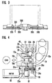
- the passage 19a is open at both ends with a coin discharging port 19b provided at the discharge end (Fig. 1) and an intake aperture 19c serving as a coin introducing port provided at the starting end (Figs. 4 and 5A).
- the coin lifting rail 19 has apertures 19d formed in the sheet metal sides of rail 19 just upstream of intake aperture 19C. Apertures 19d are sized so that the peripheries of rollers 17a, 17b protrude through them into the coin passage 19a. As a result, the upper roller 17a and lower roller 17b can each contact the respective face of the coin passing through the passage 19a, as best seen in Fig. 5A.
- the coin lifting rail 19 of this embodiment has a bend of about 90° and is inclined upward with a mild gradient as dictated by the relative positions of the sub-hopper 20 and main hopper 10.
- the coin lift rail 19 may take on other configurations if the relative positions of the sub-hopper 20 and main hopper 10 are changed.
- the upper roller 17a and lower roller 17b are located respectively above and below the coin lifting passage 19a.
- the rollers are typically made of rubber.
- the upper roller 17a and lower roller 17b are arranged with a space or gap therebetween so that the rollers lightly touch the faces of the coin being lifted.
- an upper roller gear 23a is fixed on the shaft of the upper roller 17a.
- a lower roller gear 23b is fixed on the shaft of the lower roller 17b on the other side.
- the upper roller gear 23a and lower roller gear 23b are typically made of a resin having high durability, such as POM (polyacetal).
- One end of the shaft of the lower roller 17b is linked via the gear box 18 with the rotary shaft of the motor 16, while the other end is supported by a support bearing 27 which is planted in a base 25.
- On the front face side of the roller mechanism are an upper idler gear 26a meshed with the upper roller gear 23a and a lower idler gear 26b meshed with the lower roller gear 23b.
- the two idler gears 26a, 26b are meshed with one another.
- Rotary shafts of the idler gears 26a, 26b extend across the coin transfer passage 19a in parallel with the rotary shafts of the upper and lower roller gears 23a, 23b.
- the idler gears 26a, 26b are supported by a support bearing 28 which is mounted on the base 25 on the front side and a support bearing 29 which is mounted on the base 25 on the other side.
- Idling levers 30a, 30b are provided on both sides of the coin transfer passage 19a, and loosely link the rotary shaft of the upper idler gear 26a and the rotary shaft of the upper roller gear 23a.
- Springs 31a, 31b are fastened at one end to respectively urge idling levers 30a, 30b in a counterclockwise direction, with the rotary shaft of the upper idler gear 26a serving as the fulcrum. Movement of the springs 31a, 31b is restricted by a stopper 32.
- the stopper 32 extends from the inner wall of a roller case 40 which encloses the entire roller mechanism or from the base 25.
- the idling lever 30a serves the function of coordinating with the spring 31a to adjust the space between the upper and lower rollers 17a, 17b.
- the idling lever 30b and spring 31b serve a similar function.
- the gap between the upper roller 17a and lower roller 17b is controlled to a size (e.g. 1 mm) that is slightly smaller than the thickness (e.g. 1.5 mm) of the coin by the biasing force of the springs 31a, 31b and the stopper 32.
- a size e.g. 1 mm
- the thickness e.g. 1.5 mm
- the coin lifting rail 19 has a notch on one side edge at a position near the upper and lower rollers 17a, 17b.
- a leaf spring 33 is bent adjacent its tip for engaging the notch to prevent coins from moving backward, as best seen in Fig. 4. This is achieved by arranging the bent portion at the tip of the leaf spring 33 to enter slightly into the coin passage 19a. The tip of the leaf spring 33 prevents the coins which have been fed by the upper and lower rollers 17a, 17b from returning in the reverse direction by gravity.
- the operation of the coin lifting mechanism in the slot machine of the automatic coin charging type shown in Fig. 1 is described as follows.
- the player rakes the coins contained in the coin tray 2 with a hand up to the step 2a and lets the coins drop through the coin charging slot 5 into the machine. This is all that the player needs to do because the machine automatically charges the coins that are dropped through the slot 5.
- the coins are guided through the chute 13 into the hopper container 21 in which they are accumulated.
- the rotary disk 200 of the hopper body 22 rotates to feed the coins out discretely in the tangential direction.
- the coins fed out of the hopper body 22 are screened when they reach the coin selector 14, which rejects improper coins and discharges them through the chute 15 to the return tray 4.
- Proper coins pass through the coin selector 14 with an inertia or momentum which they have acquired from being moved by the rotary disk 200.
- the coins then enter a duct or coin passage 19a defined by the coin lifting rail 19 through the intake aperture 19c where they are engaged between the upper roller 17a and lower roller 17b which drive them in a forward direction through rail passage 19a.
- the motor 16 rotates the rotary shaft of the gear box 18 to directly drive the lower roller 17b.
- the upper roller 17a is driven in rotation by the lower roller gear 23b through the lower idler gear 26b, the upper idler gear 26a, and the upper roller gear 23a.
- the coin held between the upper and lower rollers 17a, 17b is driven by both rollers as shown in Fig.
- the next coin fed out by the rotary disk 200 of the sub-hopper 20 is held between the upper and lower rollers 17a, 17b and transferred in a manner similar to that described for the first coin.
- the second coin leaves the rollers 17a, 17b, it contacts the preceding coin and pushes it forward in a sliding motion along the passage 19a.
- Subsequent coins are similarly transferred to push the preceding coins forward, thereby forming a series of coins in the passage which are in edge-to-edge contact with each other.
- the coins stacked edge-to-edge in passage 19a are advanced in increments equal to the diameter of the coins.
- Fig. 5B illustrates three coins C1, C2, C3 that are transferred successively from a low position to an elevated position.
- the coins are lined up in series and are in successive contact with preceding and/or subsequent coins.
- the driving force imparted onto the last coin by the upper and lower rollers 17a, 17b as it leaves the rollers pushes the preceding coins forward and upward.
- the rollers 17a, 17b advance the coins in sliding motion through the coin passage 19a by incremental displacements each being substantially equal to the size of the coins.
- the coins reach the top and are discharged one-by-one from the coin discharge port 19b at the end of the coin lifting rail 19 and fall into the hopper container 11 of the main hopper 10.
- the speed of lifting the coins by the coin lifting mechanism can be freely changed by adjusting the coin feeding speed, namely, the feeding speed of the rotary disk 200 of the sub-hopper 20, and the rotating speed of the upper and lower rollers 17a, 17b. It is easy to achieve a speed equal to or higher than the speed a player would manually charge coins with a conventional slot machine.
- the intake end of the coin lifting rail 19 is disposed slightly upstream of the coin lifting mechanism in the presently preferred embodiment shown in Figs. 4-5B, it may alternatively coincide with or be disposed just downstream of the coin lifting mechanism so that the coins are driven by the mechanism from the beginning of the coin lifting rail 19.
- the configuration of the coin lifting rail is not restricted to that described in the embodiment.
- the central portion of the rail 19 on one side may be open along the longitudinal direction so that part of the coins being lifted can be seen from the outside.
- the coin lifting mechanism of the invention can lift and transfer coins reliably from a low position to a high position, where the force of feeding out the coins cannot be utilized to lift the coins.
- an automatic coin charging machine can be achieved as described above.
- the tedious operation of manually charging coins one-by-one in conventional slot machines can be eliminated.
- the coins are driven by roller peripheries that engage the faces of the coins, they are lifted reliably and the lifting speed is adjustable.
- the coin lifting mechanism of the invention can be used in game machines that use coins, automatic vendors, automatic cash dispensers, automatic money changing machines, and the like.
Landscapes
- Physics & Mathematics (AREA)
- General Physics & Mathematics (AREA)
- Slot Machines And Peripheral Devices (AREA)
- Acyclic And Carbocyclic Compounds In Medicinal Compositions (AREA)
- Pharmaceuticals Containing Other Organic And Inorganic Compounds (AREA)
- Control Of Vending Devices And Auxiliary Devices For Vending Devices (AREA)
- Pinball Game Machines (AREA)
Claims (13)
- Mécanisme élévateur de pièce destiné à soulever des pièces, le mécanisme élévateur de pièce comportant :une paire de corps rotatifs (17a, 17b) ayant des surfaces rotatives espacées qui sont poussées élastiquement l'une vers l'autre afin de tenir des pièces entre elles, les corps tournant dans des directions opposées afin de produire une force d'entraínement dans une direction d'entraínement des pièces une par une au-delà des corps; etun rail d'élévation de pièce (19) s'étendant depuis une extrémité de réception de pièce disposée de façon adjacente à la paire de corps rotatifs vers le haut jusqu'à une extrémité de déchargement de pièce, le rail d'élévation de pièce ayant un passage de pièce (19a) à travers lequel les pièces entraínées au-delà des corps rotatifs glissent en série et en contact bord à bord sous l'effet de ladite force d'entraínement vers l'extrémité de déchargement de pièce.
- Mécanisme élévateur de pièce selon la revendication 1, dans lequel la paire de corps rotatifs comprend une paire de rouleaux (17a, 17b) ayant des surfaces rotatives sensiblement circulaires.
- Mécanisme élévateur de pièce selon la revendication 1 ou la revendication 2, dans lequel le sens de la force d'entraínement est sensiblement tangent aux surfaces rotatives.
- Mécanisme élévateur de pièce selon l'une quelconque des revendications précédentes, dans lequel le rail d'élévation de pièce s'étend depuis l'extrémité de réception de pièce sensiblement dans la direction de la force d'entraínement.
- Mécanisme élévateur de pièce selon l'une quelconque des revendications précédentes, dans lequel le rail d'élévation de pièce s'étend de manière non linéaire depuis l'extrémité de réception de pièce jusqu'à l'extrémité de déchargement de pièce.
- Mécanisme élévateur de pièce selon l'une quelconque des revendications précédentes, comportant une butée (32) destinée à espacer la paire de surfaces rotatives d'un espace minimum.
- Mécanisme élévateur de pièce selon la revendication 6, dans lequel l'espace minimum est légèrement plus petit qu'une épaisseur des pièces.
- Mécanisme élévateur de pièce selon la revendication 6 ou la revendication 7, dans lequel la butée est réglable afin d'ajuster l'espace minimum.
- Mécanisme élévateur de pièce selon l'une quelconque des revendications précédentes, comportant en outre un mécanisme de prévention de mouvement en sens inverse (33) relié au rail d'élévation de pièce afin d'empêcher les pièces disposées dans le passage de pièce de glisser en arrière vers l'extrémité de réception de pièce.
- Mécanisme élévateur de pièce selon la revendication 9, dans lequel le mécanisme de prévention de mouvement en sens inverse comporte un ressort à lame plié (33) engageant une fente du passage de pièce à l'extrémité de réception de pièce.
- Mécanisme élévateur de pièce selon l'une quelconque des revendications précédentes, dans lequel le passage de pièce comprend un canal sensiblement uniforme ayant une largeur légèrement plus grande qu'un diamètre des pièces et une profondeur légèrement plus grande qu'une épaisseur des pièces.
- Mécanisme élévateur de pièce selon l'une quelconque des revendications précédentes, dans lequel le rail d'élévation de pièce comprend une paire de feuilles espacées par une entretoise afin de former le passage de pièce entre elles.
- Procédé d'élévation de pièces depuis un point relativement bas jusqu'à un point relativement haut, le procédé comportant les étapes consistant à prévoir une piste capable de maintenir des pièces en contact bord à bord entre une extrémité d'entrée de la piste proche du point bas et une extrémité de sortie de la piste proche des points hauts; placer un certain nombre de pièces dans la piste de telle sorte que les pièces en contact bord à bord s'étendent depuis environ l'extrémité d'entrée jusqu'à environ l'extrémité de sortie; engager avec friction des faces de la pièce avec des première et deuxième surfaces mobiles; et régler les surfaces mobiles alors qu'elles sont en contact de friction avec les faces en mouvement afin d'avancer ainsi une pièce proche de l'extrémité d'entrée, et en conséquence le nombre de pièces dans la piste, vers l'extrémité de sortie de telle sorte qu'une pièce la plus proche de l'extrémité de sortie est évacuée de la piste.
Applications Claiming Priority (3)
| Application Number | Priority Date | Filing Date | Title |
|---|---|---|---|
| JP211813/97 | 1997-08-06 | ||
| JP21181397 | 1997-08-06 | ||
| JP9211813A JPH1153610A (ja) | 1997-08-06 | 1997-08-06 | コイン揚送機構 |
Publications (2)
| Publication Number | Publication Date |
|---|---|
| EP0896302A1 EP0896302A1 (fr) | 1999-02-10 |
| EP0896302B1 true EP0896302B1 (fr) | 2002-09-25 |
Family
ID=16612028
Family Applications (1)
| Application Number | Title | Priority Date | Filing Date |
|---|---|---|---|
| EP98305447A Expired - Lifetime EP0896302B1 (fr) | 1997-08-06 | 1998-07-08 | Elévateur pour pièces de monnaie |
Country Status (7)
| Country | Link |
|---|---|
| US (1) | US6095916A (fr) |
| EP (1) | EP0896302B1 (fr) |
| JP (1) | JPH1153610A (fr) |
| AT (1) | ATE225063T1 (fr) |
| AU (1) | AU737630B2 (fr) |
| DE (1) | DE69808204T2 (fr) |
| ZA (1) | ZA986187B (fr) |
Families Citing this family (19)
| Publication number | Priority date | Publication date | Assignee | Title |
|---|---|---|---|---|
| JP2000107354A (ja) * | 1998-10-02 | 2000-04-18 | Aruze Corp | 遊技機用コイン払出装置 |
| US6193599B1 (en) * | 1998-10-20 | 2001-02-27 | Asahi Seiko Co., Ltd. | Coin hopper device |
| US6267663B1 (en) * | 1999-02-04 | 2001-07-31 | Mag-Nif Incorporated | Modular coin handling and sorting apparatus |
| SE520989C2 (sv) * | 1999-12-23 | 2003-09-23 | Scan Coin Ind Ab | Tillbehör för en mynthanteringsapparat |
| TW472218B (en) | 2000-01-28 | 2002-01-11 | Asahi Seiko Co Ltd | Coin hopper |
| JP2002117428A (ja) * | 2000-10-06 | 2002-04-19 | Asahi Seiko Kk | コインホッパ |
| US7048623B2 (en) * | 2001-02-09 | 2006-05-23 | Mag-Nif Incorporated | Coin separator and sorter assembly |
| JP4411383B2 (ja) * | 2003-11-11 | 2010-02-10 | 旭精工株式会社 | コイン送り出し装置のコイン逆行防止装置 |
| US7533490B2 (en) * | 2005-06-30 | 2009-05-19 | Innovated Agricultural Concepts, Llc | Method for creating a verified food source |
| KR100911991B1 (ko) | 2008-01-11 | 2009-08-13 | 주식회사 디에이테크놀로지 | 주화 공급 장치 |
| US8522950B2 (en) * | 2011-09-09 | 2013-09-03 | Outerwall Inc. | Debris diverter for coin counting machine and associated method of manufacture and operation |
| US9036890B2 (en) | 2012-06-05 | 2015-05-19 | Outerwall Inc. | Optical coin discrimination systems and methods for use with consumer-operated kiosks and the like |
| US8967361B2 (en) | 2013-02-27 | 2015-03-03 | Outerwall Inc. | Coin counting and sorting machines |
| US9022841B2 (en) | 2013-05-08 | 2015-05-05 | Outerwall Inc. | Coin counting and/or sorting machines and associated systems and methods |
| US9235945B2 (en) | 2014-02-10 | 2016-01-12 | Outerwall Inc. | Coin input apparatuses and associated methods and systems |
| DE102014117281B3 (de) * | 2014-11-25 | 2016-03-31 | Löwen Entertainment GmbH | Münzverarbeitungseinrichtung |
| JP6402332B2 (ja) * | 2015-09-09 | 2018-10-10 | 旭精工株式会社 | コインホッパー |
| CN106056744B (zh) * | 2016-06-30 | 2018-11-09 | 西安交通大学 | 一种硬币清分机 |
| US20250010173A1 (en) * | 2023-07-04 | 2025-01-09 | Guangzhou small potato Animation Technology Co., LTD | Automatic circulation structure device for a table air hockey |
Family Cites Families (7)
| Publication number | Priority date | Publication date | Assignee | Title |
|---|---|---|---|---|
| US719459A (en) * | 1902-04-21 | 1903-02-03 | Henry Goetze | Coin-counting device. |
| US1808270A (en) * | 1926-10-29 | 1931-06-02 | Vogt Curt | Counting machine |
| JPH01213779A (ja) * | 1987-06-18 | 1989-08-28 | Internatl Business Mach Corp <Ibm> | 硬貨処理装置 |
| JPS63314868A (ja) * | 1987-10-03 | 1988-12-22 | Nec Corp | Mos半導体装置の製造方法 |
| US5232398A (en) * | 1991-02-20 | 1993-08-03 | Himecs Co., Ltd. | Disc conveyor |
| JPH0528340A (ja) * | 1991-07-19 | 1993-02-05 | Asahi Seiko Kk | コイン送出装置 |
| JP3153873B2 (ja) | 1993-10-18 | 2001-04-09 | アルゼ株式会社 | ホッパー装置 |
-
1997
- 1997-08-06 JP JP9211813A patent/JPH1153610A/ja not_active Withdrawn
-
1998
- 1998-07-08 AT AT98305447T patent/ATE225063T1/de active
- 1998-07-08 DE DE69808204T patent/DE69808204T2/de not_active Expired - Lifetime
- 1998-07-08 AU AU75060/98A patent/AU737630B2/en not_active Ceased
- 1998-07-08 EP EP98305447A patent/EP0896302B1/fr not_active Expired - Lifetime
- 1998-07-13 ZA ZA986187A patent/ZA986187B/xx unknown
- 1998-07-17 US US09/118,476 patent/US6095916A/en not_active Expired - Lifetime
Also Published As
| Publication number | Publication date |
|---|---|
| ZA986187B (en) | 1999-02-10 |
| ATE225063T1 (de) | 2002-10-15 |
| JPH1153610A (ja) | 1999-02-26 |
| US6095916A (en) | 2000-08-01 |
| DE69808204D1 (de) | 2002-10-31 |
| AU7506098A (en) | 1999-02-18 |
| AU737630B2 (en) | 2001-08-23 |
| EP0896302A1 (fr) | 1999-02-10 |
| DE69808204T2 (de) | 2003-08-14 |
Similar Documents
| Publication | Publication Date | Title |
|---|---|---|
| EP0896302B1 (fr) | Elévateur pour pièces de monnaie | |
| US6499277B1 (en) | Coin wrapper | |
| US6276678B1 (en) | Cash drawer for an automatic teller | |
| EP1657685B1 (fr) | Système de distinction de dénomination dans un appareil de traitement de pièces de monnaie | |
| JPH0512212B2 (fr) | ||
| EP0469886A2 (fr) | Courroie pour le transport successif de pièces de monnaie | |
| US5170874A (en) | Coin conveyor for successively transporting coins | |
| JP2006230541A (ja) | 紙幣識別装置および遊技媒体の貸し出し機 | |
| CN111017342B (zh) | 全自动硬币清分包装流程控制系统 | |
| JPH03171280A (ja) | 硬貨選別装置 | |
| JP3267697B2 (ja) | 硬貨処理機 | |
| JPH07152945A (ja) | 硬貨繰出装置 | |
| JP3857860B2 (ja) | 硬貨集積投出装置 | |
| JP7784732B2 (ja) | コイン処理装置 | |
| JP3361287B2 (ja) | 紙幣搬送ユニット | |
| JP4099750B2 (ja) | 紙幣一時保留装置 | |
| JP4391849B2 (ja) | 硬貨入出金機 | |
| JP3041727B2 (ja) | ソータ | |
| JP2576906Y2 (ja) | ソータ | |
| JP2548877Y2 (ja) | 硬貨収納投出装置 | |
| JPH03225587A (ja) | 硬貨選別装置 | |
| JP2547237Y2 (ja) | 硬貨収納投出装置 | |
| JP2001347050A (ja) | メダル等の押上げ搬送装置 | |
| JP2560617Y2 (ja) | 硬貨処理装置 | |
| JPS63249287A (ja) | 硬貨選別通路装置 |
Legal Events
| Date | Code | Title | Description |
|---|---|---|---|
| PUAI | Public reference made under article 153(3) epc to a published international application that has entered the european phase |
Free format text: ORIGINAL CODE: 0009012 |
|
| AK | Designated contracting states |
Kind code of ref document: A1 Designated state(s): AT CH DE FR GB LI |
|
| AX | Request for extension of the european patent |
Free format text: AL;LT;LV;MK;RO;SI |
|
| 17P | Request for examination filed |
Effective date: 19990205 |
|
| RAP1 | Party data changed (applicant data changed or rights of an application transferred) |
Owner name: ARUZE CORPORATION |
|
| AKX | Designation fees paid |
Free format text: AT CH DE FR GB LI |
|
| 17Q | First examination report despatched |
Effective date: 20000410 |
|
| GRAG | Despatch of communication of intention to grant |
Free format text: ORIGINAL CODE: EPIDOS AGRA |
|
| GRAG | Despatch of communication of intention to grant |
Free format text: ORIGINAL CODE: EPIDOS AGRA |
|
| GRAH | Despatch of communication of intention to grant a patent |
Free format text: ORIGINAL CODE: EPIDOS IGRA |
|
| GRAH | Despatch of communication of intention to grant a patent |
Free format text: ORIGINAL CODE: EPIDOS IGRA |
|
| GRAA | (expected) grant |
Free format text: ORIGINAL CODE: 0009210 |
|
| AK | Designated contracting states |
Kind code of ref document: B1 Designated state(s): AT CH DE FR GB LI |
|
| REF | Corresponds to: |
Ref document number: 225063 Country of ref document: AT Date of ref document: 20021015 Kind code of ref document: T |
|
| REG | Reference to a national code |
Ref country code: GB Ref legal event code: FG4D |
|
| REG | Reference to a national code |
Ref country code: CH Ref legal event code: EP |
|
| REF | Corresponds to: |
Ref document number: 69808204 Country of ref document: DE Date of ref document: 20021031 |
|
| REG | Reference to a national code |
Ref country code: CH Ref legal event code: NV Representative=s name: ROTTMANN, ZIMMERMANN + PARTNER AG |
|
| ET | Fr: translation filed | ||
| PLBE | No opposition filed within time limit |
Free format text: ORIGINAL CODE: 0009261 |
|
| STAA | Information on the status of an ep patent application or granted ep patent |
Free format text: STATUS: NO OPPOSITION FILED WITHIN TIME LIMIT |
|
| 26N | No opposition filed |
Effective date: 20030626 |
|
| REG | Reference to a national code |
Ref country code: CH Ref legal event code: PFA Owner name: UNIVERSAL ENTERTAINMENT CORPORATION Free format text: ARUZE CORPORATION#1-25, ARIAKE 3-CHOME, KOUTOU-KU#TOKYO (JP) -TRANSFER TO- UNIVERSAL ENTERTAINMENT CORPORATION#ARIAKE FRONTIER BUILDING, TOWER A, 3-7-26 ARIAKE KOTO-KU#TOKYO (JP) |
|
| REG | Reference to a national code |
Ref country code: CH Ref legal event code: PFA Owner name: UNIVERSAL ENTERTAINMENT CORPORATION Free format text: UNIVERSAL ENTERTAINMENT CORPORATION#ARIAKE FRONTIER BUILDING, TOWER A, 3-7-26 ARIAKE KOTO-KU#TOKYO (JP) -TRANSFER TO- UNIVERSAL ENTERTAINMENT CORPORATION#ARIAKE FRONTIER BUILDING, TOWER A, 3-7-26 ARIAKE KOTO-KU#TOKYO (JP) |
|
| PGFP | Annual fee paid to national office [announced via postgrant information from national office to epo] |
Ref country code: CH Payment date: 20110725 Year of fee payment: 14 Ref country code: FR Payment date: 20110729 Year of fee payment: 14 |
|
| PGFP | Annual fee paid to national office [announced via postgrant information from national office to epo] |
Ref country code: AT Payment date: 20110714 Year of fee payment: 14 |
|
| REG | Reference to a national code |
Ref country code: DE Ref legal event code: R082 Ref document number: 69808204 Country of ref document: DE Representative=s name: PFENNING MEINIG & PARTNER GBR, DE |
|
| REG | Reference to a national code |
Ref country code: DE Ref legal event code: R082 Ref document number: 69808204 Country of ref document: DE Representative=s name: PFENNING, MEINIG & PARTNER MBB PATENTANWAELTE, DE Effective date: 20120423 Ref country code: DE Ref legal event code: R082 Ref document number: 69808204 Country of ref document: DE Representative=s name: PFENNING MEINIG & PARTNER GBR, DE Effective date: 20120423 Ref country code: DE Ref legal event code: R081 Ref document number: 69808204 Country of ref document: DE Owner name: UNIVERSAL ENTERTAINMENT CORP., JP Free format text: FORMER OWNER: ARUZE CORP., TOKIO/TOKYO, JP Effective date: 20120423 |
|
| REG | Reference to a national code |
Ref country code: AT Ref legal event code: HC Ref document number: 225063 Country of ref document: AT Kind code of ref document: T Owner name: UNIVERSAL ENTERTAINMENT CORPORATION, JP Effective date: 20120427 |
|
| REG | Reference to a national code |
Ref country code: CH Ref legal event code: PL |
|
| REG | Reference to a national code |
Ref country code: AT Ref legal event code: MM01 Ref document number: 225063 Country of ref document: AT Kind code of ref document: T Effective date: 20120708 |
|
| REG | Reference to a national code |
Ref country code: FR Ref legal event code: ST Effective date: 20130329 |
|
| PG25 | Lapsed in a contracting state [announced via postgrant information from national office to epo] |
Ref country code: CH Free format text: LAPSE BECAUSE OF NON-PAYMENT OF DUE FEES Effective date: 20120731 Ref country code: FR Free format text: LAPSE BECAUSE OF NON-PAYMENT OF DUE FEES Effective date: 20120731 Ref country code: LI Free format text: LAPSE BECAUSE OF NON-PAYMENT OF DUE FEES Effective date: 20120731 |
|
| PG25 | Lapsed in a contracting state [announced via postgrant information from national office to epo] |
Ref country code: AT Free format text: LAPSE BECAUSE OF NON-PAYMENT OF DUE FEES Effective date: 20120708 |
|
| PGFP | Annual fee paid to national office [announced via postgrant information from national office to epo] |
Ref country code: DE Payment date: 20150721 Year of fee payment: 18 Ref country code: GB Payment date: 20150721 Year of fee payment: 18 |
|
| REG | Reference to a national code |
Ref country code: DE Ref legal event code: R119 Ref document number: 69808204 Country of ref document: DE |
|
| GBPC | Gb: european patent ceased through non-payment of renewal fee |
Effective date: 20160708 |
|
| PG25 | Lapsed in a contracting state [announced via postgrant information from national office to epo] |
Ref country code: DE Free format text: LAPSE BECAUSE OF NON-PAYMENT OF DUE FEES Effective date: 20170201 |
|
| PG25 | Lapsed in a contracting state [announced via postgrant information from national office to epo] |
Ref country code: GB Free format text: LAPSE BECAUSE OF NON-PAYMENT OF DUE FEES Effective date: 20160708 |