EP0896391A2 - Steckverbinderhülse - Google Patents
Steckverbinderhülse Download PDFInfo
- Publication number
- EP0896391A2 EP0896391A2 EP98111974A EP98111974A EP0896391A2 EP 0896391 A2 EP0896391 A2 EP 0896391A2 EP 98111974 A EP98111974 A EP 98111974A EP 98111974 A EP98111974 A EP 98111974A EP 0896391 A2 EP0896391 A2 EP 0896391A2
- Authority
- EP
- European Patent Office
- Prior art keywords
- plug
- region
- connector sleeve
- contact
- sleeve according
- Prior art date
- Legal status (The legal status is an assumption and is not a legal conclusion. Google has not performed a legal analysis and makes no representation as to the accuracy of the status listed.)
- Granted
Links
Images

Classifications
-
- H—ELECTRICITY
- H01—ELECTRIC ELEMENTS
- H01R—ELECTRICALLY-CONDUCTIVE CONNECTIONS; STRUCTURAL ASSOCIATIONS OF A PLURALITY OF MUTUALLY-INSULATED ELECTRICAL CONNECTING ELEMENTS; COUPLING DEVICES; CURRENT COLLECTORS
- H01R13/00—Details of coupling devices of the kinds covered by groups H01R12/70 or H01R24/00 - H01R33/00
- H01R13/02—Contact members
- H01R13/10—Sockets for co-operation with pins or blades
- H01R13/11—Resilient sockets
- H01R13/113—Resilient sockets co-operating with pins or blades having a rectangular transverse section
-
- H—ELECTRICITY
- H01—ELECTRIC ELEMENTS
- H01R—ELECTRICALLY-CONDUCTIVE CONNECTIONS; STRUCTURAL ASSOCIATIONS OF A PLURALITY OF MUTUALLY-INSULATED ELECTRICAL CONNECTING ELEMENTS; COUPLING DEVICES; CURRENT COLLECTORS
- H01R13/00—Details of coupling devices of the kinds covered by groups H01R12/70 or H01R24/00 - H01R33/00
- H01R13/02—Contact members
- H01R13/15—Pins, blades or sockets having separate spring member for producing or increasing contact pressure
- H01R13/18—Pins, blades or sockets having separate spring member for producing or increasing contact pressure with the spring member surrounding the socket
Definitions
- the present invention relates to a plug-in connector sleeve according to the preamble of Patent Claim 1.
- a plug-in connector sleeve is disclosed in German Patent 21 48 805.
- plug-in connector sleeves are applied, in particular, in automobiles, where they are exposed to adverse external circumstances such as vibrations and dirt.
- Conventional plug-in connector sleeves of this type permit the plug parts to vibrate relative to one another to an extent which can lead to fretting corrosion on the contact points, the result being an increase in the contact resistance.
- Micromovements caused by thermal expansion, or vibrations can expose a surface which in turn is oxidized and grows to form an insulating layer, entailing poorer contact.
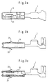
- the plug-in connector sleeve 1 shown in Figure 1 has a plug-in region 2 and a conductor connection region 3.
- the plug-in region has the form of a housing 4 in the shape of a box and has two side walls 5, 6, a floor 7 and a roof 8.
- centring web 17 Connected to the two side walls 5 and 6 and located at the front on the plug-in region 2 is a centring web 17 which, in conjunction with a slip-on spring 19 (see Figure 3), facilitates plugging a flat connector without any problem.
- a middle web 18 serves to stiffen the plug-in region 2 and to guide the slip-on spring 19 (see Figure 3).
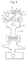
- Figure 2 shows a sheet-metal blank of the plug-in connector sleeve.
- the floor of the box-shaped housing is formed by the contact segment 11 with its free end 14 with the contact segment 10 with its free end 15.
- the two side walls 5 and 6 are bent upwards from the sheet-metal blank.
- the roof 8 of the housing is formed by the two contact segments 12 and 13.
- the four contact segments 9 to 12 are bent with their free ends 13 to 16 into the interior of the housing, so that they enclose an angle of less than 90° with the walls 5 and 6.
- the two upper contact segments 9 and 12 and the two lower contact segments 10 and 11 mutually overlap one another, as may be seen in Figure 1A in Section C-C. Owing to the over-lapping of the segments 9 to 12, the free ends 13 to 16 have contact lines situated apart from one another, thus enhancing the static precision of the system. The result is improved protection against vibrations and a greater resistance to corrosion.
- the front centring web 17 and the middle web 18 are fastened to the side walls 5 and 6, in order to reduce the spring action of the contact segments 9 to 12.
- the result of the special position of the contact segments 9 to 12 is that when a flat connector slides in the two spring-like contact segments 10 to 13 are firstly deflected, which facilitates insertion, and the two rear contact segments 10 and 12 are not deflected until later depths of insertion, with the result that the full contact force is then achieved.
- the floor has a cutout 21 in which the slip-on spring of Figure 3 can be fastened.
- the slip-on spring 19 can be produced from a hard elastic material such as steel, for example. It has inwardly rounded edges in the front region, in order to facilitate plugging in a flat connector.
- the aim of the slip-on spring 19 is to prevent asymmetric insertion of a flat connector from bending outwards the lower contact segments 10, 11 and the upper contact segments 9, 12.
- the plug-in connector sleeve according to the invention proves to be extremely compact and robust in shape, which renders it possible for the plug-in connection sleeve to be produced simply and in a way which can be automated. Furthermore, assembly rotated by 180° is possible because of the symmetrical design of the contact segments.
Landscapes
- Connector Housings Or Holding Contact Members (AREA)
- Details Of Connecting Devices For Male And Female Coupling (AREA)
Applications Claiming Priority (2)
| Application Number | Priority Date | Filing Date | Title |
|---|---|---|---|
| DE19734523A DE19734523C2 (de) | 1997-08-08 | 1997-08-08 | Steckverbinderhülse |
| DE19734523 | 1997-08-08 |
Publications (3)
| Publication Number | Publication Date |
|---|---|
| EP0896391A2 true EP0896391A2 (de) | 1999-02-10 |
| EP0896391A3 EP0896391A3 (de) | 2000-08-23 |
| EP0896391B1 EP0896391B1 (de) | 2004-05-26 |
Family
ID=7838478
Family Applications (1)
| Application Number | Title | Priority Date | Filing Date |
|---|---|---|---|
| EP98111974A Expired - Lifetime EP0896391B1 (de) | 1997-08-08 | 1998-06-29 | Steckverbinderhülse |
Country Status (6)
| Country | Link |
|---|---|
| EP (1) | EP0896391B1 (de) |
| KR (1) | KR100574570B1 (de) |
| AT (1) | ATE268062T1 (de) |
| BR (1) | BR9802873A (de) |
| CA (1) | CA2242436A1 (de) |
| DE (1) | DE19734523C2 (de) |
Cited By (2)
| Publication number | Priority date | Publication date | Assignee | Title |
|---|---|---|---|---|
| WO2017102725A1 (fr) * | 2015-12-17 | 2017-06-22 | Delphi International Operations Luxembourg S.À R.L. | Contact femelle avec lames latérales de maintien pour contact mâle et ensemble de connexion comportant de tels contacts femelle et mâle |
| DE102018119999A1 (de) * | 2018-08-16 | 2020-02-20 | Te Connectivity Germany Gmbh | Elektrische Kontaktvorrichtung für ein elektrisches Kabel |
Family Cites Families (3)
| Publication number | Priority date | Publication date | Assignee | Title |
|---|---|---|---|---|
| DE1590632C3 (de) * | 1965-02-13 | 1979-02-22 | Bunker Ramo Corp., Oak Brook, Ill. (V.St.A.) | Elektrischer Buchsenkontakt |
| DE8914951U1 (de) * | 1989-12-18 | 1991-04-18 | Grote & Hartmann Gmbh & Co Kg, 5600 Wuppertal | Elektrisches Kontaktelement mit einer Überfeder |
| WO1997048149A1 (en) * | 1996-06-14 | 1997-12-18 | Framatome Connectors International | Pin bushing |
-
1997
- 1997-08-08 DE DE19734523A patent/DE19734523C2/de not_active Expired - Fee Related
-
1998
- 1998-06-29 EP EP98111974A patent/EP0896391B1/de not_active Expired - Lifetime
- 1998-06-29 AT AT98111974T patent/ATE268062T1/de not_active IP Right Cessation
- 1998-07-07 CA CA002242436A patent/CA2242436A1/en not_active Abandoned
- 1998-08-07 BR BR9802873-1A patent/BR9802873A/pt not_active Application Discontinuation
- 1998-08-07 KR KR1019980032112A patent/KR100574570B1/ko not_active Expired - Fee Related
Cited By (5)
| Publication number | Priority date | Publication date | Assignee | Title |
|---|---|---|---|---|
| WO2017102725A1 (fr) * | 2015-12-17 | 2017-06-22 | Delphi International Operations Luxembourg S.À R.L. | Contact femelle avec lames latérales de maintien pour contact mâle et ensemble de connexion comportant de tels contacts femelle et mâle |
| FR3045964A1 (fr) * | 2015-12-17 | 2017-06-23 | Delphi Int Operations Luxembourg Sarl | Contact femelle avec lames laterales de maintien pour contact male et ensemble de connexion comportant de tels contacts femelle et male |
| CN108370112A (zh) * | 2015-12-17 | 2018-08-03 | 德尔福国际业务卢森堡公司 | 用于公接头的具有横向保持片的母接头以及包括这种母接头和公接头的连接组装件 |
| JP2018537832A (ja) * | 2015-12-17 | 2018-12-20 | デルフィ・インターナショナル・オペレーションズ・ルクセンブルク・エス・アー・エール・エル | 雄端子のための側方保持ブレードを備えた雌端子、ならびにそのような雌端子および雄端子を含んだ接続アセンブリ |
| DE102018119999A1 (de) * | 2018-08-16 | 2020-02-20 | Te Connectivity Germany Gmbh | Elektrische Kontaktvorrichtung für ein elektrisches Kabel |
Also Published As
| Publication number | Publication date |
|---|---|
| KR19990023435A (ko) | 1999-03-25 |
| DE19734523C2 (de) | 1999-07-29 |
| ATE268062T1 (de) | 2004-06-15 |
| EP0896391B1 (de) | 2004-05-26 |
| EP0896391A3 (de) | 2000-08-23 |
| CA2242436A1 (en) | 1999-02-08 |
| DE19734523A1 (de) | 1999-02-25 |
| BR9802873A (pt) | 1999-10-19 |
| KR100574570B1 (ko) | 2006-08-10 |
Similar Documents
| Publication | Publication Date | Title |
|---|---|---|
| EP0818855B1 (de) | Verbinder | |
| US5951336A (en) | Terminal fitting | |
| JP2675698B2 (ja) | 電気接触端子 | |
| EP0971446B1 (de) | Zweiteilige elektrische Anschlussklemme | |
| US5989079A (en) | Male side terminal fitting | |
| WO2000014828A1 (en) | Socket contact for electrical connectors | |
| US6390860B2 (en) | Connector with a terminal deflection preventing mechanism | |
| JPH07307180A (ja) | リセプタクル型コンタクト | |
| US20020160666A1 (en) | Electrical contact | |
| US6217379B1 (en) | Plug-in contact | |
| JP6367600B2 (ja) | コネクタ | |
| EP0896391B1 (de) | Steckverbinderhülse | |
| JP5528853B2 (ja) | 弁体の取付構造 | |
| EP0809327B1 (de) | Batterieklemme für ein Kraftfahrzeug | |
| JP3278017B2 (ja) | リセプタクルコンタクト | |
| US6132232A (en) | Connector locking construction for a connector receptacle of an automotive electrical connection box | |
| EP0851550B1 (de) | Metallischer Schirm für eine Zündkerze | |
| US6200174B1 (en) | Connecting terminal | |
| JP4316430B2 (ja) | 積み重ね型アース端子 | |
| KR20050065332A (ko) | 전기 커넥터 조립체 | |
| TW202332138A (zh) | 連接器以及組件 | |
| JP4048102B2 (ja) | モジュラージャック | |
| JPH07312815A (ja) | カバー誤嵌合防止電気接続箱 | |
| JP7290544B2 (ja) | 雌端子 | |
| US6287157B1 (en) | Connector assembly |
Legal Events
| Date | Code | Title | Description |
|---|---|---|---|
| PUAI | Public reference made under article 153(3) epc to a published international application that has entered the european phase |
Free format text: ORIGINAL CODE: 0009012 |
|
| AK | Designated contracting states |
Kind code of ref document: A2 Designated state(s): AT BE ES FR GB IT SE |
|
| AX | Request for extension of the european patent |
Free format text: AL;LT;LV;MK;RO;SI |
|
| PUAL | Search report despatched |
Free format text: ORIGINAL CODE: 0009013 |
|
| AK | Designated contracting states |
Kind code of ref document: A3 Designated state(s): AT BE CH CY DE DK ES FI FR GB GR IE IT LI LU MC NL PT SE |
|
| AX | Request for extension of the european patent |
Free format text: AL;LT;LV;MK;RO;SI |
|
| 17P | Request for examination filed |
Effective date: 20001227 |
|
| AKX | Designation fees paid |
Free format text: AT BE ES FR GB IT SE |
|
| GRAP | Despatch of communication of intention to grant a patent |
Free format text: ORIGINAL CODE: EPIDOSNIGR1 |
|
| GRAS | Grant fee paid |
Free format text: ORIGINAL CODE: EPIDOSNIGR3 |
|
| GRAA | (expected) grant |
Free format text: ORIGINAL CODE: 0009210 |
|
| RAP1 | Party data changed (applicant data changed or rights of an application transferred) |
Owner name: FCI |
|
| AK | Designated contracting states |
Kind code of ref document: B1 Designated state(s): AT BE ES FR GB IT SE |
|
| PG25 | Lapsed in a contracting state [announced via postgrant information from national office to epo] |
Ref country code: IT Free format text: LAPSE BECAUSE OF FAILURE TO SUBMIT A TRANSLATION OF THE DESCRIPTION OR TO PAY THE FEE WITHIN THE PRESCRIBED TIME-LIMIT;WARNING: LAPSES OF ITALIAN PATENTS WITH EFFECTIVE DATE BEFORE 2007 MAY HAVE OCCURRED AT ANY TIME BEFORE 2007. THE CORRECT EFFECTIVE DATE MAY BE DIFFERENT FROM THE ONE RECORDED. Effective date: 20040526 Ref country code: BE Free format text: LAPSE BECAUSE OF FAILURE TO SUBMIT A TRANSLATION OF THE DESCRIPTION OR TO PAY THE FEE WITHIN THE PRESCRIBED TIME-LIMIT Effective date: 20040526 Ref country code: AT Free format text: LAPSE BECAUSE OF FAILURE TO SUBMIT A TRANSLATION OF THE DESCRIPTION OR TO PAY THE FEE WITHIN THE PRESCRIBED TIME-LIMIT Effective date: 20040526 |
|
| REG | Reference to a national code |
Ref country code: GB Ref legal event code: FG4D |
|
| REG | Reference to a national code |
Ref country code: DE Ref legal event code: 8566 |
|
| PG25 | Lapsed in a contracting state [announced via postgrant information from national office to epo] |
Ref country code: SE Free format text: LAPSE BECAUSE OF FAILURE TO SUBMIT A TRANSLATION OF THE DESCRIPTION OR TO PAY THE FEE WITHIN THE PRESCRIBED TIME-LIMIT Effective date: 20040826 |
|
| PG25 | Lapsed in a contracting state [announced via postgrant information from national office to epo] |
Ref country code: ES Free format text: LAPSE BECAUSE OF FAILURE TO SUBMIT A TRANSLATION OF THE DESCRIPTION OR TO PAY THE FEE WITHIN THE PRESCRIBED TIME-LIMIT Effective date: 20040906 |
|
| ET | Fr: translation filed | ||
| PLBE | No opposition filed within time limit |
Free format text: ORIGINAL CODE: 0009261 |
|
| STAA | Information on the status of an ep patent application or granted ep patent |
Free format text: STATUS: NO OPPOSITION FILED WITHIN TIME LIMIT |
|
| 26N | No opposition filed |
Effective date: 20050301 |
|
| PGFP | Annual fee paid to national office [announced via postgrant information from national office to epo] |
Ref country code: GB Payment date: 20050629 Year of fee payment: 8 |
|
| PG25 | Lapsed in a contracting state [announced via postgrant information from national office to epo] |
Ref country code: GB Free format text: LAPSE BECAUSE OF NON-PAYMENT OF DUE FEES Effective date: 20060629 |
|
| GBPC | Gb: european patent ceased through non-payment of renewal fee |
Effective date: 20060629 |
|
| PGFP | Annual fee paid to national office [announced via postgrant information from national office to epo] |
Ref country code: FR Payment date: 20090605 Year of fee payment: 12 |
|
| REG | Reference to a national code |
Ref country code: FR Ref legal event code: ST Effective date: 20110228 |
|
| PG25 | Lapsed in a contracting state [announced via postgrant information from national office to epo] |
Ref country code: FR Free format text: LAPSE BECAUSE OF NON-PAYMENT OF DUE FEES Effective date: 20100630 |