EP0896409A2 - Dérivation pour câble d'énergie - Google Patents
Dérivation pour câble d'énergie Download PDFInfo
- Publication number
- EP0896409A2 EP0896409A2 EP98401776A EP98401776A EP0896409A2 EP 0896409 A2 EP0896409 A2 EP 0896409A2 EP 98401776 A EP98401776 A EP 98401776A EP 98401776 A EP98401776 A EP 98401776A EP 0896409 A2 EP0896409 A2 EP 0896409A2
- Authority
- EP
- European Patent Office
- Prior art keywords
- branch
- cable
- sleeve
- electrical conductor
- sleeve body
- Prior art date
- Legal status (The legal status is an assumption and is not a legal conclusion. Google has not performed a legal analysis and makes no representation as to the accuracy of the status listed.)
- Withdrawn
Links
Images
Classifications
-
- H—ELECTRICITY
- H01—ELECTRIC ELEMENTS
- H01R—ELECTRICALLY-CONDUCTIVE CONNECTIONS; STRUCTURAL ASSOCIATIONS OF A PLURALITY OF MUTUALLY-INSULATED ELECTRICAL CONNECTING ELEMENTS; COUPLING DEVICES; CURRENT COLLECTORS
- H01R13/00—Details of coupling devices of the kinds covered by groups H01R12/70 or H01R24/00 - H01R33/00
- H01R13/46—Bases; Cases
- H01R13/53—Bases or cases for heavy duty; Bases or cases for high voltage with means for preventing corona or arcing
-
- H—ELECTRICITY
- H02—GENERATION; CONVERSION OR DISTRIBUTION OF ELECTRIC POWER
- H02G—INSTALLATION OF ELECTRIC CABLES OR LINES, OR OF COMBINED OPTICAL AND ELECTRIC CABLES OR LINES
- H02G15/00—Cable fittings
- H02G15/08—Cable junctions
- H02G15/18—Cable junctions protected by sleeves, e.g. for communication cable
- H02G15/184—Cable junctions protected by sleeves, e.g. for communication cable with devices for relieving electrical stress
Definitions
- the invention relates to a branch sleeve for power cables according to the preamble of Claim 1.
- branch sleeves are known for power cables, which are made by means of a branch part an electrical connection between an electrical conductor of a main cable and produce an electrical conductor of a branch cable.
- Such branch sleeves will be usually only installed in low-voltage networks.
- Branches of plastic-insulated medium or high voltage cables are in so-called Switchgear made. For this it is necessary to remove the main cable from the cable route to the switchgear, there the branch, for example to a transformer or another electrical device and the main cable from the switchgear back to the cable route.
- the invention is therefore based on the problem of a branch sleeve for power cables create that is also suitable for plastic insulated medium or high voltage cables and enables a branch to be produced simply and inexpensively.
- the advantages that can be achieved by the invention consist in particular in that Help of the branch sleeve also with plastic insulated medium or high voltage cables a branch from an electrical conductor in a simple and inexpensive manner a main cable to an electrical conductor of a branch cable.
- the branch sleeve can also be quickly and easily installed on the branch part. this applies especially when a prefabricated sleeve body is used.
- the branch sleeve according to the invention makes it possible, for example, a branch cable from the Branch sleeve arranged in the cable route of a main cable from directly to one Transformer or other electrical device without additional Switchgear or other additional device for the production of the branch are necessary.
- there is a shorter cable length for the production of the branch needed This way, when installing a medium voltage or High-voltage network costs significantly reduced.
- Branch sleeve For a particularly space-saving design of the branch sleeve and one if possible small amount of earthwork required, it is advantageous if the branch cable is led out of the sleeve body parallel to the main cable.
- Such a form of Branch sleeve is also referred to as a pant shape or parallel shape.
- the sleeve body as a prefabricated slide-on part made of an elastic Material is formed.
- the sleeve body as Cold shrink part is formed.
- a sleeve body designed as a cold shrink part use for a wide range of cable cross sections of different sizes.
- a cold shrink part enables a particularly tight seal of the branch sleeve outside with a gap-free enclosure of the ends of the branch cable and the Main cable.
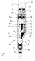
- the branch sleeve 1 shown as an example in the figure has an approximately T-shaped one Branch part 3, which is designed, for example, with three as a socket Plug devices 5 and 6 is provided.
- the two plug devices 5 are in this Embodiment in a line along the branch sleeve 1.
- the third connector 6 is parallel and offset to the two connectors 5 in an angled Area 7 of the branch part 3 is formed.
- the branch sleeve 1 shown here the especially suitable for single-line plastic or medium voltage cables, serves to establish an electrical connection between an electrical conductor 9 a main cable 11 and an electrical conductor 13 of a branch cable 15.
- the end of the electrical conductor 13 of the branch cable 15 is for example by means of a Figure shown insoluble pressing or by means of a screw with a provided electrical connector 17, the z. B. in the angled area 7 of the Branch part 3 provided connector 6 and inserted by means of a Branch part 3 arranged locking connection in its position opposite the branch part is set.
- the electrical contact between connector 17 and branch part 3 is e.g. B. by means of known contact elements arranged in the plug device 6 ensured.
- the main cable 11 is severed in the illustrated embodiment.
- E.g. likewise by means of an insoluble pressing shown in the figure or by means of a Screw connection is a plug connector 19 at each of the two ends of the main cable 11 or 21 mounted.
- the two connectors 19 and 21 are, for example, in one Line connectors 5 of the branch part 3 are inserted and are in their position fixed for example by means of a latching connection provided in the branch part.
- the Fixing the connectors 17, 19 and 21 ensures a safe electrical Contact to branch part 3 and via this between main cable 11 and branch cable 15.
- the branch part 3 is enclosed by a sleeve body 25 which extends over the Branch part 3 and the sections of the ends of the Main cable 11 and the branch cable 15 extends away.
- the sleeve body 25 is, for. B. designed as a prefabricated slide-on part made of an elastic material such as silicone, so that the sleeve body due to its high elasticity and diameter tolerances Diameter changes of main cable 11 and branch cable 15 due to load changes can easily record. But it is also possible to the sleeve body 25 as Form cold shrink part.
- the Socket body 25 of the exemplary embodiment includes a branch part 3, electrically conductive field control element 27 integrated.
- the sleeve body 25 also has three cable bushings 29 for passing the two ends of the main cable 11 and the end of the branch cable 15. In order to break down too strong Enabling field strength concentrations in the area of these cable ends are in the area the cable bushings 29 with the respective shield of the main cable 11 or Branch cable 15 connected, electrically conductive field control elements 33 intended.
- the field control elements 27 and 33 are also elastic and in the Socket body 25 firmly cast.
- a braided hose 37, the z. B. is made of copper, connects the electrical Screen 39 of the two ends of the main cable 11 with each other and with the electrical Shield 41 of the branch cable 15.
- the braided hose 37 z. B. by means of a Press connector 43 with the shield wires of the shield 39 of the main cable 11 and Shield wires of the shield 41 of the branch cable 15 connected.
- a screw connector instead of the press connector 43.
- On the other side of the branch sleeve 1 is the single end of the main cable 11 z. B. means a contact roll spring 45 connected to the braided hose 37.
- a sealing clip is arranged on both cable ends. But it is also possible at this point a so-called two-finger split shrink cap use.
Landscapes
- Cable Accessories (AREA)
Applications Claiming Priority (2)
| Application Number | Priority Date | Filing Date | Title |
|---|---|---|---|
| DE19733853A DE19733853A1 (de) | 1997-08-05 | 1997-08-05 | Abzweigmuffe für elektrische Kabel |
| DE19733853 | 1997-08-05 |
Publications (2)
| Publication Number | Publication Date |
|---|---|
| EP0896409A2 true EP0896409A2 (fr) | 1999-02-10 |
| EP0896409A3 EP0896409A3 (fr) | 1999-12-15 |
Family
ID=7838056
Family Applications (1)
| Application Number | Title | Priority Date | Filing Date |
|---|---|---|---|
| EP98401776A Withdrawn EP0896409A3 (fr) | 1997-08-05 | 1998-07-13 | Dérivation pour câble d'énergie |
Country Status (2)
| Country | Link |
|---|---|
| EP (1) | EP0896409A3 (fr) |
| DE (1) | DE19733853A1 (fr) |
Cited By (3)
| Publication number | Priority date | Publication date | Assignee | Title |
|---|---|---|---|---|
| WO2014070851A1 (fr) | 2012-10-31 | 2014-05-08 | Delphi Technologies, Inc. | Dispositif et procédé de raccordement de câbles de fil blindés |
| EP3526868A1 (fr) * | 2016-10-14 | 2019-08-21 | Supergrid Institute | Systeme sous-marin de raccordement electrique |
| EP4049898A1 (fr) * | 2021-02-25 | 2022-08-31 | LEONI Bordnetz-Systeme GmbH | Ensemble de câbles, ainsi que procédé de conception d'un ensemble de câbles |
Families Citing this family (2)
| Publication number | Priority date | Publication date | Assignee | Title |
|---|---|---|---|---|
| DE102013011874A1 (de) | 2013-07-17 | 2015-01-22 | Leoni Bordnetz-Systeme Gmbh | Elektrischer Leistungsverteiler für ein Elektro- oder Hybridfahrzeug sowie Verteilergehäuse für einen derartigen Leistungsverteiler |
| DE102014008536A1 (de) * | 2014-06-16 | 2015-12-17 | Rwe Deutschland Ag | Elektrische Hausanschlussleitung |
Family Cites Families (12)
| Publication number | Priority date | Publication date | Assignee | Title |
|---|---|---|---|---|
| DE3308225A1 (de) * | 1983-03-04 | 1984-09-06 | Siemens AG, 1000 Berlin und 8000 München | Vorgefertigte verbindungsmuffe mit leitersteckverbindung |
| DE3508329A1 (de) * | 1985-03-06 | 1986-09-11 | Siemens AG, 1000 Berlin und 8000 München | Steckbare kabelgarnitur |
| DE8804221U1 (de) * | 1988-03-29 | 1988-05-11 | Felten & Guilleaume Energietechnik AG, 5000 Köln | Aufschiebbare Reparaturmuffe für Kunststoffisolierte Kabel |
| NL8901138A (nl) * | 1989-05-03 | 1990-12-03 | Nkf Kabel Bv | Insteekverbinding voor hoogspanningskunststofkabels. |
| JPH05219638A (ja) * | 1992-02-05 | 1993-08-27 | Reiji Nakamura | 高圧電線の分岐接続装置 |
| JPH05244715A (ja) * | 1992-02-26 | 1993-09-21 | Showa Electric Wire & Cable Co Ltd | ケーブルの分岐接続部 |
| DE9217344U1 (de) * | 1992-12-18 | 1993-02-18 | Mannesmann Kienzle GmbH, 7730 Villingen-Schwenningen | Abzweigverbindung für elektrische Leitungen |
| GB9300728D0 (en) * | 1993-01-15 | 1993-03-03 | Raychem Gmbh | Cable joint |
| DE9300775U1 (de) * | 1993-01-21 | 1993-04-22 | August Rich. Dietz u. Sohn Draht- und Hanfseilwerk GmbH & Co. KG, 8632 Neustadt | Verbindungshalterung mit Anschlüssen für ummantelte Seile bei Gleisstromkreisen |
| JPH06327133A (ja) * | 1993-05-14 | 1994-11-25 | Showa Electric Wire & Cable Co Ltd | 分岐接続部 |
| JP3139251B2 (ja) * | 1993-11-29 | 2001-02-26 | 日立電線株式会社 | 分岐付ケーブル |
| JPH0865874A (ja) * | 1994-08-15 | 1996-03-08 | Hitachi Cable Ltd | 高圧耐火ケーブル接続部 |
-
1997
- 1997-08-05 DE DE19733853A patent/DE19733853A1/de not_active Withdrawn
-
1998
- 1998-07-13 EP EP98401776A patent/EP0896409A3/fr not_active Withdrawn
Cited By (6)
| Publication number | Priority date | Publication date | Assignee | Title |
|---|---|---|---|---|
| WO2014070851A1 (fr) | 2012-10-31 | 2014-05-08 | Delphi Technologies, Inc. | Dispositif et procédé de raccordement de câbles de fil blindés |
| EP2915171A4 (fr) * | 2012-10-31 | 2016-07-13 | Delphi Tech Inc | Dispositif et procédé de raccordement de câbles de fil blindés |
| US9917434B2 (en) | 2012-10-31 | 2018-03-13 | Delphi Technologies, Inc. | Device and method for splicing shielded wire cables |
| EP3526868A1 (fr) * | 2016-10-14 | 2019-08-21 | Supergrid Institute | Systeme sous-marin de raccordement electrique |
| US10756529B2 (en) | 2016-10-14 | 2020-08-25 | Supergrid Institute | Underwater electrical connection system |
| EP4049898A1 (fr) * | 2021-02-25 | 2022-08-31 | LEONI Bordnetz-Systeme GmbH | Ensemble de câbles, ainsi que procédé de conception d'un ensemble de câbles |
Also Published As
| Publication number | Publication date |
|---|---|
| DE19733853A1 (de) | 1999-02-11 |
| EP0896409A3 (fr) | 1999-12-15 |
Similar Documents
| Publication | Publication Date | Title |
|---|---|---|
| DE69704866T2 (de) | Elektrischer verbinder | |
| DE69400313T3 (de) | Verbinder für übertragungsleitung und zusammenbau desselben | |
| DE2132418C2 (de) | Kabelverbinder für Hochspannungskabel | |
| DE69700498T2 (de) | Abzweigverbinder für erdkabel | |
| DE202017101060U1 (de) | Steckverbinder, insbesondere für eine Hochstromanwendung | |
| WO2019057239A1 (fr) | Connecteur pour courants forts muni d'une douille isolante | |
| EP0691721B1 (fr) | Terminaison de connecteur | |
| DE3301362A1 (de) | Kabelverteiler, bzw. -abzweiger | |
| DE1765120A1 (de) | Anschlussstueck fuer elektrische Leiter | |
| EP0818075A1 (fr) | Detecteurs d'arcs accidentels se produisant dans des installations de commutation utilisees pour la distribution d'energie electrique | |
| EP0919076A1 (fr) | Installation a haute tension isolee par gas, encapsulee et pourvue d'un composant de connexion cloisonne | |
| DE69022071T2 (de) | Kabelverbinder. | |
| EP0896409A2 (fr) | Dérivation pour câble d'énergie | |
| EP0773601A2 (fr) | Connexion enfichable de sécurité | |
| EP2175532A2 (fr) | Liaison d'une pièce en aluminium et d'une pièce en cuivre | |
| DE102007013332B4 (de) | Vorrichtung zur Bildung einer Umhüllung insbesondere für eine Verbindungsstelle zwischen zwei geschirmten Kabeln sowie Kabelanordnung mit solchen Kabeln | |
| DE3042595C2 (de) | Aufschiebbare, mit geteiltem Isolierkörper versehene Verbindungsmuffe für kunststoffisolierte Mittelspannungskabel | |
| DE10022547C2 (de) | Kabelanschluß- oder -verbindungseinrichtung | |
| DE102013016099A1 (de) | Mehrfachanschlusskabel zur Verbindung von Hochspannungsvorrichtungen eines Kraftfahrzeugs und Kraftfahrzeug | |
| DE102023209887B4 (de) | Kontaktanbindung für eine elektrische Leitung | |
| DE3914978A1 (de) | Lichtwellenleiter-steckverbindung | |
| EP0769795A2 (fr) | Fusible de haute puissance haute tension pour une ligne de connexion électrique | |
| DE3301361A1 (de) | Kabelverteiler, bzw. -abzweiger | |
| DE3304145C2 (de) | Kabelabschluß oder -verbindung | |
| DE102018116399A1 (de) | Verbindungsmuffe |
Legal Events
| Date | Code | Title | Description |
|---|---|---|---|
| PUAI | Public reference made under article 153(3) epc to a published international application that has entered the european phase |
Free format text: ORIGINAL CODE: 0009012 |
|
| AK | Designated contracting states |
Kind code of ref document: A2 Designated state(s): AT BE CH DE ES FR GB IT LI NL SE |
|
| AX | Request for extension of the european patent |
Free format text: AL;LT;LV;MK;RO;SI |
|
| PUAL | Search report despatched |
Free format text: ORIGINAL CODE: 0009013 |
|
| AK | Designated contracting states |
Kind code of ref document: A3 Designated state(s): AT BE CH CY DE DK ES FI FR GB GR IE IT LI LU MC NL PT SE |
|
| AX | Request for extension of the european patent |
Free format text: AL;LT;LV;MK;RO;SI |
|
| 17P | Request for examination filed |
Effective date: 19991113 |
|
| 17Q | First examination report despatched |
Effective date: 20000313 |
|
| AKX | Designation fees paid | ||
| REG | Reference to a national code |
Ref country code: DE Ref legal event code: 8566 |
|
| RBV | Designated contracting states (corrected) |
Designated state(s): AT BE CH DE ES FR GB IT LI NL SE |
|
| RAP1 | Party data changed (applicant data changed or rights of an application transferred) |
Owner name: NEXANS |
|
| STAA | Information on the status of an ep patent application or granted ep patent |
Free format text: STATUS: THE APPLICATION IS DEEMED TO BE WITHDRAWN |
|
| 18D | Application deemed to be withdrawn |
Effective date: 20010717 |