EP0896834A2 - Dispersing apparatus for complete wetting of single particle powder materials - Google Patents
Dispersing apparatus for complete wetting of single particle powder materials Download PDFInfo
- Publication number
- EP0896834A2 EP0896834A2 EP98115120A EP98115120A EP0896834A2 EP 0896834 A2 EP0896834 A2 EP 0896834A2 EP 98115120 A EP98115120 A EP 98115120A EP 98115120 A EP98115120 A EP 98115120A EP 0896834 A2 EP0896834 A2 EP 0896834A2
- Authority
- EP
- European Patent Office
- Prior art keywords
- dispersing
- disks
- shaft
- connecting webs
- dispersing device
- Prior art date
- Legal status (The legal status is an assumption and is not a legal conclusion. Google has not performed a legal analysis and makes no representation as to the accuracy of the status listed.)
- Granted
Links
Images

Classifications
-
- B—PERFORMING OPERATIONS; TRANSPORTING
- B01—PHYSICAL OR CHEMICAL PROCESSES OR APPARATUS IN GENERAL
- B01F—MIXING, e.g. DISSOLVING, EMULSIFYING OR DISPERSING
- B01F23/00—Mixing according to the phases to be mixed, e.g. dispersing or emulsifying
- B01F23/50—Mixing liquids with solids
- B01F23/56—Mixing liquids with solids by introducing solids in liquids, e.g. dispersing or dissolving
-
- B—PERFORMING OPERATIONS; TRANSPORTING
- B01—PHYSICAL OR CHEMICAL PROCESSES OR APPARATUS IN GENERAL
- B01F—MIXING, e.g. DISSOLVING, EMULSIFYING OR DISPERSING
- B01F27/00—Mixers with rotary stirring devices in fixed receptacles; Kneaders
- B01F27/05—Stirrers
- B01F27/11—Stirrers characterised by the configuration of the stirrers
- B01F27/115—Stirrers characterised by the configuration of the stirrers comprising discs or disc-like elements essentially perpendicular to the stirrer shaft axis
-
- B—PERFORMING OPERATIONS; TRANSPORTING
- B01—PHYSICAL OR CHEMICAL PROCESSES OR APPARATUS IN GENERAL
- B01F—MIXING, e.g. DISSOLVING, EMULSIFYING OR DISPERSING
- B01F27/00—Mixers with rotary stirring devices in fixed receptacles; Kneaders
- B01F27/80—Mixers with rotary stirring devices in fixed receptacles; Kneaders with stirrers rotating about a substantially vertical axis
- B01F27/93—Mixers with rotary stirring devices in fixed receptacles; Kneaders with stirrers rotating about a substantially vertical axis with rotary discs
-
- B—PERFORMING OPERATIONS; TRANSPORTING
- B01—PHYSICAL OR CHEMICAL PROCESSES OR APPARATUS IN GENERAL
- B01F—MIXING, e.g. DISSOLVING, EMULSIFYING OR DISPERSING
- B01F27/00—Mixers with rotary stirring devices in fixed receptacles; Kneaders
- B01F27/05—Stirrers
- B01F27/11—Stirrers characterised by the configuration of the stirrers
- B01F27/19—Stirrers with two or more mixing elements mounted in sequence on the same axis
- B01F27/191—Stirrers with two or more mixing elements mounted in sequence on the same axis with similar elements
Definitions
- the invention relates to a dispersing device for all-round wetting of primary particles, such as powdery Substances, color pigments, fillers and the like at least two dispersing disks arranged parallel to each other, at least one with one Dispersion shaft is connected with teeth that are radial are arranged on the outside of the dispersing disks, and with connecting webs that space the dispersing disks hold.
- primary particles such as powdery Substances, color pigments, fillers and the like
- Dispersion shaft is connected with teeth that are radial are arranged on the outside of the dispersing disks, and with connecting webs that space the dispersing disks hold.
- dispersing devices - also dispersing tools called - are each at the end of a vertical in arranged the dispersing wave submerged.
- dispersing means that all-round wetting of primary particles of powdery substances, such as B. color pigments, fillers and the like, which is usually when pouring into the liquid Form agglomerates.
- Dispersing in the form described above, differs different from a lot in chemistry occurring simple stirring process, in which often only Liquids with each other or liquids with little Proportion of powdery substances mixed or getting produced.
- an agitator is known preferably a circular head disc and one preferably has circular base, between which an intermediate plate in the middle perpendicular to the panes is arranged.
- DE 34 38 766 A1 discloses a dispersing device known with a driven driven around its central axis Deflector consisting of a rotating shaft and a arranged in the region of the lower end of the rotary shaft There is a rotor disk, with the disk plane opposite the axis of the rotary shaft is inclined and at least one Has passage opening.
- a mixer head piece is known from DE 26 44 326 A1, that consists of two coaxially one above the other Discs exist between which knives are arranged are.
- the disks have essentially radial Slits on the rear edge of a leg arranged with right-angled knives is.
- a stirring tool is known from DE-OS 18 14 506, the one at the end of a spindle arranged stirring head has, which consists of several annular stirring disks exists, which are kept at a distance by spacers and are pressed together by screws.
- a mixing tool is known from US 44 51 155 the shaft of which several parallel ring-shaped stirring disks are attached, some of which have an internal opening for sucking in the mix.
- the relationship of the diameter of the stirring disks to the total height the mixing tool is 8: 1.
- a stirring device which consists of two parallel stirring discs.
- the agitator discs have baffles on both sides on the mix through in the direction of rotation bores arranged in front of the baffle plates should press.
- a stirring device is known from US 30 30 083, which consists of two parallel stirring disks, which have suction holes. Furthermore, the Stirring baffles arranged.
- a stirring device which consists of two parallel stirring disks, the ends of which have teeth. Furthermore, the Stirring discs arranged suction holes.
- a stirring device which has two disks arranged on a shaft, the in the direction of rotation alternately different from the plane of rotation has extending surface areas. Further the device is provided with teeth.
- mixing devices are generally known where the stirring disks are held together by a basket are connected, in which two axially arranged to each other Flanges as a mounting base for the Stirring discs serve and the flanges are fixed by webs are interconnected.
- the flanges obstruct the flow and prevent the flow Bridges must be chosen accordingly long in the Rule 150-200mm. This means that one for one optimal dispersion process necessary low Fill level in the mixing container only one, namely the lower one Toothed lock washer, immersed.
- the object of the present invention is a device to create that at different times often low filling levels has better dispersing properties.
- the generated by the disks laminar flow even when adding powdery Fabrics are maintained.
- the connecting webs additionally at least one flattened Side edge and are in their radial arrangement at an oblique angle to the in the Dispersion disks with centric shaft bores aligned.
- Test series with the invention Device have especially in difficult to wet powdery solids a reduction in die time to 1/3 of the usual time.
- suction openings points exclusively the upper dispersion disc, next to that for the pump effect important shaft bore, suction openings on. These suction openings are radial on the dispersing disc arranged and improve the promotion of the dispersing product. The dispersion time is thus reduces what a low heat load on the mix brings with it.
- the dispersing disks have different tooth shapes and / or different Diameter.
- the multiple disk 10 shown in FIG. 1 exists essentially, as shown in Figure 3, from a upper dispersing disc 11 and a lower dispersing disc 12 that are parallel to each other and coaxial to a dispersing shaft 14 are arranged.
- the dispersing disks 11 and 12 are through connecting webs 15 connected with each other.
- the dispersing disks 11 and 12 are at a uniform distance 30 from each other held and aligned.
- the connecting webs 15 are preferably rectangular, whereby the Side surfaces 39 are large.
- This geometric Form represents a sufficiently large and stable forehead and Support surface 37 for the dispersing disks 11, 12 and 12a ready. Oval shapes of the connecting webs 15 are also conceivable, since they also have flat surfaces exhibit.
- the upper dispersion disk 11 is arranged concentrically Provided suction openings 20, while the lower Dispersion disc 12 is closed.
- a multiple disc 10a is shown at which also includes the lower dispersing disc 12a with suction openings 21 is equipped.
- the dispersing disks 11, 12 and 12a have on their External circumferences teeth 16, 17 and 18, respectively, which are laminar Generate flow. Especially from the figures 3 and 5 it can be seen that the teeth 16, 17 and 18th with different setting angles 28 upwards and below from the plane of the dispersing disks 11, 12 and 12a are bounded.
- FIG. 3 shows an embodiment in which two different setting angles 28 are provided, whereby every second tooth 16 or 17 is equally set is.
- FIG. 5 shows an embodiment, in which every third tooth 16 or 17 or 18 is immediately restricted.
- the connecting webs 15 are by releasable connecting means 19 with the dispersing disks 11, 12 and 12a connected. As FIG. 2 shows in detail, these are Lanyard 19 screws in thread 29 in screwed the end faces 37 of the connecting webs 15 can be.
- the connecting webs 15 extend from the top of the dispersing disk 25 of the lower dispersing disc 12 to the underside of the dispersion disk 26 of the upper one Dispersing disc 11.
- the connecting webs 15 are concentric to the dispersing shaft 14 on the dispersing disks 11, 12 and 12a attached. Due to the lack of Mounting flanges, corresponds to the length of the connecting webs 15 essentially the distance 30 between the upper dispersing disk 11 and the lower dispersing disk 12 or 12a.
- the outer diameter 31 of the Dispersion disks 11, 12 and 12a are approximately five up to twenty times greater than the length 30 of the connecting webs 15 corresponds to.
- the connecting webs 15 a flattened side edge 24, the preferably facing the direction of rotation 38 (arrow) is. This will cause uncontrolled eddies in front of those caused by the rotating movement with dispersed material avoided sides.
- Other known aerodynamic Shapes of the connecting webs 15 are also conceivable insofar as they control the direction of flow influence.
- the connecting webs are 15 in a predetermined angle of attack 27 against one passing through the center 36 of the dispersing shaft 14 Radials 32 aligned.
- the angle of attack 27 the connecting webs are 15 smaller than 90 °, preferably 70 ° to 85 ° are provided.
- the releasable connecting means 19 make it possible to one of a multitude of connecting bridges of the same length 15 existing connecting web set against one exchange others, the longer or shorter ones Connecting webs 15 exist. This allows the distance 30 between the dispersing disks 11, 12 and 12a be set differently as required. It there is also the possibility of dispersing disks with different diameters and / or with different To combine teeth.
- the upper dispersing disc 11 has a central one Shaft bore 22 and the lower dispersing disk 12 or 12a has a central shaft bore 23, through which the dispersing shaft 14 is guided.
- the dispersion wave 14 is preferably a - not shown - Gear and by a - not shown Motor started to rotate. Especially in dispersion applications is a stepless regulation of the engine or the gearbox important for optimal dispersion results to reach.
- the shaft bore 22 of the upper dispersion disk 11 has a larger inner diameter 33 than that corresponds to the outer diameter 35 of the dispersing shaft 14.
- the dispersing shaft 14 is therefore contact-free passed through the upper dispersing disk 11.
- At the rotation of the multiple disc 10 or 10a arises such a suction through the shaft bore 22, which is a laminar Flow generated.
- the laminar flow extends through the shaft bore 22 here further to the radially outer Edge area of the multiple pane 10 or 10a.
- the inside diameter 33 not with the dispersing shaft 14 connected shaft bore 22 of the upper dispersion disk 11 is larger than the inner diameter 34 of the shaft bore 23 connected to the dispersing shaft 14 the lower dispersing disk 12 or 12a.
- the shaft bore 23 of the lower dispersing disk 12 or 12a corresponds approximately to the outer diameter 35 of the dispersing shaft 14.
- the dispersing disks 11, 12 and 12a have the same Outside diameter 31. In another version have the dispersing disks 11, 12 and 12a different Outside diameter 31.
- the dispersing disks have 11 and 12a suction openings 20 and 21, which are arranged concentrically spaced from the dispersing shaft 14 are.
- the lower dispersing disks are 12 and 12a in their central shaft bores 23 via fastening means 13 with the lower one free end of the dispersing shaft 14 connected.
- the inside diameter 34 of the shaft bores 23 correspond essentially the outer diameter 35 of the dispersing shaft 14.
Landscapes
- Chemical & Material Sciences (AREA)
- Chemical Kinetics & Catalysis (AREA)
- Dispersion Chemistry (AREA)
- Mixers Of The Rotary Stirring Type (AREA)
- Pigments, Carbon Blacks, Or Wood Stains (AREA)
- Coloring (AREA)
- Mechanical Treatment Of Semiconductor (AREA)
- Physical Or Chemical Processes And Apparatus (AREA)
Abstract
Description
Die Erfindung betrifft eine Dispergiervorrichtung zum allseitigen Benetzen von Primärteilchen, wie pulverigen Stoffen, Farbpigmenten, Füllstoffen und dergleichen mit mindestens zwei parallel zueinander angeordneten Dispergierscheiben, von denen mindestens eine mit einer Dispergierwelle verbunden ist, mit Zähnen, die radial außen an den Dispergierscheiben angeordnet sind, und mit Verbindungsstegen, die die Dispergierscheiben beabstandet halten.The invention relates to a dispersing device for all-round wetting of primary particles, such as powdery Substances, color pigments, fillers and the like at least two dispersing disks arranged parallel to each other, at least one with one Dispersion shaft is connected with teeth that are radial are arranged on the outside of the dispersing disks, and with connecting webs that space the dispersing disks hold.
Diese Dispergiervorrichtungen - auch Dispergierwerkzeuge genannt - sind jeweils am Ende einer senkrecht in das Mischgut tauchenden Dispergierwelle angeordnet. Unter Dispergieren versteht man im vorliegenden Falle das allseitige Benetzen von Primärteilchen pulveriger Stoffe, wie z. B. Farbpigmente, Füllstoffe und dergleichen, die in der Regel beim Einschütten in die Flüssigkeit Agglomerate bilden. These dispersing devices - also dispersing tools called - are each at the end of a vertical in arranged the dispersing wave submerged. Under In the present case, dispersing means that all-round wetting of primary particles of powdery substances, such as B. color pigments, fillers and the like, which is usually when pouring into the liquid Form agglomerates.
Zur Erreichung einer gleichmäßigen Primärteilchenbenetzung, ist die Übertragung einer hohen Leistung auf das Mischgut erforderlich. Aus diesem Grund muß eine hohe Feststoffkonzentration gewählt werden, um beim Dispergierprozeß ein Verspritzen zu vermeiden. Erst nach Erreichen einer homogenen Benetzung darf auf die Gebrauchskonsistenz verdünnt werden. Hierdurch wird verständlicherweise das Benetzen der pulverigen Stoffe, die oftmals verschiedener Art und Dichte sind, problematisch und zeitaufwendig.To achieve uniform primary particle wetting, is the transfer of high power to that Mix required. For this reason, a high Solid concentration can be chosen to be used in the dispersion process to avoid splashing. Only after reaching homogeneous wetting may affect the consistency of use be diluted. This will understandably wetting the powdery substances, which are often of different types and densities are problematic and time consuming.
Dispergieren, in der vorher beschriebenen Form, unterscheidet sich stark von einem vielfach in der Chemie vorkommenden einfachen Rührvorgang, bei dem oftmals nur Flüssigkeiten untereinander oder Flüssigkeiten mit geringem Anteil von pulverigen Stoffen vermischt oder hergestellt werden.Dispersing, in the form described above, differs different from a lot in chemistry occurring simple stirring process, in which often only Liquids with each other or liquids with little Proportion of powdery substances mixed or getting produced.
Aus der DE 36 16 203 A1 ist ein Rührwerk bekannt, das vorzugsweise eine kreisrunde Kopfscheibe und eine vorzugsweise kreisrunde Fußscheibe aufweist, zwischen denen mittig senkrecht zu den Scheiben eine Zwischenplatte angeordnet ist.From DE 36 16 203 A1 an agitator is known preferably a circular head disc and one preferably has circular base, between which an intermediate plate in the middle perpendicular to the panes is arranged.
Aus der DE 34 38 766 A1 ist eine Dispergiervorrichtung bekannt mit einem um seine Mittelachse drehbaren, angetriebenen Umlenker, der aus einer Drehwelle und einer im Bereich des unteren Endes der Drehwelle angeordneten Rotorscheibe besteht, wobei die Scheibenebene gegenüber der Achse der Drehwelle geneigt ist und wenigstens eine Durchtrittsöffnung aufweist.DE 34 38 766 A1 discloses a dispersing device known with a driven driven around its central axis Deflector consisting of a rotating shaft and a arranged in the region of the lower end of the rotary shaft There is a rotor disk, with the disk plane opposite the axis of the rotary shaft is inclined and at least one Has passage opening.
Aus der DE 26 44 326 A1 ist ein Mischerkopfstück bekannt, das aus zwei koaxial übereinander liegenden Scheiben besteht, zwischen denen Messer angeordnet sind. Die Scheiben weisen im wesentlichen radial verlaufende Schlitze auf, an deren Hinterkante ein Schenkel mit rechtwinklig ausgebildeten Messern angeordnet ist.A mixer head piece is known from DE 26 44 326 A1, that consists of two coaxially one above the other Discs exist between which knives are arranged are. The disks have essentially radial Slits on the rear edge of a leg arranged with right-angled knives is.
Aus der DE 1 941 831 PS ist ein Werkzeug bekannt, das an einem Ende an einer Antriebswelle befestigt ist, das eine Scheibe aufweist, auf deren Oberfläche radial verlaufende Flügel befestigt sind, deren Oberseiten mit einem Kranz befestigt sind.From DE 1 941 831 PS a tool is known that is attached at one end to a drive shaft, the has a disc on the surface of which extends radially Wings are attached, the tops of which are are attached to a wreath.
Aus der DE-OS 18 14 506 ist ein Rührwerkzeug bekannt, das einen am Ende einer Spindel angeordneten Rührkopf aufweist, der aus mehreren ringförmigen Rührscheiben besteht, die durch Distanzschelben auf Abstand gehalten sind und durch Schrauben zusammengedrückt werden.A stirring tool is known from DE-OS 18 14 506, the one at the end of a spindle arranged stirring head has, which consists of several annular stirring disks exists, which are kept at a distance by spacers and are pressed together by screws.
Aus der US 44 51 155 ist ein Mischwerkzeug bekannt, an dessen Welle mehrere parallele ringförmige Rührscheiben befestigt sind, von denen einige eine innere Öffnung zum Ansaugen der Mischgutes aufweisen. Das Verhältnis des Durchmessers der Rührscheiben zu der gesamten Höhe des Rührwerkzeuges beträgt 8:1.A mixing tool is known from US 44 51 155 the shaft of which several parallel ring-shaped stirring disks are attached, some of which have an internal opening for sucking in the mix. The relationship of the diameter of the stirring disks to the total height the mixing tool is 8: 1.
Aus der DE 82 34 623 U1 ist eine Rührvorrichtung zum Mischen von Stoffen bekannt, bei der zwischen zwei im Abstand angeordneten koaxialen Scheiben, die mit Durchgangsöffnungen versehen sind, Rührscheiben angeordnet sind. Durch Anbringen von weiteren Rührscheiben auf den Außenseiten der Scheiben soll die Mischwirkung verbessert werden.From DE 82 34 623 U1 a stirring device for Mixing substances known between two in the Spaced coaxial disks with through holes are provided, stirring disks arranged are. By attaching additional stirring disks to the The mixing effect is improved on the outside of the disks become.
Aus der US 36 30 636 ist eine Rührvorrichtung bekannt, die aus zwei parallel angeordneten Rührscheiben besteht. Die Rührscheiben weisen auf beiden Seiten Ablenkbleche auf, die das Mischgut durch in Rotationsrichtung vor den Ablenkblechen angeordneten Bohrungen drücken sollen. From US 36 30 636 a stirring device is known which consists of two parallel stirring discs. The agitator discs have baffles on both sides on the mix through in the direction of rotation bores arranged in front of the baffle plates should press.
Aus der US 30 30 083 ist eine Rührvorrichtung bekannt, die aus zwei parallel angeordneten Rührscheiben besteht, die Saugbohrungen aufweisen. Ferner sind auf den Rührscheiben Ablenkbleche angeordnet.A stirring device is known from US 30 30 083, which consists of two parallel stirring disks, which have suction holes. Furthermore, the Stirring baffles arranged.
Aus der US 48 13 787 ist eine Rührvorrichtung bekannt, die aus zwei parallel angeordneten Rührscheiben besteht, deren Enden Zähne aufweisen. Ferner sind auf den Rührscheiben Saugbohrungen angeordnet.From US 48 13 787 a stirring device is known which consists of two parallel stirring disks, the ends of which have teeth. Furthermore, the Stirring discs arranged suction holes.
Aus der DD 42 040 ist eine Rührvorrichtung bekannt, die zwei auf einer Welle angeordnete Scheiben aufweist, die in Umlaufrichtung abwechselnd verschieden gegen die Rotationsebene verlaufende Flächenbereiche aufweist. Ferner ist die Vorrichtung mit Zähnen versehen.From DD 42 040 a stirring device is known which has two disks arranged on a shaft, the in the direction of rotation alternately different from the plane of rotation has extending surface areas. Further the device is provided with teeth.
Allen diesen Vorrichtung ist gemeinsam, daß sie keine Möglichkeit aufweisen, den Abstand zwischen den Scheiben je nach Bedarf neu festzulegen. Zusätzlich sind die Rührmittel zwischen den Scheiben angeordnet, was eine geringere Effizienz im Vergleich zu einer Anordnung im Randbereich bedeutet.All these devices have in common that they do not Possibility of the distance between the discs redefine as needed. In addition, they are Mixing means arranged between the disks, which is a lower efficiency compared to an arrangement in the Edge area means.
Des weiteren sind Mischvorrichtungen allgemein bekannt, bei denen die Rührscheiben durch einen Korb miteinander verbunden werden, bei denen zwei axial zueinander angeordnete Flansche als Befestigungsgrundlage für die Rührscheiben dienen und die Flansche fest durch Stege miteinander verbunden sind. Bei dieser Vorrichtung sind die Flansche sog- und strömungsbehindernd, wodurch die Stege entsprechend lang gewählt werden müssen, in der Regel 150-200mm. Dies führt dazu, daß bei einem für einen optimalen Dispergierprozeß notwendigen geringen Füllspiegel im Mischbehälter nur eine, nämlich die untere Zahnscheibe, eintaucht. Furthermore, mixing devices are generally known where the stirring disks are held together by a basket are connected, in which two axially arranged to each other Flanges as a mounting base for the Stirring discs serve and the flanges are fixed by webs are interconnected. In this device are the flanges obstruct the flow and prevent the flow Bridges must be chosen accordingly long in the Rule 150-200mm. This means that one for one optimal dispersion process necessary low Fill level in the mixing container only one, namely the lower one Toothed lock washer, immersed.
Aufgabe der vorliegenden Erfindung ist es, eine Vorrichtung zu schaffen, die bei unterschiedlichen oftmals geringen Füllhöhen bessere Dispergiereigenschaften aufweist. Zusätzlich soll die durch die Scheiben erzeugte laminare Strömung auch beim Hinzugeben von pulverigen Stoffen aufrecht erhalten werden.The object of the present invention is a device to create that at different times often low filling levels has better dispersing properties. In addition, the generated by the disks laminar flow even when adding powdery Fabrics are maintained.
Gelöst wird diese Aufgabe durch die Merkmale des Anspruchs
1 insbesondere dadurch, daß die Verbindungsstege
durch lösbare Verbindungsmittel unmittelbar mit den
Dispergierscheiben verbunden sind, wodurch die Verbindungsstege
und / oder die Dispergierscheiben einfach
austauschbar sind, wobei die Seitenflächen der Verbindungsstege
großflächiger ausgebildet sind, um eine ausreichend
große und stabile Stirn- und Auflagefläche für
die Dispergierscheiben bereitzustellen.
Um einen geringeren Strömungswiderstand zu bilden, der die laminare Strömung nicht negativ beeinflußt, weisen die Verbindungsstege zusätzlich mindestens eine abgeflachte Seitenkante auf und sind in ihrer radialen Anordnung in einem schrägen Stellwinkel zu den in den Dispergierscheiben zentrisch ausgebildeten Wellenbohrungen ausgerichtet.To form a lower flow resistance, the that do not negatively affect the laminar flow the connecting webs additionally at least one flattened Side edge and are in their radial arrangement at an oblique angle to the in the Dispersion disks with centric shaft bores aligned.
Beim Dispergieren eines Mischgutes mit geringem Flüssigkeitsanteil, wie z.B. Spachtel, Pasten, Mahlgutansätze, ist es notwendig, mit einem geringen Füllstand im Mischbehälter zu arbeiten, um eine optimale Energieübertragung zu gewährleisten. Damit die erfindungsgemäße Mehrfachscheibe vollständig eintaucht, wird ein entsprechend kurzer Stegsatz gewählt.When dispersing a mix with a low liquid content, such as. Spatulas, pastes, grist batches, it is necessary with a low level work in the mixing tank for optimal energy transfer to ensure. So that the invention If the multiple disc is completely immersed, one becomes corresponding short web set selected.
Ein größerer Abstand der Dispergierscheiben ist hingegen bei der Herstellung von Produkten mit leichten bzw. extrem leichten Füllstoffen - wie z.B. hochdisperser Kieselsäure (auch Aerosil genannt) - notwendig. In diesem Fall ist ein Stegsatz mit einer größeren Länge zu wählen. Versuchsreihen mit der erfindungsgemäßen Vorrichtung haben insbesondere bei schwer zu benetzenden pulverigen Feststoffen eine Dipergierzeitverkürzung auf 1/3 der sonst üblichen Zeit ergeben.However, there is a larger distance between the dispersing disks in the manufacture of products with light or extremely light fillers - such as highly disperse Silica (also called Aerosil) - necessary. In in this case is a web set with a longer length to choose. Test series with the invention Device have especially in difficult to wet powdery solids a reduction in die time to 1/3 of the usual time.
Durch die Verwendung von zwei Dispergierscheiben wird beim Hinzufügen von pulverigen Stoffen nur die laminare Strömung an der Dispergierscheibenoberseite oder im schlechtesten Fall an der oberen Dispergierscheibe unterbrochen. Die Strömung an der unteren Dispergierscheibe wird hingegen aufrecht erhalten. Somit ist ein schnelleres Hinzufügen dieser Stoffe möglich.By using two dispersing disks when adding powdery substances only the laminar ones Flow on the top of the dispersing disc or in worst case interrupted at the upper dispersing disc. The flow at the lower dispersing disc however, is maintained. So is a faster addition of these substances possible.
In einer ersten Ausführungsform weist ausschließlich die obere Dispergierscheibe, neben der für den Pumpeneffekt wichtigen Wellenbohrung, Saugöffnungen auf. Diese Saugöffnungen sind radial auf der Dispergierscheibe angeordnet und verbessern die Förderung, des zu dispergierenden Produkts. Die Dispergierzeit wird somit reduziert, was eine geringe Wärmebelastung des Mischgutes mit sich bringt.In a first embodiment, points exclusively the upper dispersion disc, next to that for the pump effect important shaft bore, suction openings on. These suction openings are radial on the dispersing disc arranged and improve the promotion of the dispersing product. The dispersion time is thus reduces what a low heat load on the mix brings with it.
In einer zweiten Ausführungsform weist sowohl die obere als auch die untere Dispergierscheibe Saugöffnungen auf. In a second embodiment, both the upper as well as the lower dispersing disc suction openings on.
In weiteren Ausführungsformen haben die Dispergierscheiben unterschiedliche Zahnformen und/oder unterschiedliche Durchmesser.In further embodiments, the dispersing disks have different tooth shapes and / or different Diameter.
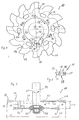
Weitere vorteilhafte Maßnahmen sind in den Unteransprüchen beschrieben. Die Erfindung ist in den beiliegenden Zeichnung dargestellt und wird nachfolgend näher beschrieben; es zeigt:
- Figur 1
- die Draufsicht auf eine Mehrfachscheibe, mit einer oberen und einer unteren Dispergierscheibe, die jeweils eine Wellenbohrung aufweisen, mit Saugöffnungen, die in der oberen Dispergierscheibe angeordnet sind, mit Stegen, die die Dispergierscheiben miteinander verbinden, mit Zähnen zur Erzeugung einer laminaren Strömung;
- Figur 2
- die Detaildarstellung eines Verbindungsstegs
in Draufsicht gemäß Ausschnitt A" in Figur 1, mit einer abgeflachten Seitenkante und Gewinden zur Schraubverbindung mit den Dispergierscheiben;

-
Figur 3 - einen Schnitt entlang der Seitenansicht, mit einer Mehrfachscheibe nach Figur 1, die durch ein Befestigungsmittel an einer Dispergierwelle befestigt ist, wobei die Zähne der Dispergierscheiben versetzt mit einem Abkantwinkel ausgerichtet sind;
- Figur 4
- die Draufsicht auf eine Mehrfachscheibe nach Figur 1, wobei die untere Dispergierscheibe ebenfalls Saugöffnungen aufweist;
- Figur 5
- einen Schnitt entlang der Seitenansicht
nach
Figur 3, wobei die Zähne mit einer Vielzahl von unterschiedlichen Abkantwinkeln versetzt ausgerichtet sind.
- Figure 1
- the top view of a multiple disk, with an upper and a lower dispersing disk, each having a shaft bore, with suction openings which are arranged in the upper dispersing disk, with webs which connect the dispersing disks to one another, with teeth for producing a laminar flow;
- Figure 2
- the detailed view of a connecting web in plan view according to detail A "in Figure 1, with a flattened side edge and threads for screw connection with the dispersing disks;
- Figure 3
- a section along the side view, with a multiple disc according to Figure 1, which is fastened by a fastener to a dispersing shaft, the teeth of the dispersing discs are aligned offset with a folding angle;
- Figure 4
- the top view of a multiple disk according to Figure 1, wherein the lower dispersing disk also has suction openings;
- Figure 5
- a section along the side view of Figure 3, wherein the teeth are aligned offset with a variety of different folding angles.
Die in der Figur 1 dargestellte Mehrfachscheibe 10 besteht
im wesentlichen, wie die Figur 3 zeigt, aus einer
oberen Dispergierscheibe 11 und einer unteren Dispergierscheibe
12, die parallel zueinander und koaxial zu
einer Dispergierwelle 14 angeordnet sind. Die Dispergierscheiben
11 und 12 sind durch Verbindungsstege 15
miteinander verbunden. Die Dispergierscheiben 11 und 12
sind dadurch in einem gleichmäßigen Abstand 30 zueinander
gehalten und ausgerichtet. der Verbindungsstege 15
sind vorzugsweise rechteckig ausgebildet, wodurch die
Seitenflächen 39 großflächiger sind. Diese geometrische
Form stellt eine ausreichend große und stabile Stirn- und
Auflagefläche 37 für die Dispergierscheiben 11, 12
und 12a bereit. Ovale Formen der Verbindungsstege 15
sind ebenfalls denkbar, da auch diese flächige Seiten
aufweisen.The
Die obere Dispergierscheibe 11 ist mit konzentrisch angeordneten
Saugöffnungen 20 versehen, während die untere
Dispergierscheibe 12 geschlossen ist. In den Figuren
4 und 5 ist eine Mehrfachscheibe 10a dargestellt, bei
der auch die untere Dispergierscheibe 12a mit Saugöffnungen
21 ausgestattet ist.The
Die Dispergierscheiben 11, 12 und 12a weisen an ihren
Außenumfängen Zähne 16, 17 bzw. 18 auf, die eine laminare
Strömung erzeugen. Insbesondere aus den Figuren
3 und 5 ist ersichtlich, daß die Zähne 16, 17 und 18
mit unterschiedlichen Schränkungswinkeln 28 nach oben
und unten aus der Ebene der Dispergierscheiben 11, 12
und 12a abgeschränkt sind.The dispersing
Die Figur 3 zeigt eine Ausführungsform, bei der zwei
unterschiedliche Schränkungswinkel 28 vorgesehen sind,
wodurch jeweils jeder zweite Zahn 16 bzw. 17 gleich geschränkt
ist. Figur 5 zeigt hingegen eine Ausführungsform,
bei der jeder dritte Zahn 16 bzw. 17 bzw. 18
gleich geschränkt ist.FIG. 3 shows an embodiment in which two
different setting angles 28 are provided,
whereby every
Die Verbindungsstege 15 sind durch lösbare Verbindungsmittel
19 mit den Dispergierscheiben 11, 12 und 12a
verbunden. Wie die Figur 2 im Detail zeigt, sind die
Verbindungsmittel 19 Schrauben, die in Gewinde 29 in
den Stirnflächen 37 der Verbindungsstege 15 geschraubt
werden können.The connecting
Die Verbindungsstege 15 erstrecken sich von der Dispergierscheibenoberseite
25 der unteren Dispergierscheibe
12 zu der Dispergierscheibenunterseite 26 der oberen
Dispergierscheibe 11. Die Verbindungsstege 15 sind konzentrisch
zu der Dispergierwelle 14 an den Dispergierscheiben
11, 12 und 12a befestigt. Durch das Fehlen von
Befestigungsflanschen, entspricht die Länge der Verbindungsstege
15 im wesentlichen dem Abstand 30 zwischen
der oberen Dispergierscheibe 11 und der unteren Dispergierscheibe
12 bzw. 12a. Die Außendurchmesser 31 der
Dispergierscheiben 11, 12 bzw. 12a sind dabei ca. fünf
bis zwanzigmal größer als es der Länge 30 der Verbindungsstege
15 entspricht.The connecting
Wie die Figuren 1, 2 und 3 zeigen, weisen die Verbindungsstege
15 eine abgeflachte Seitenkante 24 auf, die
vorzugsweise der Rotationsrichtung 38 (Pfeil) zugewandt
ist. Hierdurch werden unkontrollierte Verwirbelungen
vor den durch die Rotationsbewegung mit Dispergiergut
beaufschlagten Seiten vermieden. Andere bekannte strömungsgünstige
Formen der Verbindungsstege 15 sind ebenfalls
denkbar, soweit sie die Strömungsrichtung kontrollierbar
beeinflussen.As shown in Figures 1, 2 and 3, the connecting webs
15 a flattened
Um den Saugeffekt zu verbessern und somit die laminare
Strömung zu erhöhen, sind die Verbindungsstege 15 in
einem vorbestimmten Anstellwinkel 27 gegenüber einer
durch den Mittelpunkt 36 der Dispergierwelle 14 verlaufenden
Radialen 32 ausgerichtet. Die Anstellwinkel 27
der Verbindungsstege sind 15 dabei kleiner 90°, vorzugsweise
sind 70° bis 85° vorgesehen. Bei der Rotationsbewegung
wird hierdurch das - nicht dargestellte -
üblicherweise hochviskose Dispergiergut von den abgeflachten
Seitenkanten 24 der Verbindungsstege 15 von
radial innen nach radial außen gelenkt. Dabei erfolgt
eine innige Benetzung der - nicht dargestellten -
pulverige Primärpartikel, beispielsweise Farbpigmente
und dgl. durch die übelicherweise hochviskose Trägersubstanz,
beispielsweise ein Flüssigharz.To improve the suction effect and thus the laminar
To increase flow, the connecting webs are 15 in
a predetermined angle of attack 27 against one
passing through the
Durch die lösbaren Verbindungsmittel 19 ist es möglich,
einen aus einer Vielzahl von gleich langen Verbindungsstegen
15 bestehenden Verbindungsstegsatz gegen einen
anderen auszutauschen, der aus längeren oder kürzeren
Verbindungsstegen 15 besteht. Hierdurch kann der Abstand
30 zwischen den Dispergierscheiben 11, 12 und 12a
je nach Bedarf unterschiedlich festgelegt werden. Es
ist ebenfalls die Möglichkeit gegeben, Dispergierscheiben
mit unterschiedlichen Durchmesser und/oder mit unterschiedlicher
Zahnung miteinander zu kombinieren.The releasable connecting
Die obere Dispergierscheibe 11 weist eine zentrische
Wellenbohrung 22 und die untere Dispergierscheibe 12
bzw. 12a weist eine zentrische Wellenbohrung 23 auf,
durch die die Dispergierwelle 14 geführt ist. Die Dispergierwelle
14 wird vorzugsweise über ein - nicht dargestelltes
- Getriebe und durch einen - nicht dargestellten
Motor in Rotation versetzt. Speziell bei Dispergieranwendungen
ist eine stufenlose Regelung des Motors
bzw. des Getriebes wichtig, um optimale Dispergierergebnisse
zu erreichen.The
Die Wellenbohrung 22 der oberen Dispergierscheibe 11
weist einen größeren Innendurchmesser 33 auf als er dem
äußeren Durchmesser 35 der Dispergierwelle 14 entspricht.
Die Dispergierwelle 14 ist dadurch berührungsfrei
durch die obere Dispergierscheibe 11 geführt. Bei
der Rotation der Mehrfachscheibe 10 bzw. 10a entsteht
so ein Sog durch die Wellenbohrung 22, der eine laminare
Strömung erzeugt.The shaft bore 22 of the
Die laminare Strömung durch die Wellenbohrung 22 erstreckt
sich hierbei weiter bis zum radial äußeren
Randbereich der Mehrfachscheibe 10 bzw. 10a. Der Innendurchmesser
33 der nicht mit der Dispergierwelle 14
verbundenen Wellenbohrung 22 der oberen Dispergierscheibe
11 ist größer als der Innendurchmesser 34 der
mit der Dispergierwelle 14 verbundenen Wellenbohrung 23
der unteren Dispergierscheibe 12 bzw. 12a. Die Wellenbohrung
23 der unteren Dispergierscheibe 12 bzw. 12a
entspricht etwa dem Außendurchmesser 35 der Dispergierwelle
14.The laminar flow extends through the shaft bore 22
here further to the radially outer
Edge area of the
Die Dispergierscheiben 11, 12 und 12a weisen gleiche
Außendurchmesser 31 auf. Bei einer anderen Ausführung
weisen die Dispergierscheiben 11, 12 und 12a unterschiedliche
Außendurchmesser 31 auf.The dispersing
Um diese Saugwirkung zu steigern, weisen die Dispergierscheiben
11 und 12a Saugöffnungen 20 bzw. 21 auf,
die konzentrisch zur Dispergierwelle 14 beabstandet angeordnet
sind.To increase this suction effect, the dispersing disks have
11 and
Wie die Figuren 3 und 5 zeigen, sind die unteren Dispergierscheiben
12 und 12a in ihren zentrischen Wellenbohrungen
23 über Befestigungsmittel 13 mit dem unteren
freien Ende der Dispergierwelle 14 verbunden. Die Innendurchmesser
34 der Wellenbohrungen 23 entsprechen
dabei im wesentlichen dem Außendurchmesser 35 der Dispergierwelle
14. As FIGS. 3 and 5 show, the lower dispersing disks are
12 and 12a in their central shaft bores
23 via fastening means 13 with the lower one
free end of the dispersing
- 10, 10a10, 10a
- MehrfachscheibeMultiple disc
- 1111
- obere Dispergierscheibeupper dispersing disc
- 12, 12a12, 12a
- untere Dispergierscheibelower dispersing disc
- 1313
- BefestigungsmittelFasteners
- 1414
- DispergierwelleDispersion wave
- 1515
- VerbindungsstegConnecting bridge
- 16, 17, 1816, 17, 18
- Zahntooth
- 1919th
- VerbindungsmittelLanyard
- 20, 2120, 21
- SaugöffnungSuction opening
- 22, 2322, 23
- WellenbohrungShaft drilling
- 2424th
- abgeflachte Seitenkanteflattened side edge
- 2525th
- DispergierscheibenoberseiteDispersion disc top
- 2626
- DispergierscheibenunterseiteDispersing disc underside
- 2727
- AnstellwinkelAngle of attack
- 2828
- SchränkungswinkelHelix angle
- 2929
- Gewindethread
- 3030th
- Abstanddistance
- 3131
- Außendurchmesserouter diameter
- 3232
- RadialeRadial
- 33, 3433, 34
- InnendurchmesserInside diameter
- 3535
- Außendurchmesserouter diameter
- 3636
- MittelpunktFocus
- 3737
- Stirn-/ AuflageflächeFace / support surface
- 3838
- RotationsrichtungDirection of rotation
- 3939
- SeitenflächeSide surface
Claims (16)
Priority Applications (1)
| Application Number | Priority Date | Filing Date | Title |
|---|---|---|---|
| DE29825001U DE29825001U1 (en) | 1997-08-13 | 1998-08-12 | Dispersing apparatus for dispersion of powder into liquid - comprises two-disc rotor assembly which induces laminar flow across discs for even wetting of particles |
Applications Claiming Priority (2)
| Application Number | Priority Date | Filing Date | Title |
|---|---|---|---|
| DE19735000A DE19735000C2 (en) | 1997-08-13 | 1997-08-13 | Dispersing tool for all-round wetting of primary particles of powdery substances |
| DE19735000 | 1997-08-13 |
Publications (3)
| Publication Number | Publication Date |
|---|---|
| EP0896834A2 true EP0896834A2 (en) | 1999-02-17 |
| EP0896834A3 EP0896834A3 (en) | 2001-01-31 |
| EP0896834B1 EP0896834B1 (en) | 2003-11-12 |
Family
ID=7838804
Family Applications (1)
| Application Number | Title | Priority Date | Filing Date |
|---|---|---|---|
| EP98115120A Expired - Lifetime EP0896834B1 (en) | 1997-08-13 | 1998-08-12 | Dispersing apparatus for complete wetting of single particle powder materials |
Country Status (3)
| Country | Link |
|---|---|
| EP (1) | EP0896834B1 (en) |
| AT (1) | ATE253974T1 (en) |
| DE (2) | DE19735000C2 (en) |
Cited By (7)
| Publication number | Priority date | Publication date | Assignee | Title |
|---|---|---|---|---|
| EP1015102A4 (en) * | 1997-08-20 | 2001-02-21 | Tva Technologies Pty Ltd | Improved mixing and aerating apparatus |
| US7473025B1 (en) * | 2008-01-31 | 2009-01-06 | Spx Corporation | Mixing impeller with spiral leading edge |
| EP2659958A1 (en) * | 2012-05-03 | 2013-11-06 | WEPA Apothekenbedarf GmbH & Co.KG | Cogged mixing element |
| CN103391809A (en) * | 2011-03-14 | 2013-11-13 | 德国古斯塔夫·爱立许机械制造有限公司 | Method for granulating or agglomerating and tool therefor |
| JP2014236706A (en) * | 2013-06-10 | 2014-12-18 | レオン自動機株式会社 | Apparatus and method for adhering powder to food product |
| CN111905648A (en) * | 2020-09-21 | 2020-11-10 | 重庆凯茜蔓科技有限公司 | Fine granulating device for water-in-water artistic coating |
| CN113427656A (en) * | 2021-06-29 | 2021-09-24 | 安徽钢腾塑胶模具科技有限公司 | Melting plastic compounding device |
Family Cites Families (13)
| Publication number | Priority date | Publication date | Assignee | Title |
|---|---|---|---|---|
| US2464588A (en) * | 1945-08-03 | 1949-03-15 | Pittsburgh Plate Glass Co | Machine for dispersing agglomerated pigments in liquids |
| US3030083A (en) * | 1959-03-25 | 1962-04-17 | Hugh A Stiffler | Agitator wheel |
| US2984462A (en) * | 1959-09-25 | 1961-05-16 | Donald J O'connor | Mixing device |
| US3071353A (en) * | 1961-03-13 | 1963-01-01 | Klein Sidney | Rotary mixing blade |
| US3486741A (en) * | 1968-02-06 | 1969-12-30 | Ernst L Midgette | Impeller |
| DE1941831B2 (en) * | 1969-08-16 | 1972-03-30 | Eirich, Wilhelm; Eirich, Gustav; 6969 Hardheim | MIXER WITH FORCED-DRIVEN DISC MIXING CONTAINER |
| US3630636A (en) * | 1970-04-22 | 1971-12-28 | Continental Oil Co | Blade apparatus for high-shear mixing |
| US3999889A (en) * | 1975-10-23 | 1976-12-28 | Exxon Research And Engineering Company | Mixing head |
| DE8234623U1 (en) * | 1982-12-09 | 1983-05-05 | EKATO Industrieanlagen Verwaltungsgesellschaft mbH u. Co., 7860 Schopfheim | STIRRING DEVICE |
| US4451155A (en) * | 1983-01-20 | 1984-05-29 | A. R. Wilfley And Sons, Inc. | Mixing device |
| DE3438766A1 (en) * | 1984-10-23 | 1986-04-24 | Lister GmbH Landgeräte- und Kühlanlagenfabrik, 5880 Lüdenscheid | Appliance for producing a vortex movement in a liquid or pasty material |
| DE3616203A1 (en) * | 1986-05-14 | 1987-11-19 | Plasty Spiel Und Sportartikel | Stirrer for paints |
| US4813787A (en) * | 1987-07-23 | 1989-03-21 | Conn Leroy C | Blending apparatus |
-
1997
- 1997-08-13 DE DE19735000A patent/DE19735000C2/en not_active Expired - Fee Related
-
1998
- 1998-08-12 AT AT98115120T patent/ATE253974T1/en not_active IP Right Cessation
- 1998-08-12 EP EP98115120A patent/EP0896834B1/en not_active Expired - Lifetime
- 1998-08-12 DE DE59810132T patent/DE59810132D1/en not_active Expired - Lifetime
Cited By (10)
| Publication number | Priority date | Publication date | Assignee | Title |
|---|---|---|---|---|
| EP1015102A4 (en) * | 1997-08-20 | 2001-02-21 | Tva Technologies Pty Ltd | Improved mixing and aerating apparatus |
| US7473025B1 (en) * | 2008-01-31 | 2009-01-06 | Spx Corporation | Mixing impeller with spiral leading edge |
| AU2009210493B2 (en) * | 2008-01-31 | 2011-08-25 | Spx Flow, Inc. | Mixing impeller with spiral leading edge |
| CN103391809A (en) * | 2011-03-14 | 2013-11-13 | 德国古斯塔夫·爱立许机械制造有限公司 | Method for granulating or agglomerating and tool therefor |
| CN103391809B (en) * | 2011-03-14 | 2016-10-26 | 德国古斯塔夫·爱立许机械制造有限公司 | Method for granulation and agglomeration and tools for the method |
| US11014055B2 (en) | 2011-03-14 | 2021-05-25 | Maschinenfabrik Gustav Eirich Gmbh & Co Kg | Method for granulating or agglomerating and tool therefor |
| EP2659958A1 (en) * | 2012-05-03 | 2013-11-06 | WEPA Apothekenbedarf GmbH & Co.KG | Cogged mixing element |
| JP2014236706A (en) * | 2013-06-10 | 2014-12-18 | レオン自動機株式会社 | Apparatus and method for adhering powder to food product |
| CN111905648A (en) * | 2020-09-21 | 2020-11-10 | 重庆凯茜蔓科技有限公司 | Fine granulating device for water-in-water artistic coating |
| CN113427656A (en) * | 2021-06-29 | 2021-09-24 | 安徽钢腾塑胶模具科技有限公司 | Melting plastic compounding device |
Also Published As
| Publication number | Publication date |
|---|---|
| DE19735000A1 (en) | 1999-02-25 |
| EP0896834A3 (en) | 2001-01-31 |
| DE19735000C2 (en) | 1999-10-21 |
| ATE253974T1 (en) | 2003-11-15 |
| DE59810132D1 (en) | 2003-12-18 |
| EP0896834B1 (en) | 2003-11-12 |
Similar Documents
| Publication | Publication Date | Title |
|---|---|---|
| DE102010008045B4 (en) | Stirring blades and sealed stirring device | |
| EP2659958B1 (en) | Cogged mixing element | |
| DE69015577T2 (en) | Apparatus for the treatment of viscous liquids. | |
| DE602005000098T2 (en) | Dynamic flow mixing device | |
| WO2000021652A1 (en) | Device for mixing two pasty materials, especially for mixing a dental impression material with a catalyst material | |
| DE19947331A1 (en) | Dynamic mixer | |
| EP0063171A2 (en) | Mixing apparatus | |
| EP1471993A1 (en) | Dispersing device | |
| EP1925358B1 (en) | Stirring device for producing a liquid mixture from at least two components, and the use of said stirring device | |
| DE69700463T2 (en) | Stirring lid for paint containers, attached to paint stirrers | |
| DE69630820T2 (en) | MIXER FOR VISCOUS FLUIDE | |
| EP0896834B1 (en) | Dispersing apparatus for complete wetting of single particle powder materials | |
| DE1457270B2 (en) | LIQUID MIXERS | |
| DE202014002901U1 (en) | folding mixer | |
| DE68914629T2 (en) | Crushing, mixing and dispersing device. | |
| DE10354888B4 (en) | Colloidal mixer and process for the colloidal treatment of a mixture | |
| DE4028108C1 (en) | ||
| EP0305576B1 (en) | Stirrer for an industriel mixing machine | |
| DE29825001U1 (en) | Dispersing apparatus for dispersion of powder into liquid - comprises two-disc rotor assembly which induces laminar flow across discs for even wetting of particles | |
| DE3820271A1 (en) | HOMOGENIZING MIXING DEVICE | |
| DE112024001470T5 (en) | Kneading device | |
| EP1106243A2 (en) | Dynamic mixer | |
| DE29724021U1 (en) | Dispersing device for all-round wetting of primary particles of powdery substances | |
| DE10012072A1 (en) | Continually-operated mixer for paste or suspensions has two intermeshing tools rotating on their own individual axes | |
| DE19504033A1 (en) | Agitator disc for mixing e.g. paint with an electric drill |
Legal Events
| Date | Code | Title | Description |
|---|---|---|---|
| PUAI | Public reference made under article 153(3) epc to a published international application that has entered the european phase |
Free format text: ORIGINAL CODE: 0009012 |
|
| AK | Designated contracting states |
Kind code of ref document: A2 Designated state(s): AT BE CH CY DE DK ES FI FR GB GR IE IT LI LU MC NL PT SE |
|
| AX | Request for extension of the european patent |
Free format text: AL;LT;LV;MK;RO;SI |
|
| PUAL | Search report despatched |
Free format text: ORIGINAL CODE: 0009013 |
|
| AK | Designated contracting states |
Kind code of ref document: A3 Designated state(s): AT BE CH CY DE DK ES FI FR GB GR IE IT LI LU MC NL PT SE |
|
| AX | Request for extension of the european patent |
Free format text: AL;LT;LV;MK;RO;SI |
|
| RIC1 | Information provided on ipc code assigned before grant |
Free format text: 7B 01F 7/26 A, 7B 01F 15/00 B |
|
| 17P | Request for examination filed |
Effective date: 20010208 |
|
| AKX | Designation fees paid |
Free format text: AT BE CH CY DE DK ES FI FR GB GR IE IT LI LU MC NL PT SE |
|
| 17Q | First examination report despatched |
Effective date: 20020624 |
|
| GRAH | Despatch of communication of intention to grant a patent |
Free format text: ORIGINAL CODE: EPIDOS IGRA |
|
| GRAS | Grant fee paid |
Free format text: ORIGINAL CODE: EPIDOSNIGR3 |
|
| GRAA | (expected) grant |
Free format text: ORIGINAL CODE: 0009210 |
|
| AK | Designated contracting states |
Kind code of ref document: B1 Designated state(s): AT BE CH CY DE DK ES FI FR GB GR IE IT LI LU MC NL PT SE |
|
| PG25 | Lapsed in a contracting state [announced via postgrant information from national office to epo] |
Ref country code: NL Free format text: LAPSE BECAUSE OF FAILURE TO SUBMIT A TRANSLATION OF THE DESCRIPTION OR TO PAY THE FEE WITHIN THE PRESCRIBED TIME-LIMIT Effective date: 20031112 Ref country code: IT Free format text: LAPSE BECAUSE OF FAILURE TO SUBMIT A TRANSLATION OF THE DESCRIPTION OR TO PAY THE FEE WITHIN THE PRESCRIBED TIME-LIMIT;WARNING: LAPSES OF ITALIAN PATENTS WITH EFFECTIVE DATE BEFORE 2007 MAY HAVE OCCURRED AT ANY TIME BEFORE 2007. THE CORRECT EFFECTIVE DATE MAY BE DIFFERENT FROM THE ONE RECORDED. Effective date: 20031112 Ref country code: IE Free format text: LAPSE BECAUSE OF FAILURE TO SUBMIT A TRANSLATION OF THE DESCRIPTION OR TO PAY THE FEE WITHIN THE PRESCRIBED TIME-LIMIT Effective date: 20031112 Ref country code: GB Free format text: LAPSE BECAUSE OF FAILURE TO SUBMIT A TRANSLATION OF THE DESCRIPTION OR TO PAY THE FEE WITHIN THE PRESCRIBED TIME-LIMIT Effective date: 20031112 Ref country code: FR Free format text: LAPSE BECAUSE OF FAILURE TO SUBMIT A TRANSLATION OF THE DESCRIPTION OR TO PAY THE FEE WITHIN THE PRESCRIBED TIME-LIMIT Effective date: 20031112 Ref country code: FI Free format text: LAPSE BECAUSE OF FAILURE TO SUBMIT A TRANSLATION OF THE DESCRIPTION OR TO PAY THE FEE WITHIN THE PRESCRIBED TIME-LIMIT Effective date: 20031112 Ref country code: CY Free format text: LAPSE BECAUSE OF FAILURE TO SUBMIT A TRANSLATION OF THE DESCRIPTION OR TO PAY THE FEE WITHIN THE PRESCRIBED TIME-LIMIT Effective date: 20031112 |
|
| REG | Reference to a national code |
Ref country code: GB Ref legal event code: FG4D Free format text: NOT ENGLISH |
|
| REG | Reference to a national code |
Ref country code: CH Ref legal event code: EP |
|
| REF | Corresponds to: |
Ref document number: 59810132 Country of ref document: DE Date of ref document: 20031218 Kind code of ref document: P |
|
| REG | Reference to a national code |
Ref country code: IE Ref legal event code: FG4D Free format text: GERMAN |
|
| PG25 | Lapsed in a contracting state [announced via postgrant information from national office to epo] |
Ref country code: SE Free format text: LAPSE BECAUSE OF FAILURE TO SUBMIT A TRANSLATION OF THE DESCRIPTION OR TO PAY THE FEE WITHIN THE PRESCRIBED TIME-LIMIT Effective date: 20040212 Ref country code: GR Free format text: LAPSE BECAUSE OF FAILURE TO SUBMIT A TRANSLATION OF THE DESCRIPTION OR TO PAY THE FEE WITHIN THE PRESCRIBED TIME-LIMIT Effective date: 20040212 Ref country code: DK Free format text: LAPSE BECAUSE OF FAILURE TO SUBMIT A TRANSLATION OF THE DESCRIPTION OR TO PAY THE FEE WITHIN THE PRESCRIBED TIME-LIMIT Effective date: 20040212 |
|
| PG25 | Lapsed in a contracting state [announced via postgrant information from national office to epo] |
Ref country code: ES Free format text: LAPSE BECAUSE OF FAILURE TO SUBMIT A TRANSLATION OF THE DESCRIPTION OR TO PAY THE FEE WITHIN THE PRESCRIBED TIME-LIMIT Effective date: 20040223 |
|
| NLV1 | Nl: lapsed or annulled due to failure to fulfill the requirements of art. 29p and 29m of the patents act | ||
| GBV | Gb: ep patent (uk) treated as always having been void in accordance with gb section 77(7)/1977 [no translation filed] |
Effective date: 20031112 |
|
| REG | Reference to a national code |
Ref country code: IE Ref legal event code: FD4D |
|
| PG25 | Lapsed in a contracting state [announced via postgrant information from national office to epo] |
Ref country code: LU Free format text: LAPSE BECAUSE OF NON-PAYMENT OF DUE FEES Effective date: 20040812 |
|
| PGFP | Annual fee paid to national office [announced via postgrant information from national office to epo] |
Ref country code: CH Payment date: 20040824 Year of fee payment: 7 Ref country code: AT Payment date: 20040824 Year of fee payment: 7 |
|
| PG25 | Lapsed in a contracting state [announced via postgrant information from national office to epo] |
Ref country code: MC Free format text: LAPSE BECAUSE OF NON-PAYMENT OF DUE FEES Effective date: 20040831 Ref country code: BE Free format text: LAPSE BECAUSE OF NON-PAYMENT OF DUE FEES Effective date: 20040831 |
|
| PLBE | No opposition filed within time limit |
Free format text: ORIGINAL CODE: 0009261 |
|
| STAA | Information on the status of an ep patent application or granted ep patent |
Free format text: STATUS: NO OPPOSITION FILED WITHIN TIME LIMIT |
|
| 26N | No opposition filed |
Effective date: 20040813 |
|
| EN | Fr: translation not filed | ||
| BERE | Be: lapsed |
Owner name: WILHELM *NIEMANN G.M.B.H. & CO. K.G. Effective date: 20040831 |
|
| PG25 | Lapsed in a contracting state [announced via postgrant information from national office to epo] |
Ref country code: AT Free format text: LAPSE BECAUSE OF NON-PAYMENT OF DUE FEES Effective date: 20050812 |
|
| PG25 | Lapsed in a contracting state [announced via postgrant information from national office to epo] |
Ref country code: LI Free format text: LAPSE BECAUSE OF NON-PAYMENT OF DUE FEES Effective date: 20050831 Ref country code: CH Free format text: LAPSE BECAUSE OF NON-PAYMENT OF DUE FEES Effective date: 20050831 |
|
| REG | Reference to a national code |
Ref country code: CH Ref legal event code: PL |
|
| BERE | Be: lapsed |
Owner name: WILHELM *NIEMANN G.M.B.H. & CO. K.G. Effective date: 20040831 |
|
| PG25 | Lapsed in a contracting state [announced via postgrant information from national office to epo] |
Ref country code: PT Free format text: LAPSE BECAUSE OF NON-PAYMENT OF DUE FEES Effective date: 20040412 |
|
| PGFP | Annual fee paid to national office [announced via postgrant information from national office to epo] |
Ref country code: DE Payment date: 20120830 Year of fee payment: 15 |
|
| PG25 | Lapsed in a contracting state [announced via postgrant information from national office to epo] |
Ref country code: DE Free format text: LAPSE BECAUSE OF NON-PAYMENT OF DUE FEES Effective date: 20140301 |
|
| REG | Reference to a national code |
Ref country code: DE Ref legal event code: R119 Ref document number: 59810132 Country of ref document: DE Effective date: 20140301 |