EP0896834A2 - Dispositif de dispersion pour le mouillage complet de materiau pulvérulent sous forme de particules primaires - Google Patents
Dispositif de dispersion pour le mouillage complet de materiau pulvérulent sous forme de particules primaires Download PDFInfo
- Publication number
- EP0896834A2 EP0896834A2 EP98115120A EP98115120A EP0896834A2 EP 0896834 A2 EP0896834 A2 EP 0896834A2 EP 98115120 A EP98115120 A EP 98115120A EP 98115120 A EP98115120 A EP 98115120A EP 0896834 A2 EP0896834 A2 EP 0896834A2
- Authority
- EP
- European Patent Office
- Prior art keywords
- dispersing
- disks
- shaft
- connecting webs
- dispersing device
- Prior art date
- Legal status (The legal status is an assumption and is not a legal conclusion. Google has not performed a legal analysis and makes no representation as to the accuracy of the status listed.)
- Granted
Links
Images

Classifications
-
- B—PERFORMING OPERATIONS; TRANSPORTING
- B01—PHYSICAL OR CHEMICAL PROCESSES OR APPARATUS IN GENERAL
- B01F—MIXING, e.g. DISSOLVING, EMULSIFYING OR DISPERSING
- B01F23/00—Mixing according to the phases to be mixed, e.g. dispersing or emulsifying
- B01F23/50—Mixing liquids with solids
- B01F23/56—Mixing liquids with solids by introducing solids in liquids, e.g. dispersing or dissolving
-
- B—PERFORMING OPERATIONS; TRANSPORTING
- B01—PHYSICAL OR CHEMICAL PROCESSES OR APPARATUS IN GENERAL
- B01F—MIXING, e.g. DISSOLVING, EMULSIFYING OR DISPERSING
- B01F27/00—Mixers with rotary stirring devices in fixed receptacles; Kneaders
- B01F27/05—Stirrers
- B01F27/11—Stirrers characterised by the configuration of the stirrers
- B01F27/115—Stirrers characterised by the configuration of the stirrers comprising discs or disc-like elements essentially perpendicular to the stirrer shaft axis
-
- B—PERFORMING OPERATIONS; TRANSPORTING
- B01—PHYSICAL OR CHEMICAL PROCESSES OR APPARATUS IN GENERAL
- B01F—MIXING, e.g. DISSOLVING, EMULSIFYING OR DISPERSING
- B01F27/00—Mixers with rotary stirring devices in fixed receptacles; Kneaders
- B01F27/80—Mixers with rotary stirring devices in fixed receptacles; Kneaders with stirrers rotating about a substantially vertical axis
- B01F27/93—Mixers with rotary stirring devices in fixed receptacles; Kneaders with stirrers rotating about a substantially vertical axis with rotary discs
-
- B—PERFORMING OPERATIONS; TRANSPORTING
- B01—PHYSICAL OR CHEMICAL PROCESSES OR APPARATUS IN GENERAL
- B01F—MIXING, e.g. DISSOLVING, EMULSIFYING OR DISPERSING
- B01F27/00—Mixers with rotary stirring devices in fixed receptacles; Kneaders
- B01F27/05—Stirrers
- B01F27/11—Stirrers characterised by the configuration of the stirrers
- B01F27/19—Stirrers with two or more mixing elements mounted in sequence on the same axis
- B01F27/191—Stirrers with two or more mixing elements mounted in sequence on the same axis with similar elements
Definitions
- the invention relates to a dispersing device for all-round wetting of primary particles, such as powdery Substances, color pigments, fillers and the like at least two dispersing disks arranged parallel to each other, at least one with one Dispersion shaft is connected with teeth that are radial are arranged on the outside of the dispersing disks, and with connecting webs that space the dispersing disks hold.
- primary particles such as powdery Substances, color pigments, fillers and the like
- Dispersion shaft is connected with teeth that are radial are arranged on the outside of the dispersing disks, and with connecting webs that space the dispersing disks hold.
- dispersing devices - also dispersing tools called - are each at the end of a vertical in arranged the dispersing wave submerged.
- dispersing means that all-round wetting of primary particles of powdery substances, such as B. color pigments, fillers and the like, which is usually when pouring into the liquid Form agglomerates.
- Dispersing in the form described above, differs different from a lot in chemistry occurring simple stirring process, in which often only Liquids with each other or liquids with little Proportion of powdery substances mixed or getting produced.
- an agitator is known preferably a circular head disc and one preferably has circular base, between which an intermediate plate in the middle perpendicular to the panes is arranged.
- DE 34 38 766 A1 discloses a dispersing device known with a driven driven around its central axis Deflector consisting of a rotating shaft and a arranged in the region of the lower end of the rotary shaft There is a rotor disk, with the disk plane opposite the axis of the rotary shaft is inclined and at least one Has passage opening.
- a mixer head piece is known from DE 26 44 326 A1, that consists of two coaxially one above the other Discs exist between which knives are arranged are.
- the disks have essentially radial Slits on the rear edge of a leg arranged with right-angled knives is.
- a stirring tool is known from DE-OS 18 14 506, the one at the end of a spindle arranged stirring head has, which consists of several annular stirring disks exists, which are kept at a distance by spacers and are pressed together by screws.
- a mixing tool is known from US 44 51 155 the shaft of which several parallel ring-shaped stirring disks are attached, some of which have an internal opening for sucking in the mix.
- the relationship of the diameter of the stirring disks to the total height the mixing tool is 8: 1.
- a stirring device which consists of two parallel stirring discs.
- the agitator discs have baffles on both sides on the mix through in the direction of rotation bores arranged in front of the baffle plates should press.
- a stirring device is known from US 30 30 083, which consists of two parallel stirring disks, which have suction holes. Furthermore, the Stirring baffles arranged.
- a stirring device which consists of two parallel stirring disks, the ends of which have teeth. Furthermore, the Stirring discs arranged suction holes.
- a stirring device which has two disks arranged on a shaft, the in the direction of rotation alternately different from the plane of rotation has extending surface areas. Further the device is provided with teeth.
- mixing devices are generally known where the stirring disks are held together by a basket are connected, in which two axially arranged to each other Flanges as a mounting base for the Stirring discs serve and the flanges are fixed by webs are interconnected.
- the flanges obstruct the flow and prevent the flow Bridges must be chosen accordingly long in the Rule 150-200mm. This means that one for one optimal dispersion process necessary low Fill level in the mixing container only one, namely the lower one Toothed lock washer, immersed.
- the object of the present invention is a device to create that at different times often low filling levels has better dispersing properties.
- the generated by the disks laminar flow even when adding powdery Fabrics are maintained.
- the connecting webs additionally at least one flattened Side edge and are in their radial arrangement at an oblique angle to the in the Dispersion disks with centric shaft bores aligned.
- Test series with the invention Device have especially in difficult to wet powdery solids a reduction in die time to 1/3 of the usual time.
- suction openings points exclusively the upper dispersion disc, next to that for the pump effect important shaft bore, suction openings on. These suction openings are radial on the dispersing disc arranged and improve the promotion of the dispersing product. The dispersion time is thus reduces what a low heat load on the mix brings with it.
- the dispersing disks have different tooth shapes and / or different Diameter.
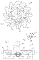
- the multiple disk 10 shown in FIG. 1 exists essentially, as shown in Figure 3, from a upper dispersing disc 11 and a lower dispersing disc 12 that are parallel to each other and coaxial to a dispersing shaft 14 are arranged.
- the dispersing disks 11 and 12 are through connecting webs 15 connected with each other.
- the dispersing disks 11 and 12 are at a uniform distance 30 from each other held and aligned.
- the connecting webs 15 are preferably rectangular, whereby the Side surfaces 39 are large.
- This geometric Form represents a sufficiently large and stable forehead and Support surface 37 for the dispersing disks 11, 12 and 12a ready. Oval shapes of the connecting webs 15 are also conceivable, since they also have flat surfaces exhibit.
- the upper dispersion disk 11 is arranged concentrically Provided suction openings 20, while the lower Dispersion disc 12 is closed.
- a multiple disc 10a is shown at which also includes the lower dispersing disc 12a with suction openings 21 is equipped.
- the dispersing disks 11, 12 and 12a have on their External circumferences teeth 16, 17 and 18, respectively, which are laminar Generate flow. Especially from the figures 3 and 5 it can be seen that the teeth 16, 17 and 18th with different setting angles 28 upwards and below from the plane of the dispersing disks 11, 12 and 12a are bounded.
- FIG. 3 shows an embodiment in which two different setting angles 28 are provided, whereby every second tooth 16 or 17 is equally set is.
- FIG. 5 shows an embodiment, in which every third tooth 16 or 17 or 18 is immediately restricted.
- the connecting webs 15 are by releasable connecting means 19 with the dispersing disks 11, 12 and 12a connected. As FIG. 2 shows in detail, these are Lanyard 19 screws in thread 29 in screwed the end faces 37 of the connecting webs 15 can be.
- the connecting webs 15 extend from the top of the dispersing disk 25 of the lower dispersing disc 12 to the underside of the dispersion disk 26 of the upper one Dispersing disc 11.
- the connecting webs 15 are concentric to the dispersing shaft 14 on the dispersing disks 11, 12 and 12a attached. Due to the lack of Mounting flanges, corresponds to the length of the connecting webs 15 essentially the distance 30 between the upper dispersing disk 11 and the lower dispersing disk 12 or 12a.
- the outer diameter 31 of the Dispersion disks 11, 12 and 12a are approximately five up to twenty times greater than the length 30 of the connecting webs 15 corresponds to.
- the connecting webs 15 a flattened side edge 24, the preferably facing the direction of rotation 38 (arrow) is. This will cause uncontrolled eddies in front of those caused by the rotating movement with dispersed material avoided sides.
- Other known aerodynamic Shapes of the connecting webs 15 are also conceivable insofar as they control the direction of flow influence.
- the connecting webs are 15 in a predetermined angle of attack 27 against one passing through the center 36 of the dispersing shaft 14 Radials 32 aligned.
- the angle of attack 27 the connecting webs are 15 smaller than 90 °, preferably 70 ° to 85 ° are provided.
- the releasable connecting means 19 make it possible to one of a multitude of connecting bridges of the same length 15 existing connecting web set against one exchange others, the longer or shorter ones Connecting webs 15 exist. This allows the distance 30 between the dispersing disks 11, 12 and 12a be set differently as required. It there is also the possibility of dispersing disks with different diameters and / or with different To combine teeth.
- the upper dispersing disc 11 has a central one Shaft bore 22 and the lower dispersing disk 12 or 12a has a central shaft bore 23, through which the dispersing shaft 14 is guided.
- the dispersion wave 14 is preferably a - not shown - Gear and by a - not shown Motor started to rotate. Especially in dispersion applications is a stepless regulation of the engine or the gearbox important for optimal dispersion results to reach.
- the shaft bore 22 of the upper dispersion disk 11 has a larger inner diameter 33 than that corresponds to the outer diameter 35 of the dispersing shaft 14.
- the dispersing shaft 14 is therefore contact-free passed through the upper dispersing disk 11.
- At the rotation of the multiple disc 10 or 10a arises such a suction through the shaft bore 22, which is a laminar Flow generated.
- the laminar flow extends through the shaft bore 22 here further to the radially outer Edge area of the multiple pane 10 or 10a.
- the inside diameter 33 not with the dispersing shaft 14 connected shaft bore 22 of the upper dispersion disk 11 is larger than the inner diameter 34 of the shaft bore 23 connected to the dispersing shaft 14 the lower dispersing disk 12 or 12a.
- the shaft bore 23 of the lower dispersing disk 12 or 12a corresponds approximately to the outer diameter 35 of the dispersing shaft 14.
- the dispersing disks 11, 12 and 12a have the same Outside diameter 31. In another version have the dispersing disks 11, 12 and 12a different Outside diameter 31.
- the dispersing disks have 11 and 12a suction openings 20 and 21, which are arranged concentrically spaced from the dispersing shaft 14 are.
- the lower dispersing disks are 12 and 12a in their central shaft bores 23 via fastening means 13 with the lower one free end of the dispersing shaft 14 connected.
- the inside diameter 34 of the shaft bores 23 correspond essentially the outer diameter 35 of the dispersing shaft 14.
Landscapes
- Chemical & Material Sciences (AREA)
- Chemical Kinetics & Catalysis (AREA)
- Dispersion Chemistry (AREA)
- Mixers Of The Rotary Stirring Type (AREA)
- Pigments, Carbon Blacks, Or Wood Stains (AREA)
- Physical Or Chemical Processes And Apparatus (AREA)
- Coloring (AREA)
- Mechanical Treatment Of Semiconductor (AREA)
Priority Applications (1)
| Application Number | Priority Date | Filing Date | Title |
|---|---|---|---|
| DE29825001U DE29825001U1 (de) | 1997-08-13 | 1998-08-12 | Dispergiervorrichtung zum allseitigen Benetzen von Primärteilchen pulveriger Stoffe |
Applications Claiming Priority (2)
| Application Number | Priority Date | Filing Date | Title |
|---|---|---|---|
| DE19735000A DE19735000C2 (de) | 1997-08-13 | 1997-08-13 | Dispergierwerkzeug zum allseitigen Benetzen von Primärteilchen pulveriger Stoffe |
| DE19735000 | 1997-08-13 |
Publications (3)
| Publication Number | Publication Date |
|---|---|
| EP0896834A2 true EP0896834A2 (fr) | 1999-02-17 |
| EP0896834A3 EP0896834A3 (fr) | 2001-01-31 |
| EP0896834B1 EP0896834B1 (fr) | 2003-11-12 |
Family
ID=7838804
Family Applications (1)
| Application Number | Title | Priority Date | Filing Date |
|---|---|---|---|
| EP98115120A Expired - Lifetime EP0896834B1 (fr) | 1997-08-13 | 1998-08-12 | Dispositif de dispersion pour le mouillage complet de materiau pulvérulent sous forme de particules primaires |
Country Status (3)
| Country | Link |
|---|---|
| EP (1) | EP0896834B1 (fr) |
| AT (1) | ATE253974T1 (fr) |
| DE (2) | DE19735000C2 (fr) |
Cited By (7)
| Publication number | Priority date | Publication date | Assignee | Title |
|---|---|---|---|---|
| EP1015102A4 (fr) * | 1997-08-20 | 2001-02-21 | Tva Technologies Pty Ltd | Dispositif melangeur et aerateur ameliore |
| US7473025B1 (en) * | 2008-01-31 | 2009-01-06 | Spx Corporation | Mixing impeller with spiral leading edge |
| EP2659958A1 (fr) * | 2012-05-03 | 2013-11-06 | WEPA Apothekenbedarf GmbH & Co.KG | Élément de mélange denté |
| CN103391809A (zh) * | 2011-03-14 | 2013-11-13 | 德国古斯塔夫·爱立许机械制造有限公司 | 用于颗粒化和结块的方法及用于该方法的工具 |
| JP2014236706A (ja) * | 2013-06-10 | 2014-12-18 | レオン自動機株式会社 | 食品への粉体付着装置および方法 |
| CN111905648A (zh) * | 2020-09-21 | 2020-11-10 | 重庆凯茜蔓科技有限公司 | 一种水包水艺术涂料精细造粒装置 |
| CN113427656A (zh) * | 2021-06-29 | 2021-09-24 | 安徽钢腾塑胶模具科技有限公司 | 一种熔融塑胶混料装置 |
Family Cites Families (13)
| Publication number | Priority date | Publication date | Assignee | Title |
|---|---|---|---|---|
| US2464588A (en) * | 1945-08-03 | 1949-03-15 | Pittsburgh Plate Glass Co | Machine for dispersing agglomerated pigments in liquids |
| US3030083A (en) * | 1959-03-25 | 1962-04-17 | Hugh A Stiffler | Agitator wheel |
| US2984462A (en) * | 1959-09-25 | 1961-05-16 | Donald J O'connor | Mixing device |
| US3071353A (en) * | 1961-03-13 | 1963-01-01 | Klein Sidney | Rotary mixing blade |
| US3486741A (en) * | 1968-02-06 | 1969-12-30 | Ernst L Midgette | Impeller |
| DE1941831B2 (de) * | 1969-08-16 | 1972-03-30 | Eirich, Wilhelm; Eirich, Gustav; 6969 Hardheim | Mischmaschine mit zwangsweise angetriebenem tellerfoermigem mischbehaelter |
| US3630636A (en) * | 1970-04-22 | 1971-12-28 | Continental Oil Co | Blade apparatus for high-shear mixing |
| US3999889A (en) * | 1975-10-23 | 1976-12-28 | Exxon Research And Engineering Company | Mixing head |
| DE8234623U1 (de) * | 1982-12-09 | 1983-05-05 | EKATO Industrieanlagen Verwaltungsgesellschaft mbH u. Co., 7860 Schopfheim | Ruehrvorrichtung |
| US4451155A (en) * | 1983-01-20 | 1984-05-29 | A. R. Wilfley And Sons, Inc. | Mixing device |
| DE3438766A1 (de) * | 1984-10-23 | 1986-04-24 | Lister GmbH Landgeräte- und Kühlanlagenfabrik, 5880 Lüdenscheid | Vorrichtung zur erzeugung einer wirbelbewegung in einer fluessigen oder pastoesen masse |
| DE3616203A1 (de) * | 1986-05-14 | 1987-11-19 | Plasty Spiel Und Sportartikel | Ruehrer fuer farben |
| US4813787A (en) * | 1987-07-23 | 1989-03-21 | Conn Leroy C | Blending apparatus |
-
1997
- 1997-08-13 DE DE19735000A patent/DE19735000C2/de not_active Expired - Fee Related
-
1998
- 1998-08-12 DE DE59810132T patent/DE59810132D1/de not_active Expired - Lifetime
- 1998-08-12 AT AT98115120T patent/ATE253974T1/de not_active IP Right Cessation
- 1998-08-12 EP EP98115120A patent/EP0896834B1/fr not_active Expired - Lifetime
Cited By (10)
| Publication number | Priority date | Publication date | Assignee | Title |
|---|---|---|---|---|
| EP1015102A4 (fr) * | 1997-08-20 | 2001-02-21 | Tva Technologies Pty Ltd | Dispositif melangeur et aerateur ameliore |
| US7473025B1 (en) * | 2008-01-31 | 2009-01-06 | Spx Corporation | Mixing impeller with spiral leading edge |
| AU2009210493B2 (en) * | 2008-01-31 | 2011-08-25 | Spx Flow, Inc. | Mixing impeller with spiral leading edge |
| CN103391809A (zh) * | 2011-03-14 | 2013-11-13 | 德国古斯塔夫·爱立许机械制造有限公司 | 用于颗粒化和结块的方法及用于该方法的工具 |
| CN103391809B (zh) * | 2011-03-14 | 2016-10-26 | 德国古斯塔夫·爱立许机械制造有限公司 | 用于颗粒化和结块的方法及用于该方法的工具 |
| US11014055B2 (en) | 2011-03-14 | 2021-05-25 | Maschinenfabrik Gustav Eirich Gmbh & Co Kg | Method for granulating or agglomerating and tool therefor |
| EP2659958A1 (fr) * | 2012-05-03 | 2013-11-06 | WEPA Apothekenbedarf GmbH & Co.KG | Élément de mélange denté |
| JP2014236706A (ja) * | 2013-06-10 | 2014-12-18 | レオン自動機株式会社 | 食品への粉体付着装置および方法 |
| CN111905648A (zh) * | 2020-09-21 | 2020-11-10 | 重庆凯茜蔓科技有限公司 | 一种水包水艺术涂料精细造粒装置 |
| CN113427656A (zh) * | 2021-06-29 | 2021-09-24 | 安徽钢腾塑胶模具科技有限公司 | 一种熔融塑胶混料装置 |
Also Published As
| Publication number | Publication date |
|---|---|
| DE19735000C2 (de) | 1999-10-21 |
| ATE253974T1 (de) | 2003-11-15 |
| EP0896834B1 (fr) | 2003-11-12 |
| DE19735000A1 (de) | 1999-02-25 |
| DE59810132D1 (de) | 2003-12-18 |
| EP0896834A3 (fr) | 2001-01-31 |
Similar Documents
| Publication | Publication Date | Title |
|---|---|---|
| DE102010008045B4 (de) | Rührflügel und abgedichtete Rührvorrichtung | |
| DE19947331C2 (de) | Dynamischer Mischer | |
| EP1471993B1 (fr) | Dispositif de dispersion | |
| DE69015577T2 (de) | Apparatus zur Behandlung viskoser Flüssigkeiten. | |
| DE602005000098T2 (de) | Dynamische Durchfluss-Mischvorrichtung | |
| WO2000021652A1 (fr) | Dispositif pour melanger deux matieres pateuses, en particulier pour melanger une matiere pour empreinte dentaire avec une matiere de catalyse | |
| EP0063171A2 (fr) | Dispositif mélangeur | |
| EP1925358B1 (fr) | Agitateur pour la fabrication d'une mélange liquide d'au moins de deux composantes, et utilisation d'un tel agitateur | |
| DE69700463T2 (de) | Rührdeckel für Farbbehälter, befestigt auf Farbrührmaschinen | |
| DE69630820T2 (de) | Mischer für viskose fluide | |
| EP0896834B1 (fr) | Dispositif de dispersion pour le mouillage complet de materiau pulvérulent sous forme de particules primaires | |
| DE1457270B2 (de) | Fluessigkeitsmischer | |
| DE202014002901U1 (de) | Klappmischer | |
| DE68914629T2 (de) | Vorrichtung zum Zerkleinern, Mischen und Dispergieren. | |
| DE10354888B4 (de) | Kolloidalmischer und Verfahren zur kolloidalen Aufbereitung einer Mischung | |
| DE4028108C1 (fr) | ||
| EP0305576B1 (fr) | Agitateur pour une machine à mélanger industrielle | |
| EP0125465A2 (fr) | Dispositif d'agitation | |
| DE29825001U1 (de) | Dispergiervorrichtung zum allseitigen Benetzen von Primärteilchen pulveriger Stoffe | |
| DE3820271A1 (de) | Homogenisierende mischvorrichtung | |
| DE112024001470T5 (de) | Knetvorrichtung | |
| EP1106243A2 (fr) | Mélangeur dynamique | |
| DE29724021U1 (de) | Dispergiervorrichtung zum allseitigen Benetzen von Primärteilchen pulveriger Stoffe | |
| DE10012072A1 (de) | Inline-Mischer | |
| DE19504033A1 (de) | Flügelscheibe für Rührwellen |
Legal Events
| Date | Code | Title | Description |
|---|---|---|---|
| PUAI | Public reference made under article 153(3) epc to a published international application that has entered the european phase |
Free format text: ORIGINAL CODE: 0009012 |
|
| AK | Designated contracting states |
Kind code of ref document: A2 Designated state(s): AT BE CH CY DE DK ES FI FR GB GR IE IT LI LU MC NL PT SE |
|
| AX | Request for extension of the european patent |
Free format text: AL;LT;LV;MK;RO;SI |
|
| PUAL | Search report despatched |
Free format text: ORIGINAL CODE: 0009013 |
|
| AK | Designated contracting states |
Kind code of ref document: A3 Designated state(s): AT BE CH CY DE DK ES FI FR GB GR IE IT LI LU MC NL PT SE |
|
| AX | Request for extension of the european patent |
Free format text: AL;LT;LV;MK;RO;SI |
|
| RIC1 | Information provided on ipc code assigned before grant |
Free format text: 7B 01F 7/26 A, 7B 01F 15/00 B |
|
| 17P | Request for examination filed |
Effective date: 20010208 |
|
| AKX | Designation fees paid |
Free format text: AT BE CH CY DE DK ES FI FR GB GR IE IT LI LU MC NL PT SE |
|
| 17Q | First examination report despatched |
Effective date: 20020624 |
|
| GRAH | Despatch of communication of intention to grant a patent |
Free format text: ORIGINAL CODE: EPIDOS IGRA |
|
| GRAS | Grant fee paid |
Free format text: ORIGINAL CODE: EPIDOSNIGR3 |
|
| GRAA | (expected) grant |
Free format text: ORIGINAL CODE: 0009210 |
|
| AK | Designated contracting states |
Kind code of ref document: B1 Designated state(s): AT BE CH CY DE DK ES FI FR GB GR IE IT LI LU MC NL PT SE |
|
| PG25 | Lapsed in a contracting state [announced via postgrant information from national office to epo] |
Ref country code: NL Free format text: LAPSE BECAUSE OF FAILURE TO SUBMIT A TRANSLATION OF THE DESCRIPTION OR TO PAY THE FEE WITHIN THE PRESCRIBED TIME-LIMIT Effective date: 20031112 Ref country code: IT Free format text: LAPSE BECAUSE OF FAILURE TO SUBMIT A TRANSLATION OF THE DESCRIPTION OR TO PAY THE FEE WITHIN THE PRESCRIBED TIME-LIMIT;WARNING: LAPSES OF ITALIAN PATENTS WITH EFFECTIVE DATE BEFORE 2007 MAY HAVE OCCURRED AT ANY TIME BEFORE 2007. THE CORRECT EFFECTIVE DATE MAY BE DIFFERENT FROM THE ONE RECORDED. Effective date: 20031112 Ref country code: IE Free format text: LAPSE BECAUSE OF FAILURE TO SUBMIT A TRANSLATION OF THE DESCRIPTION OR TO PAY THE FEE WITHIN THE PRESCRIBED TIME-LIMIT Effective date: 20031112 Ref country code: GB Free format text: LAPSE BECAUSE OF FAILURE TO SUBMIT A TRANSLATION OF THE DESCRIPTION OR TO PAY THE FEE WITHIN THE PRESCRIBED TIME-LIMIT Effective date: 20031112 Ref country code: FR Free format text: LAPSE BECAUSE OF FAILURE TO SUBMIT A TRANSLATION OF THE DESCRIPTION OR TO PAY THE FEE WITHIN THE PRESCRIBED TIME-LIMIT Effective date: 20031112 Ref country code: FI Free format text: LAPSE BECAUSE OF FAILURE TO SUBMIT A TRANSLATION OF THE DESCRIPTION OR TO PAY THE FEE WITHIN THE PRESCRIBED TIME-LIMIT Effective date: 20031112 Ref country code: CY Free format text: LAPSE BECAUSE OF FAILURE TO SUBMIT A TRANSLATION OF THE DESCRIPTION OR TO PAY THE FEE WITHIN THE PRESCRIBED TIME-LIMIT Effective date: 20031112 |
|
| REG | Reference to a national code |
Ref country code: GB Ref legal event code: FG4D Free format text: NOT ENGLISH |
|
| REG | Reference to a national code |
Ref country code: CH Ref legal event code: EP |
|
| REF | Corresponds to: |
Ref document number: 59810132 Country of ref document: DE Date of ref document: 20031218 Kind code of ref document: P |
|
| REG | Reference to a national code |
Ref country code: IE Ref legal event code: FG4D Free format text: GERMAN |
|
| PG25 | Lapsed in a contracting state [announced via postgrant information from national office to epo] |
Ref country code: SE Free format text: LAPSE BECAUSE OF FAILURE TO SUBMIT A TRANSLATION OF THE DESCRIPTION OR TO PAY THE FEE WITHIN THE PRESCRIBED TIME-LIMIT Effective date: 20040212 Ref country code: GR Free format text: LAPSE BECAUSE OF FAILURE TO SUBMIT A TRANSLATION OF THE DESCRIPTION OR TO PAY THE FEE WITHIN THE PRESCRIBED TIME-LIMIT Effective date: 20040212 Ref country code: DK Free format text: LAPSE BECAUSE OF FAILURE TO SUBMIT A TRANSLATION OF THE DESCRIPTION OR TO PAY THE FEE WITHIN THE PRESCRIBED TIME-LIMIT Effective date: 20040212 |
|
| PG25 | Lapsed in a contracting state [announced via postgrant information from national office to epo] |
Ref country code: ES Free format text: LAPSE BECAUSE OF FAILURE TO SUBMIT A TRANSLATION OF THE DESCRIPTION OR TO PAY THE FEE WITHIN THE PRESCRIBED TIME-LIMIT Effective date: 20040223 |
|
| NLV1 | Nl: lapsed or annulled due to failure to fulfill the requirements of art. 29p and 29m of the patents act | ||
| GBV | Gb: ep patent (uk) treated as always having been void in accordance with gb section 77(7)/1977 [no translation filed] |
Effective date: 20031112 |
|
| REG | Reference to a national code |
Ref country code: IE Ref legal event code: FD4D |
|
| PG25 | Lapsed in a contracting state [announced via postgrant information from national office to epo] |
Ref country code: LU Free format text: LAPSE BECAUSE OF NON-PAYMENT OF DUE FEES Effective date: 20040812 |
|
| PGFP | Annual fee paid to national office [announced via postgrant information from national office to epo] |
Ref country code: CH Payment date: 20040824 Year of fee payment: 7 Ref country code: AT Payment date: 20040824 Year of fee payment: 7 |
|
| PG25 | Lapsed in a contracting state [announced via postgrant information from national office to epo] |
Ref country code: MC Free format text: LAPSE BECAUSE OF NON-PAYMENT OF DUE FEES Effective date: 20040831 Ref country code: BE Free format text: LAPSE BECAUSE OF NON-PAYMENT OF DUE FEES Effective date: 20040831 |
|
| PLBE | No opposition filed within time limit |
Free format text: ORIGINAL CODE: 0009261 |
|
| STAA | Information on the status of an ep patent application or granted ep patent |
Free format text: STATUS: NO OPPOSITION FILED WITHIN TIME LIMIT |
|
| 26N | No opposition filed |
Effective date: 20040813 |
|
| EN | Fr: translation not filed | ||
| BERE | Be: lapsed |
Owner name: WILHELM *NIEMANN G.M.B.H. & CO. K.G. Effective date: 20040831 |
|
| PG25 | Lapsed in a contracting state [announced via postgrant information from national office to epo] |
Ref country code: AT Free format text: LAPSE BECAUSE OF NON-PAYMENT OF DUE FEES Effective date: 20050812 |
|
| PG25 | Lapsed in a contracting state [announced via postgrant information from national office to epo] |
Ref country code: LI Free format text: LAPSE BECAUSE OF NON-PAYMENT OF DUE FEES Effective date: 20050831 Ref country code: CH Free format text: LAPSE BECAUSE OF NON-PAYMENT OF DUE FEES Effective date: 20050831 |
|
| REG | Reference to a national code |
Ref country code: CH Ref legal event code: PL |
|
| BERE | Be: lapsed |
Owner name: WILHELM *NIEMANN G.M.B.H. & CO. K.G. Effective date: 20040831 |
|
| PG25 | Lapsed in a contracting state [announced via postgrant information from national office to epo] |
Ref country code: PT Free format text: LAPSE BECAUSE OF NON-PAYMENT OF DUE FEES Effective date: 20040412 |
|
| PGFP | Annual fee paid to national office [announced via postgrant information from national office to epo] |
Ref country code: DE Payment date: 20120830 Year of fee payment: 15 |
|
| PG25 | Lapsed in a contracting state [announced via postgrant information from national office to epo] |
Ref country code: DE Free format text: LAPSE BECAUSE OF NON-PAYMENT OF DUE FEES Effective date: 20140301 |
|
| REG | Reference to a national code |
Ref country code: DE Ref legal event code: R119 Ref document number: 59810132 Country of ref document: DE Effective date: 20140301 |