EP0896836A2 - Druckanlage zur Beschichtung eines Flächenmaterials mit einer Paste - Google Patents
Druckanlage zur Beschichtung eines Flächenmaterials mit einer Paste Download PDFInfo
- Publication number
- EP0896836A2 EP0896836A2 EP98108568A EP98108568A EP0896836A2 EP 0896836 A2 EP0896836 A2 EP 0896836A2 EP 98108568 A EP98108568 A EP 98108568A EP 98108568 A EP98108568 A EP 98108568A EP 0896836 A2 EP0896836 A2 EP 0896836A2
- Authority
- EP
- European Patent Office
- Prior art keywords
- paste
- coating
- printing
- counter roller
- sheet material
- Prior art date
- Legal status (The legal status is an assumption and is not a legal conclusion. Google has not performed a legal analysis and makes no representation as to the accuracy of the status listed.)
- Granted
Links
Images


Classifications
-
- B—PERFORMING OPERATIONS; TRANSPORTING
- B05—SPRAYING OR ATOMISING IN GENERAL; APPLYING FLUENT MATERIALS TO SURFACES, IN GENERAL
- B05C—APPARATUS FOR APPLYING FLUENT MATERIALS TO SURFACES, IN GENERAL
- B05C1/00—Apparatus in which liquid or other fluent material is applied to the surface of the work by contact with a member carrying the liquid or other fluent material, e.g. a porous member loaded with a liquid to be applied as a coating
- B05C1/04—Apparatus in which liquid or other fluent material is applied to the surface of the work by contact with a member carrying the liquid or other fluent material, e.g. a porous member loaded with a liquid to be applied as a coating for applying liquid or other fluent material to work of indefinite length
- B05C1/08—Apparatus in which liquid or other fluent material is applied to the surface of the work by contact with a member carrying the liquid or other fluent material, e.g. a porous member loaded with a liquid to be applied as a coating for applying liquid or other fluent material to work of indefinite length using a roller or other rotating member which contacts the work along a generating line
- B05C1/0826—Apparatus in which liquid or other fluent material is applied to the surface of the work by contact with a member carrying the liquid or other fluent material, e.g. a porous member loaded with a liquid to be applied as a coating for applying liquid or other fluent material to work of indefinite length using a roller or other rotating member which contacts the work along a generating line the work being a web or sheets
- B05C1/083—Apparatus in which liquid or other fluent material is applied to the surface of the work by contact with a member carrying the liquid or other fluent material, e.g. a porous member loaded with a liquid to be applied as a coating for applying liquid or other fluent material to work of indefinite length using a roller or other rotating member which contacts the work along a generating line the work being a web or sheets being passed between the coating roller and one or more backing rollers
-
- B—PERFORMING OPERATIONS; TRANSPORTING
- B05—SPRAYING OR ATOMISING IN GENERAL; APPLYING FLUENT MATERIALS TO SURFACES, IN GENERAL
- B05C—APPARATUS FOR APPLYING FLUENT MATERIALS TO SURFACES, IN GENERAL
- B05C1/00—Apparatus in which liquid or other fluent material is applied to the surface of the work by contact with a member carrying the liquid or other fluent material, e.g. a porous member loaded with a liquid to be applied as a coating
- B05C1/04—Apparatus in which liquid or other fluent material is applied to the surface of the work by contact with a member carrying the liquid or other fluent material, e.g. a porous member loaded with a liquid to be applied as a coating for applying liquid or other fluent material to work of indefinite length
- B05C1/08—Apparatus in which liquid or other fluent material is applied to the surface of the work by contact with a member carrying the liquid or other fluent material, e.g. a porous member loaded with a liquid to be applied as a coating for applying liquid or other fluent material to work of indefinite length using a roller or other rotating member which contacts the work along a generating line
- B05C1/0808—Details thereof, e.g. surface characteristics
-
- B—PERFORMING OPERATIONS; TRANSPORTING
- B05—SPRAYING OR ATOMISING IN GENERAL; APPLYING FLUENT MATERIALS TO SURFACES, IN GENERAL
- B05C—APPARATUS FOR APPLYING FLUENT MATERIALS TO SURFACES, IN GENERAL
- B05C1/00—Apparatus in which liquid or other fluent material is applied to the surface of the work by contact with a member carrying the liquid or other fluent material, e.g. a porous member loaded with a liquid to be applied as a coating
- B05C1/04—Apparatus in which liquid or other fluent material is applied to the surface of the work by contact with a member carrying the liquid or other fluent material, e.g. a porous member loaded with a liquid to be applied as a coating for applying liquid or other fluent material to work of indefinite length
- B05C1/08—Apparatus in which liquid or other fluent material is applied to the surface of the work by contact with a member carrying the liquid or other fluent material, e.g. a porous member loaded with a liquid to be applied as a coating for applying liquid or other fluent material to work of indefinite length using a roller or other rotating member which contacts the work along a generating line
- B05C1/10—Apparatus in which liquid or other fluent material is applied to the surface of the work by contact with a member carrying the liquid or other fluent material, e.g. a porous member loaded with a liquid to be applied as a coating for applying liquid or other fluent material to work of indefinite length using a roller or other rotating member which contacts the work along a generating line the liquid or other fluent material being supplied from inside the roller
-
- B—PERFORMING OPERATIONS; TRANSPORTING
- B05—SPRAYING OR ATOMISING IN GENERAL; APPLYING FLUENT MATERIALS TO SURFACES, IN GENERAL
- B05C—APPARATUS FOR APPLYING FLUENT MATERIALS TO SURFACES, IN GENERAL
- B05C11/00—Component parts, details or accessories not specifically provided for in groups B05C1/00 - B05C9/00
- B05C11/02—Apparatus for spreading or distributing liquids or other fluent materials already applied to a surface ; Controlling means therefor; Control of the thickness of a coating by spreading or distributing liquids or other fluent materials already applied to the coated surface
- B05C11/04—Apparatus for spreading or distributing liquids or other fluent materials already applied to a surface ; Controlling means therefor; Control of the thickness of a coating by spreading or distributing liquids or other fluent materials already applied to the coated surface with blades
- B05C11/041—Apparatus for spreading or distributing liquids or other fluent materials already applied to a surface ; Controlling means therefor; Control of the thickness of a coating by spreading or distributing liquids or other fluent materials already applied to the coated surface with blades characterised by means for positioning, loading, or deforming the blades
-
- B—PERFORMING OPERATIONS; TRANSPORTING
- B05—SPRAYING OR ATOMISING IN GENERAL; APPLYING FLUENT MATERIALS TO SURFACES, IN GENERAL
- B05C—APPARATUS FOR APPLYING FLUENT MATERIALS TO SURFACES, IN GENERAL
- B05C5/00—Apparatus in which liquid or other fluent material is projected, poured or allowed to flow on to the surface of the work
- B05C5/02—Apparatus in which liquid or other fluent material is projected, poured or allowed to flow on to the surface of the work the liquid or other fluent material being discharged through an outlet orifice by pressure, e.g. from an outlet device in contact or almost in contact, with the work
- B05C5/0245—Apparatus in which liquid or other fluent material is projected, poured or allowed to flow on to the surface of the work the liquid or other fluent material being discharged through an outlet orifice by pressure, e.g. from an outlet device in contact or almost in contact, with the work for applying liquid or other fluent material to a moving work of indefinite length, e.g. to a moving web
- B05C5/025—Apparatus in which liquid or other fluent material is projected, poured or allowed to flow on to the surface of the work the liquid or other fluent material being discharged through an outlet orifice by pressure, e.g. from an outlet device in contact or almost in contact, with the work for applying liquid or other fluent material to a moving work of indefinite length, e.g. to a moving web only at particular part of the work
Definitions
- the invention relates to a printing system for coating a surface material with a paste, in particular for Coating interlining nonwovens with an adhesive.
- Such printing systems are generally known and internal state of the art.
- the surface material is between a stencil and one with a elastic coating provided counter roll.
- the printing paste is applied to the surface material by Holes in a stencil with an internal squeegee. For Generation of a contact pressure of the squeegee against the printing stencil electromagnets are arranged in the counter roller.
- the mass application can be done via the contact pressure of the squeegee control of printing paste on the surface material, at least within certain limits.
- the bulk order in The squeegee can be moved in the transverse direction even when in use several, separately controlled electromagnets influence.
- the problem underlying the invention therefore exists in using a device to bulk in Control the transverse direction yourself during the printing process can to get a desired mass distribution.
- each zone can be controlled individually.
- Fig. 1 is a printing system for coating a Sheet material shown with a paste 1.
- the printing system has a printing stencil 2 with an internal squeegee 3 Apply a printing paste 4 through holes 5 in the Print template 2 on the surface material.
- the Sheet material 1 is between the printing template 2 and passed through a counter roller 6, an order of Paste 4 takes the form of points 7.
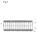
- Electromagnet 8 provided. These electromagnets 8 are located inside the counter roller 6 and pull the squeegee 3 over the entire width or over a partial area with a controllable magnetic attraction.
- the counter roller 6 is with a Cover 9 made of elastic material, for example silicone, provided, along which the sheet material 1 is guided is.
- the cover 9 made of elastic material enables Compensation for the different local changes in thickness of the Coating 10 on the surface of the counter roller 6.
- the apply a paste cold according to the invention where a desired, uniform mass distribution in Can be adjusted lengthways and crossways.
Landscapes
- Coating Apparatus (AREA)
Abstract
Description
- Fig. 1
- eine Druckanlage zum Auftrag einer Paste auf ein Vlies, die
- Fig. 2
- eine mit Piezoelementen versehene Gegenwalze in vergrößerter Darstellung und die
- Fig. 3
- die Piezoelemente mit elastischer Auflage ohne Walzenkörper im Längsschnitt.
Claims (1)
- Druckanlage zur Beschichtung eines Flächenmaterials (1) mit einer Paste (4), aufweisend eine Druckschablone (2) mit innenliegender Rakel (3) zum Auftrag der Druckpaste (4) durch Löcher (5) in der Druckschablone (2) auf das Flächenmaterial (1), eine Gegenwalze (6) und Mittel (8) zur Erzeugung eines Anpreßdrucks der Rakel (3) an die Druckschablone (2), dadurch gekennzeichnet, daß auf dem Walzenkörper (11) der Gegenwalze (6) eine auf die Breite bezogen in Abschnitte (12) eingeteilte Beschichtung (10) mit Piezoelementen vorgesehen ist, wobei jeder Abschnitt (12) einzeln ansteuerbar ist.
Applications Claiming Priority (2)
| Application Number | Priority Date | Filing Date | Title |
|---|---|---|---|
| DE19735026 | 1997-08-13 | ||
| DE19735026A DE19735026C1 (de) | 1997-08-13 | 1997-08-13 | Vorrichtung zur Beschichtung einer Materialbahn mit einer Paste |
Publications (3)
| Publication Number | Publication Date |
|---|---|
| EP0896836A2 true EP0896836A2 (de) | 1999-02-17 |
| EP0896836A3 EP0896836A3 (de) | 1999-06-16 |
| EP0896836B1 EP0896836B1 (de) | 2001-09-05 |
Family
ID=7838824
Family Applications (1)
| Application Number | Title | Priority Date | Filing Date |
|---|---|---|---|
| EP98108568A Expired - Lifetime EP0896836B1 (de) | 1997-08-13 | 1998-05-12 | Druckanlage zur Beschichtung eines Flächenmaterials mit einer Paste |
Country Status (3)
| Country | Link |
|---|---|
| US (1) | US5965220A (de) |
| EP (1) | EP0896836B1 (de) |
| DE (2) | DE19735026C1 (de) |
Families Citing this family (14)
| Publication number | Priority date | Publication date | Assignee | Title |
|---|---|---|---|---|
| JPH0975814A (ja) * | 1995-09-19 | 1997-03-25 | Fuji Photo Film Co Ltd | 塗布装置 |
| US5959466A (en) | 1997-01-31 | 1999-09-28 | Actel Corporation | Field programmable gate array with mask programmed input and output buffers |
| US6299571B1 (en) * | 1999-10-22 | 2001-10-09 | Morrison Berkshire, Inc. | System and method for controlling deflection of a dynamic surface |
| US6361483B1 (en) * | 1999-10-22 | 2002-03-26 | Morrison Berkshire, Inc. | System for controlling vibration of a dynamic surface |
| KR100370664B1 (ko) * | 1999-12-21 | 2003-02-05 | 선현호 | 소재표면의 돌출성형방법 및 그 장치 |
| DE10001364C2 (de) * | 2000-01-14 | 2002-08-14 | Windmoeller & Hoelscher | Auftragswalze zum Übertragen eines formatgerechten Klebstoffauftrags |
| US6564708B2 (en) * | 2000-05-26 | 2003-05-20 | Minami Co., Ltd. | Screen printing apparatus |
| US7461438B2 (en) * | 2004-03-03 | 2008-12-09 | Reifenhaeuser Gmbh & Co. Maschinenfabrik | Apparatus and method for applying finishing agents onto a nonwoven web |
| US8055166B2 (en) * | 2008-01-24 | 2011-11-08 | Xerox Corporation | Active image state control with linear distributed actuators on development rolls |
| US8050601B2 (en) * | 2008-01-24 | 2011-11-01 | Xerox Corporation | Smart donor rolls using individually addressable piezoelectric actuators |
| US8055165B2 (en) * | 2008-01-24 | 2011-11-08 | Xerox Corporation | Active image state control with distributed actuators and sensors on development rolls |
| US7869748B2 (en) * | 2008-01-24 | 2011-01-11 | Xerox Corporation | Direct imaging system with addressable actuators on a development roll |
| CN108525931B (zh) * | 2018-05-17 | 2020-11-13 | 惠州市瑞丰研磨材料有限公司 | 一种砂纸生产绒布砂纸上胶装置及其工作方法 |
| IT202000022621A1 (it) * | 2020-09-24 | 2022-03-24 | Ernesto Malvestiti S P A | Impianto e procedimento per la produzione di nuclei ferromagnetici di macchine elettriche |
Family Cites Families (12)
| Publication number | Priority date | Publication date | Assignee | Title |
|---|---|---|---|---|
| CH426711A (de) * | 1965-07-16 | 1966-12-31 | Aston Martin Co | Siebdruckmaschine mit Rundschablone |
| AT296927B (de) * | 1967-01-31 | 1972-03-10 | Peter Zimmer | Vorrichtung zum Auftragen von flüssigen oder pastösen Massen |
| DE1752374A1 (de) * | 1967-05-26 | 1971-05-19 | Zimmer Johannes | Rakeivorrichtung mit gleitendem Arbeitsorgan |
| DE1610300C3 (de) * | 1967-11-29 | 1975-08-07 | Erich 8133 Feldafing Weber | Rakelvorrichtung für Sieb- und Filmdruck |
| DE2851747C2 (de) * | 1978-11-30 | 1986-05-28 | Kleinewefers Gmbh, 4150 Krefeld | Druckbehandlungs- oder Transportwalze, insbesondere Kalanderwalze |
| GB2169820B (en) * | 1983-02-01 | 1987-08-19 | Molins Plc | Apparatus for applying adhesive |
| ES2041524T5 (es) * | 1989-01-09 | 1998-10-16 | Johannes Zimmer | Disposicion para la aplicacion de substancias sobre material en forma de banda. |
| AT400115B (de) * | 1990-01-17 | 1995-10-25 | Johannes Zimmer | Magnetisch angepresste rakel und rakelvorrichtung, insbesondere mit rundschablone (siebzylinder) |
| DE4209566A1 (de) * | 1991-03-21 | 1992-09-24 | Johannes Zimmer | Rakelgeraet |
| DE4201057C2 (de) * | 1992-01-17 | 1995-11-23 | Voith Gmbh J M | Auftrags- bzw. Dosiereinrichtung |
| DE4408615C2 (de) * | 1994-03-15 | 1996-01-11 | Roland Man Druckmasch | Näpfchenwalze innerhalb eines Auftragswerks einer Rotationsdruckmaschine |
| US5669303A (en) * | 1996-03-04 | 1997-09-23 | Motorola | Apparatus and method for stamping a surface |
-
1997
- 1997-08-13 DE DE19735026A patent/DE19735026C1/de not_active Expired - Fee Related
-
1998
- 1998-05-12 DE DE59801374T patent/DE59801374D1/de not_active Expired - Fee Related
- 1998-05-12 EP EP98108568A patent/EP0896836B1/de not_active Expired - Lifetime
- 1998-08-12 US US09/133,759 patent/US5965220A/en not_active Expired - Fee Related
Non-Patent Citations (1)
| Title |
|---|
| None |
Also Published As
| Publication number | Publication date |
|---|---|
| DE59801374D1 (de) | 2001-10-11 |
| US5965220A (en) | 1999-10-12 |
| EP0896836B1 (de) | 2001-09-05 |
| EP0896836A3 (de) | 1999-06-16 |
| DE19735026C1 (de) | 1999-05-27 |
Similar Documents
| Publication | Publication Date | Title |
|---|---|---|
| EP0896836B1 (de) | Druckanlage zur Beschichtung eines Flächenmaterials mit einer Paste | |
| DE19722159A1 (de) | Verfahren und Vorrichtung zum direkten oder indirekten Auftragen eines flüssigen oder pastösen Auftragsmediums auf eine laufende Oberfläche | |
| WO1989011938A1 (fr) | Procede et dispositif d'encollage et de brasage du support metallique d'un catalyseur | |
| DE2148655C3 (de) | Vorrichtung zum berührungsfreien Aufbringen einer Beschichtung auf einen Träger | |
| DE2361781A1 (de) | Schreibwerk zum schreiben mit fluessiger farbe | |
| DE2425679B2 (de) | Vorrichtung zum Erzeugen und selektiven Ablenken von Flüssigkeitströpfchen | |
| DE102009035152A1 (de) | Vorrichtung zum Aufbringen von mehreren Fäden eines Fluid | |
| EP1033245B1 (de) | Sprühfeuchtwerk mit hoher effektiver Sprühfrequenz | |
| DE4400769A1 (de) | Verfahren und Vorrichtung zur Herstellung einer flächigen Darreichungsform mit einer Arzneimittelwirkstoffe enthaltenden Zubereitung | |
| DE2312846B1 (de) | Führungs- und Transportvorrichtung für einen metallbeschichteten Aufzeichnungsträger | |
| DE1696153B2 (de) | Verfahren und Vorrichtung zum beidseitigen Aufbringen eines Strichs auf eine bewegte Papierbahn | |
| EP0896090A1 (de) | Verfahren zum direkten oder indirekten Auftragen eines flüssigen oder pastösen Mediums auf eine laufende Materialbahn, insbesondere aus Papier oder Karton | |
| EP0906788A2 (de) | Rakeleinrichtung für eine Vorrichtung zum Auftragen eines flüssigen bis pastösen Mediums auf einen sich vorbeibewegenden Untergrund | |
| DE2105575A1 (en) | Belt press - for plastic flow materials in continuous strip | |
| WO1997049499A1 (de) | Verfahren und vorrichtung zum dosierten aufbringen von flüssigkeiten auf materialbahnen | |
| CH679536A5 (de) | ||
| DE102009000639A1 (de) | Verfahren zum Beschichten eines Bandes, insbesondere einer Papiermaschinenbespannung | |
| EP0087716B1 (de) | Nadeldruckvorrichtung | |
| AT219266B (de) | Einrichtung zum schichtweisen Auftragen zweier Pulver unterschiedlicher Korngröße | |
| DE2145048C3 (de) | Vorrichtung zum Perforieren einer folienartigen Bahn mittels Funkenentladung | |
| DE19732552A1 (de) | Verfahren zum Herstellen von Verschlußelementen bei saugfähigen Hygieneartikeln zum einmaligen Gebrauch | |
| DE19610165A1 (de) | Vorrichtung zur Auto-Akupunktur und -Massage | |
| WO2000029126A1 (de) | Verfahren und vorrichtung zum auftragen von beschichtungsmaterial beim herstellen beschichteter und/oder imprägnierter flächengebilde | |
| AT361438B (de) | Rakelvorrichtung | |
| DE1147027B (de) | Vorrichtung zum schichtweisen Auftragen zweier fuer die Herstellung von gesinterten Kunststoffbahnen oder -platten geeigneter Kunststoffpulver unterschiedlicher Korngroesse auf eine bewegte Unterlage |
Legal Events
| Date | Code | Title | Description |
|---|---|---|---|
| PUAI | Public reference made under article 153(3) epc to a published international application that has entered the european phase |
Free format text: ORIGINAL CODE: 0009012 |
|
| AK | Designated contracting states |
Kind code of ref document: A2 Designated state(s): DE ES FR GB IT |
|
| AX | Request for extension of the european patent |
Free format text: AL;LT;LV;MK;RO;SI |
|
| PUAL | Search report despatched |
Free format text: ORIGINAL CODE: 0009013 |
|
| AK | Designated contracting states |
Kind code of ref document: A3 Designated state(s): AT BE CH CY DE DK ES FI FR GB GR IE IT LI LU MC NL PT SE |
|
| AX | Request for extension of the european patent |
Free format text: AL;LT;LV;MK;RO;SI |
|
| RIC1 | Information provided on ipc code assigned before grant |
Free format text: 6B 05C 11/04 A, 6B 05C 1/10 B, 6B 05C 1/08 B |
|
| 17P | Request for examination filed |
Effective date: 19990529 |
|
| AKX | Designation fees paid |
Free format text: DE ES FR GB IT |
|
| GRAG | Despatch of communication of intention to grant |
Free format text: ORIGINAL CODE: EPIDOS AGRA |
|
| GRAG | Despatch of communication of intention to grant |
Free format text: ORIGINAL CODE: EPIDOS AGRA |
|
| GRAH | Despatch of communication of intention to grant a patent |
Free format text: ORIGINAL CODE: EPIDOS IGRA |
|
| 17Q | First examination report despatched |
Effective date: 20010220 |
|
| GRAH | Despatch of communication of intention to grant a patent |
Free format text: ORIGINAL CODE: EPIDOS IGRA |
|
| GRAA | (expected) grant |
Free format text: ORIGINAL CODE: 0009210 |
|
| AK | Designated contracting states |
Kind code of ref document: B1 Designated state(s): DE ES FR GB IT |
|
| PG25 | Lapsed in a contracting state [announced via postgrant information from national office to epo] |
Ref country code: IT Free format text: LAPSE BECAUSE OF FAILURE TO SUBMIT A TRANSLATION OF THE DESCRIPTION OR TO PAY THE FEE WITHIN THE PRESCRIBED TIME-LIMIT;WARNING: LAPSES OF ITALIAN PATENTS WITH EFFECTIVE DATE BEFORE 2007 MAY HAVE OCCURRED AT ANY TIME BEFORE 2007. THE CORRECT EFFECTIVE DATE MAY BE DIFFERENT FROM THE ONE RECORDED. Effective date: 20010905 |
|
| REF | Corresponds to: |
Ref document number: 59801374 Country of ref document: DE Date of ref document: 20011011 |
|
| GBT | Gb: translation of ep patent filed (gb section 77(6)(a)/1977) |
Effective date: 20011026 |
|
| REG | Reference to a national code |
Ref country code: GB Ref legal event code: IF02 |
|
| ET | Fr: translation filed | ||
| RAP2 | Party data changed (patent owner data changed or rights of a patent transferred) |
Owner name: CARL FREUDENBERG KG |
|
| PG25 | Lapsed in a contracting state [announced via postgrant information from national office to epo] |
Ref country code: ES Free format text: LAPSE BECAUSE OF FAILURE TO SUBMIT A TRANSLATION OF THE DESCRIPTION OR TO PAY THE FEE WITHIN THE PRESCRIBED TIME-LIMIT Effective date: 20020326 |
|
| PLBE | No opposition filed within time limit |
Free format text: ORIGINAL CODE: 0009261 |
|
| STAA | Information on the status of an ep patent application or granted ep patent |
Free format text: STATUS: NO OPPOSITION FILED WITHIN TIME LIMIT |
|
| 26N | No opposition filed | ||
| PGFP | Annual fee paid to national office [announced via postgrant information from national office to epo] |
Ref country code: DE Payment date: 20030522 Year of fee payment: 6 |
|
| PGFP | Annual fee paid to national office [announced via postgrant information from national office to epo] |
Ref country code: GB Payment date: 20030618 Year of fee payment: 6 |
|
| PGFP | Annual fee paid to national office [announced via postgrant information from national office to epo] |
Ref country code: FR Payment date: 20030626 Year of fee payment: 6 |
|
| PG25 | Lapsed in a contracting state [announced via postgrant information from national office to epo] |
Ref country code: GB Free format text: LAPSE BECAUSE OF NON-PAYMENT OF DUE FEES Effective date: 20040512 |
|
| PG25 | Lapsed in a contracting state [announced via postgrant information from national office to epo] |
Ref country code: DE Free format text: LAPSE BECAUSE OF NON-PAYMENT OF DUE FEES Effective date: 20041201 |
|
| GBPC | Gb: european patent ceased through non-payment of renewal fee |
Effective date: 20040512 |
|
| PG25 | Lapsed in a contracting state [announced via postgrant information from national office to epo] |
Ref country code: FR Free format text: LAPSE BECAUSE OF NON-PAYMENT OF DUE FEES Effective date: 20050131 |
|
| REG | Reference to a national code |
Ref country code: FR Ref legal event code: ST |