EP0896891A2 - Dispositif de basculement pour toit ouvrant de véhicule et dispositif de montage de ce dispositif - Google Patents
Dispositif de basculement pour toit ouvrant de véhicule et dispositif de montage de ce dispositif Download PDFInfo
- Publication number
- EP0896891A2 EP0896891A2 EP98115054A EP98115054A EP0896891A2 EP 0896891 A2 EP0896891 A2 EP 0896891A2 EP 98115054 A EP98115054 A EP 98115054A EP 98115054 A EP98115054 A EP 98115054A EP 0896891 A2 EP0896891 A2 EP 0896891A2
- Authority
- EP
- European Patent Office
- Prior art keywords
- spring
- axis
- rocker
- opening
- respect
- Prior art date
- Legal status (The legal status is an assumption and is not a legal conclusion. Google has not performed a legal analysis and makes no representation as to the accuracy of the status listed.)
- Withdrawn
Links
- 238000000034 method Methods 0.000 title claims abstract description 6
- 230000002093 peripheral effect Effects 0.000 claims description 2
- 230000036316 preload Effects 0.000 description 3
- 241000446313 Lamella Species 0.000 description 2
- 239000002131 composite material Substances 0.000 description 1
- 230000002427 irreversible effect Effects 0.000 description 1
- 238000004519 manufacturing process Methods 0.000 description 1
- 239000000463 material Substances 0.000 description 1
Images
Classifications
-
- B—PERFORMING OPERATIONS; TRANSPORTING
- B60—VEHICLES IN GENERAL
- B60J—WINDOWS, WINDSCREENS, NON-FIXED ROOFS, DOORS, OR SIMILAR DEVICES FOR VEHICLES; REMOVABLE EXTERNAL PROTECTIVE COVERINGS SPECIALLY ADAPTED FOR VEHICLES
- B60J7/00—Non-fixed roofs; Roofs with movable panels, e.g. rotary sunroofs
- B60J7/02—Non-fixed roofs; Roofs with movable panels, e.g. rotary sunroofs of sliding type, e.g. comprising guide shoes
- B60J7/04—Non-fixed roofs; Roofs with movable panels, e.g. rotary sunroofs of sliding type, e.g. comprising guide shoes with rigid plate-like element or elements, e.g. open roofs with harmonica-type folding rigid panels
- B60J7/047—Non-fixed roofs; Roofs with movable panels, e.g. rotary sunroofs of sliding type, e.g. comprising guide shoes with rigid plate-like element or elements, e.g. open roofs with harmonica-type folding rigid panels movable to overlapping or nested relationship
-
- Y—GENERAL TAGGING OF NEW TECHNOLOGICAL DEVELOPMENTS; GENERAL TAGGING OF CROSS-SECTIONAL TECHNOLOGIES SPANNING OVER SEVERAL SECTIONS OF THE IPC; TECHNICAL SUBJECTS COVERED BY FORMER USPC CROSS-REFERENCE ART COLLECTIONS [XRACs] AND DIGESTS
- Y10—TECHNICAL SUBJECTS COVERED BY FORMER USPC
- Y10T—TECHNICAL SUBJECTS COVERED BY FORMER US CLASSIFICATION
- Y10T403/00—Joints and connections
- Y10T403/32—Articulated members
- Y10T403/32606—Pivoted
- Y10T403/32819—Pivoted including tension or take-up means
- Y10T403/32827—Interposed spring means coaxial with pivot
Definitions
- the invention relates to a rocker device for an openable vehicle roof, with a Carrier element, a rocker element and a spring, the rocker element over an axis is pivotally connected to the carrier element and the spring between rocker element and Carrier element is arranged so that the rocking element with a biasing force a direction of the pivoting movement.
- the invention is also a Method of assembling such a device
- Such a generic device is known from DE 196 08 916 C1.
- the forms Rocker device each a part of swing-out fasteners for Slat roof.
- Fastening element which forms the support element of the rocker device, is as Latching rocker formed by means of the axis designed as a pivot bearing pivotally attached to the adjusting element.
- the swivel bearing consists of a riveted eyelet.
- the spring designed as a spiral spring is attached to the pivot bearing, around the locking rocker with the swivel preload with respect to the adjusting element act upon.
- the disadvantage here is that the axial securing of the rocker element by means of a riveted eyelet is relatively complex, the disassembly difficult and also an axial play between Rocker element and support element allowed.
- This task is based on a rocker device with the aforementioned Features solved in that the spring is arranged and designed so that it is also for a biasing force in an axial direction between the rocker member and the support member provides, and that the axis is fixed with respect to one element and by a corresponding axis opening is guided in the other element.
- This solution according to the invention is advantageous in that the rocking device with minimal Number of parts can be set up very easily and is quick and easy to assemble easy disassembly is possible, the spring allows axial tolerance compensation and further there is axial freedom from play, which ensures freedom from rattling during operation.
- the spring as a spiral spring is formed, which is arranged concentrically to the axis, the one spring end is fixed with respect to the axis and the other spring end with respect to the other element is certain.
- the spring is arranged at the free end of the axis and runs around the axis, the inner spring end in a receiving opening in the Axis is inserted and the outer spring end as U-shaped in the spring plane to the outside curved leg is formed, which has a projection on the corresponding element embraces.
- the axis at its free end with an axially in the Circumferential surface trained mounting groove that to the free end of the axis towards the center of the axis is chamfered, is provided, at the other end of the receiving opening as radial extending cylindrical opening is formed, and also that the inner spring end in is essentially formed as a straight piece running radially in the spring plane.
- the axis is preferably formed in one piece with the rocker element. This poses a particularly simple structure.
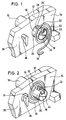
- an axis 10 which is integrally connected to a rocker element 12 which, for example, a latch rocker for a fastening element of a lamella roof, as described in DE 196 08 916 C1, is pushed through an axis opening 16 formed in a carrier element 14.
- carrier element 14 forms an adjusting element, as is described in DE 196 08 916 C1 is described.
- the carrier element 14 and the rocker element 12 are shown in FIG. 1 and 2 only shown schematically or in sections.
- the axis 10 is formed at its free end 18 with an axially in the peripheral surface 20
- Mounting groove 22 provided to the free end 18 of the axis 10 towards the center of the axis beveled, i.e. is provided with an inclined surface 24.
- the other End 26 of the mounting groove 22 is a receiving opening 28 as a radial cylindrical one Opening trained.
- a coil spring 30 is provided with its inner end 32, which is essentially radial in the A straight piece running in the spring plane is formed, so at the free end 18 of the axis 10 assumed that the inner end 32 of the spring 30 engages in the mounting groove 22 and thereby on the inclined surface 24 is present.
- the spring 30 is then in the axial direction via the axis 10 pushed until the inner spring end 32 engages in the receiving opening 28.
- the length of the inner spring end 32 is selected so that the spring tension, the inner spring end 32 in the Presses the receiving opening 28 in and holds it.
- the spring 30 is now seated on the axis 10 or runs around them.
- the outer spring end 34 is a leg which is bent outward in a U-shape in the spring plane formed, which initially lies approximately opposite the inner spring end 32. The following will the leg 34 is rotated clockwise against the tangential bias of the spring 30, until it engages around a projection 36 formed on the carrier element 14. In this position the leg 34 is held by the tangential spring force, see FIG. 2nd
- the receiving opening 28 with the inner spring end 32 is arranged so that at Absence of external forces due to the axial spring force a certain distance from the edge of the axis opening 16 or the side surface 38 of the carrier element 14 is removed.
- the spring 30 acts on the rocker element 12 with an axial preload with respect to the carrier element 14, so that on the one hand manufacturing tolerances are compensated for and on the other hand an axial play between the rocker element 12 and the support element 14 is prevented, which lead to undesirable rattling noises during operation can.
- the spring 30 provides for the Bolt rocker function required pivoting bias of the rocker element 12 (or the Bolt rocker) with respect to the carrier element 14.
- the rocker can also be easily dismantled.
Landscapes
- Engineering & Computer Science (AREA)
- Mechanical Engineering (AREA)
- Lock And Its Accessories (AREA)
- Fittings On The Vehicle Exterior For Carrying Loads, And Devices For Holding Or Mounting Articles (AREA)
- Automobile Manufacture Line, Endless Track Vehicle, Trailer (AREA)
Applications Claiming Priority (2)
| Application Number | Priority Date | Filing Date | Title |
|---|---|---|---|
| DE19735182A DE19735182C1 (de) | 1997-08-14 | 1997-08-14 | Wippvorrichtung für ein öffnungsfähiges Fahrzeugdach und Verfahren zur Montage einer solchen Vorrichtung |
| DE19735182 | 1997-08-14 |
Publications (2)
| Publication Number | Publication Date |
|---|---|
| EP0896891A2 true EP0896891A2 (fr) | 1999-02-17 |
| EP0896891A3 EP0896891A3 (fr) | 2000-09-13 |
Family
ID=7838912
Family Applications (1)
| Application Number | Title | Priority Date | Filing Date |
|---|---|---|---|
| EP98115054A Withdrawn EP0896891A3 (fr) | 1997-08-14 | 1998-08-11 | Dispositif de basculement pour toit ouvrant de véhicule et dispositif de montage de ce dispositif |
Country Status (4)
| Country | Link |
|---|---|
| US (1) | US6261024B1 (fr) |
| EP (1) | EP0896891A3 (fr) |
| JP (1) | JPH1170856A (fr) |
| DE (1) | DE19735182C1 (fr) |
Families Citing this family (5)
| Publication number | Priority date | Publication date | Assignee | Title |
|---|---|---|---|---|
| NL1010671C2 (nl) * | 1998-11-27 | 2000-06-07 | Inalfa Ind Bv | Open-dakconstructie voor een voertuig. |
| TW468734U (en) * | 2001-04-13 | 2001-12-11 | Great Lotus Corp | Automatically position recovering universal joint |
| DE10331568A1 (de) | 2003-07-11 | 2005-01-27 | Robert Bosch Gmbh | Scheibenwischvorrichtung, insbesondere für ein Kraftfahrzeug |
| JP5393850B1 (ja) | 2012-07-23 | 2014-01-22 | 株式会社小松製作所 | ワイパ装置、ワイパ装置付開閉ガード、および建設機械のためのキャブ |
| DE102012106975B4 (de) * | 2012-07-31 | 2023-04-13 | Dr. Ing. H.C. F. Porsche Aktiengesellschaft | Vorrichtung und Verfahren zum Ausrichten eines Verdecklagers |
Citations (1)
| Publication number | Priority date | Publication date | Assignee | Title |
|---|---|---|---|---|
| DE19608916C1 (de) | 1996-03-07 | 1997-04-17 | Webasto Karosseriesysteme | Fahrzeugdach mit einer Folge von ausstellbaren Deckelelementen |
Family Cites Families (20)
| Publication number | Priority date | Publication date | Assignee | Title |
|---|---|---|---|---|
| DE634087C (de) * | 1935-12-22 | 1936-08-15 | Anton Ullmann | Federanordnung fuer Sturmstangen |
| GB811585A (en) * | 1956-07-20 | 1959-04-08 | Francis Walter Norman Duffield | Improvements in, or relating to, clevis joints |
| US3861635A (en) * | 1973-05-21 | 1975-01-21 | Albert L Juris | Extendable adjustable mailbox support means |
| US4102439A (en) * | 1976-05-28 | 1978-07-25 | Richard N. Jayson | Torque reaction operated bicycle braking system and mounting structure |
| US4138838A (en) * | 1977-08-01 | 1979-02-13 | Sperry Rand Corporation | Locking mechanism for rake basket crank |
| US4192622A (en) * | 1979-03-15 | 1980-03-11 | Deere & Company | Articulated joint including Belleville spring seals maintained in a preselected compressed state |
| US4447170A (en) * | 1982-03-02 | 1984-05-08 | Ralph Holmes | Connection assembly for use with an articulated linkage system |
| US4589497A (en) * | 1984-05-14 | 1986-05-20 | Kovar Jack J | Spring tooth harrow, and spring tooth and tooth clip for a harrow |
| US4709445A (en) * | 1985-08-13 | 1987-12-01 | Ideal Security Hardward Corporation | Method and apparatus for closing a door |
| US4932807A (en) * | 1988-07-28 | 1990-06-12 | The United States Of America As Represented By The Administrator Of The National Aeronautics And Space Administration | Clevis joint for deployable space structures |
| JPH03119611U (fr) * | 1990-01-30 | 1991-12-10 | ||
| US5022778A (en) * | 1990-11-02 | 1991-06-11 | Lu Sheng N | Pivot shaft |
| DE4124204A1 (de) * | 1991-07-20 | 1993-01-21 | Deere & Co | Verbindung zwischen abgasrohr und endrohr |
| JP3266700B2 (ja) * | 1993-07-02 | 2002-03-18 | 本田技研工業株式会社 | 押出し部材と相手部材との接合構造および接合方法 |
| US5467504A (en) * | 1994-02-04 | 1995-11-21 | Chiahuan Spring Co., Ltd. | Hinge for a portable computer |
| US5566048A (en) * | 1994-06-02 | 1996-10-15 | Hewlett-Packard Company | Hinge assembly for a device having a display |
| US5555954A (en) * | 1994-07-29 | 1996-09-17 | Emerson Electric Co. | Collapsible-expansible support assembly |
| US5593265A (en) * | 1995-08-16 | 1997-01-14 | Chrysler Corporation | Quick-connect stored energy torsional fastener |
| US5820279A (en) * | 1995-09-22 | 1998-10-13 | Eltron International, Inc. | Computer driven printer |
| DE19649741C2 (de) * | 1996-11-30 | 1999-07-15 | Daimler Benz Aerospace Ag | Gelenk zum Entfalten und Verriegeln einer Solarpaneele oder eines Reflektors |
-
1997
- 1997-08-14 DE DE19735182A patent/DE19735182C1/de not_active Expired - Fee Related
-
1998
- 1998-06-24 JP JP10177381A patent/JPH1170856A/ja active Pending
- 1998-08-11 EP EP98115054A patent/EP0896891A3/fr not_active Withdrawn
- 1998-08-13 US US09/133,329 patent/US6261024B1/en not_active Expired - Fee Related
Patent Citations (1)
| Publication number | Priority date | Publication date | Assignee | Title |
|---|---|---|---|---|
| DE19608916C1 (de) | 1996-03-07 | 1997-04-17 | Webasto Karosseriesysteme | Fahrzeugdach mit einer Folge von ausstellbaren Deckelelementen |
Also Published As
| Publication number | Publication date |
|---|---|
| JPH1170856A (ja) | 1999-03-16 |
| EP0896891A3 (fr) | 2000-09-13 |
| US6261024B1 (en) | 2001-07-17 |
| DE19735182C1 (de) | 1998-09-24 |
Similar Documents
| Publication | Publication Date | Title |
|---|---|---|
| EP2318723B1 (fr) | Agencement de fixation avec compensation des tolerances | |
| EP1979634B1 (fr) | Unité de montage destinée à un anneau de fixation d'une boucle de ceinture | |
| EP0231440B1 (fr) | Pare-soleil pour véhicules | |
| DE69501940T2 (de) | Abnehmbare Befestigung eines Fahrzeugsitzuntergestells auf einem Boden | |
| EP0513562A1 (fr) | Dispositif de transport | |
| DE19741605B4 (de) | Befestigungsvorrichtung für einen Scheinwerfer an einem Kraftfahrzeug | |
| EP2019765A1 (fr) | Dispositif et procédé pour fixer un moteur d'essuie-glace sur une tringlerie d'essuie-glace | |
| DE3218325A1 (de) | Kupplungsausruecklager, insbesondere fuer kraftfahrzeuge | |
| DE102021133093A1 (de) | Türgriffanordnung für ein fahrzeug sowie verfahren zur montage einer türgriffanordnung | |
| DE3884571T2 (de) | Lenksäulenverbindung. | |
| DE19643234C1 (de) | Windabweiser für Fahrzeug-Dachöffnung | |
| DE19735182C1 (de) | Wippvorrichtung für ein öffnungsfähiges Fahrzeugdach und Verfahren zur Montage einer solchen Vorrichtung | |
| DE69601959T2 (de) | Montagevorrichtung für Rad und mit Laufrädern versehener, mit solcher Vorrichtung ausgerüsteter, Müllsammelbehälter | |
| EP1565348B1 (fr) | Systeme d'actionnement d'avertisseur sonore monte au volant | |
| DE4204630C2 (de) | Kugelraste für die Lagefixierung eines beweglichen Stellelementes | |
| DE19923487A1 (de) | Widerlager mit Formteil zum Befestigen von Betätigungszügen | |
| DE19921810B4 (de) | Rastbeschlag für einen Fahrzeugsitz | |
| DE60313504T2 (de) | Seitliche halteeinrichtung für personenförderband | |
| EP0788951A1 (fr) | Bras d'essuie-glace d'un dispositif de balayage de pare-brise de véhicule | |
| DE102020104949B4 (de) | Schienenanordnung für einen Fahrzeugsitz, Fahrzeugsitz und Verfahren zum Montieren der Schienenanordnung | |
| WO2012041541A1 (fr) | Fourchette de boîte de vitesses possédant des patins coulissants | |
| DE4326547C1 (de) | Befestigungsvorrichtung für einen Himmel | |
| DE102021004499A1 (de) | Kupplungsvorrichtung mit Sperrklinkeneinrichtung und Sperrklinkeneinrichtung für eine solche Kupplungsvorrichtung | |
| DE19904713C1 (de) | Vorrichtung zur axialen Festlegung eines Bolzens | |
| DE4403440C2 (de) | Verschlußgehäuse |
Legal Events
| Date | Code | Title | Description |
|---|---|---|---|
| PUAI | Public reference made under article 153(3) epc to a published international application that has entered the european phase |
Free format text: ORIGINAL CODE: 0009012 |
|
| AK | Designated contracting states |
Kind code of ref document: A2 Designated state(s): DE ES FR GB IT NL |
|
| AX | Request for extension of the european patent |
Free format text: AL;LT;LV;MK;RO;SI |
|
| PUAL | Search report despatched |
Free format text: ORIGINAL CODE: 0009013 |
|
| AK | Designated contracting states |
Kind code of ref document: A3 Designated state(s): AT BE CH CY DE DK ES FI FR GB GR IE IT LI LU MC NL PT SE |
|
| AX | Request for extension of the european patent |
Free format text: AL;LT;LV;MK;RO;SI |
|
| 17P | Request for examination filed |
Effective date: 20001110 |
|
| AKX | Designation fees paid |
Free format text: DE ES FR GB IT NL |
|
| 17Q | First examination report despatched |
Effective date: 20020411 |
|
| GRAP | Despatch of communication of intention to grant a patent |
Free format text: ORIGINAL CODE: EPIDOSNIGR1 |
|
| STAA | Information on the status of an ep patent application or granted ep patent |
Free format text: STATUS: THE APPLICATION IS DEEMED TO BE WITHDRAWN |
|
| 18D | Application deemed to be withdrawn |
Effective date: 20031028 |