EP0897196B1 - Verfahren zum Herstellen einer isolierenden Komponente für eine Hochtemperatur-Brennstoffzelle und Hochtemperatur-Brennstoffzelle - Google Patents
Verfahren zum Herstellen einer isolierenden Komponente für eine Hochtemperatur-Brennstoffzelle und Hochtemperatur-Brennstoffzelle Download PDFInfo
- Publication number
- EP0897196B1 EP0897196B1 EP97114006A EP97114006A EP0897196B1 EP 0897196 B1 EP0897196 B1 EP 0897196B1 EP 97114006 A EP97114006 A EP 97114006A EP 97114006 A EP97114006 A EP 97114006A EP 0897196 B1 EP0897196 B1 EP 0897196B1
- Authority
- EP
- European Patent Office
- Prior art keywords
- layer
- insulating component
- temperature fuel
- temperature
- process according
- Prior art date
- Legal status (The legal status is an assumption and is not a legal conclusion. Google has not performed a legal analysis and makes no representation as to the accuracy of the status listed.)
- Expired - Lifetime
Links
- 238000004519 manufacturing process Methods 0.000 title abstract description 13
- 239000000446 fuel Substances 0.000 claims abstract description 32
- 238000000034 method Methods 0.000 claims abstract description 31
- 239000006185 dispersion Substances 0.000 claims abstract description 13
- XLYOFNOQVPJJNP-UHFFFAOYSA-N water Substances O XLYOFNOQVPJJNP-UHFFFAOYSA-N 0.000 claims abstract description 13
- 229910010293 ceramic material Inorganic materials 0.000 claims abstract description 12
- 238000005245 sintering Methods 0.000 claims abstract description 12
- 239000011230 binding agent Substances 0.000 claims abstract description 8
- 239000003232 water-soluble binding agent Substances 0.000 claims abstract description 4
- 238000006243 chemical reaction Methods 0.000 claims description 2
- 238000002360 preparation method Methods 0.000 claims description 2
- 238000000280 densification Methods 0.000 claims 2
- 238000007596 consolidation process Methods 0.000 claims 1
- 239000000919 ceramic Substances 0.000 abstract description 3
- 238000003754 machining Methods 0.000 abstract description 2
- 238000005266 casting Methods 0.000 abstract 1
- 239000010410 layer Substances 0.000 description 32
- 239000002131 composite material Substances 0.000 description 17
- 239000003792 electrolyte Substances 0.000 description 7
- 238000007789 sealing Methods 0.000 description 7
- 238000003860 storage Methods 0.000 description 7
- 239000011651 chromium Substances 0.000 description 5
- CURLTUGMZLYLDI-UHFFFAOYSA-N Carbon dioxide Chemical compound O=C=O CURLTUGMZLYLDI-UHFFFAOYSA-N 0.000 description 4
- VYZAMTAEIAYCRO-UHFFFAOYSA-N Chromium Chemical compound [Cr] VYZAMTAEIAYCRO-UHFFFAOYSA-N 0.000 description 4
- 229910045601 alloy Inorganic materials 0.000 description 4
- 239000000956 alloy Substances 0.000 description 4
- 229910052804 chromium Inorganic materials 0.000 description 4
- 239000000463 material Substances 0.000 description 4
- 239000000203 mixture Substances 0.000 description 4
- 229910052596 spinel Inorganic materials 0.000 description 4
- 239000011029 spinel Substances 0.000 description 4
- QVGXLLKOCUKJST-UHFFFAOYSA-N atomic oxygen Chemical compound [O] QVGXLLKOCUKJST-UHFFFAOYSA-N 0.000 description 3
- 239000001257 hydrogen Substances 0.000 description 3
- 229910052739 hydrogen Inorganic materials 0.000 description 3
- 125000004435 hydrogen atom Chemical class [H]* 0.000 description 3
- 239000000395 magnesium oxide Substances 0.000 description 3
- CPLXHLVBOLITMK-UHFFFAOYSA-N magnesium oxide Inorganic materials [Mg]=O CPLXHLVBOLITMK-UHFFFAOYSA-N 0.000 description 3
- AXZKOIWUVFPNLO-UHFFFAOYSA-N magnesium;oxygen(2-) Chemical compound [O-2].[Mg+2] AXZKOIWUVFPNLO-UHFFFAOYSA-N 0.000 description 3
- 239000001301 oxygen Substances 0.000 description 3
- 229910052760 oxygen Inorganic materials 0.000 description 3
- 238000007711 solidification Methods 0.000 description 3
- 230000008023 solidification Effects 0.000 description 3
- 229910018072 Al 2 O 3 Inorganic materials 0.000 description 2
- 239000001569 carbon dioxide Substances 0.000 description 2
- 229910002092 carbon dioxide Inorganic materials 0.000 description 2
- 239000003344 environmental pollutant Substances 0.000 description 2
- 239000002737 fuel gas Substances 0.000 description 2
- VNWKTOKETHGBQD-UHFFFAOYSA-N methane Chemical compound C VNWKTOKETHGBQD-UHFFFAOYSA-N 0.000 description 2
- 231100000719 pollutant Toxicity 0.000 description 2
- 238000007493 shaping process Methods 0.000 description 2
- MYMOFIZGZYHOMD-UHFFFAOYSA-N Dioxygen Chemical compound O=O MYMOFIZGZYHOMD-UHFFFAOYSA-N 0.000 description 1
- 238000001354 calcination Methods 0.000 description 1
- 239000003034 coal gas Substances 0.000 description 1
- 239000013078 crystal Substances 0.000 description 1
- 238000011161 development Methods 0.000 description 1
- 230000018109 developmental process Effects 0.000 description 1
- UAMZXLIURMNTHD-UHFFFAOYSA-N dialuminum;magnesium;oxygen(2-) Chemical group [O-2].[O-2].[O-2].[O-2].[Mg+2].[Al+3].[Al+3] UAMZXLIURMNTHD-UHFFFAOYSA-N 0.000 description 1
- 238000005553 drilling Methods 0.000 description 1
- 238000010292 electrical insulation Methods 0.000 description 1
- 238000005868 electrolysis reaction Methods 0.000 description 1
- 239000002803 fossil fuel Substances 0.000 description 1
- 239000007789 gas Substances 0.000 description 1
- 238000000227 grinding Methods 0.000 description 1
- 229910052749 magnesium Inorganic materials 0.000 description 1
- 239000011777 magnesium Substances 0.000 description 1
- -1 magnesium aluminate Chemical class 0.000 description 1
- 239000012528 membrane Substances 0.000 description 1
- 238000003801 milling Methods 0.000 description 1
- 239000003345 natural gas Substances 0.000 description 1
- TWNQGVIAIRXVLR-UHFFFAOYSA-N oxo(oxoalumanyloxy)alumane Chemical compound O=[Al]O[Al]=O TWNQGVIAIRXVLR-UHFFFAOYSA-N 0.000 description 1
- 239000011241 protective layer Substances 0.000 description 1
- 239000011265 semifinished product Substances 0.000 description 1
- 229910000679 solder Inorganic materials 0.000 description 1
- 239000007784 solid electrolyte Substances 0.000 description 1
Images

Classifications
-
- C—CHEMISTRY; METALLURGY
- C04—CEMENTS; CONCRETE; ARTIFICIAL STONE; CERAMICS; REFRACTORIES
- C04B—LIME, MAGNESIA; SLAG; CEMENTS; COMPOSITIONS THEREOF, e.g. MORTARS, CONCRETE OR LIKE BUILDING MATERIALS; ARTIFICIAL STONE; CERAMICS; REFRACTORIES; TREATMENT OF NATURAL STONE
- C04B35/00—Shaped ceramic products characterised by their composition; Ceramics compositions; Processing powders of inorganic compounds preparatory to the manufacturing of ceramic products
- C04B35/622—Forming processes; Processing powders of inorganic compounds preparatory to the manufacturing of ceramic products
-
- C—CHEMISTRY; METALLURGY
- C04—CEMENTS; CONCRETE; ARTIFICIAL STONE; CERAMICS; REFRACTORIES
- C04B—LIME, MAGNESIA; SLAG; CEMENTS; COMPOSITIONS THEREOF, e.g. MORTARS, CONCRETE OR LIKE BUILDING MATERIALS; ARTIFICIAL STONE; CERAMICS; REFRACTORIES; TREATMENT OF NATURAL STONE
- C04B35/00—Shaped ceramic products characterised by their composition; Ceramics compositions; Processing powders of inorganic compounds preparatory to the manufacturing of ceramic products
- C04B35/01—Shaped ceramic products characterised by their composition; Ceramics compositions; Processing powders of inorganic compounds preparatory to the manufacturing of ceramic products based on oxide ceramics
- C04B35/44—Shaped ceramic products characterised by their composition; Ceramics compositions; Processing powders of inorganic compounds preparatory to the manufacturing of ceramic products based on oxide ceramics based on aluminates
- C04B35/443—Magnesium aluminate spinel
-
- H—ELECTRICITY
- H01—ELECTRIC ELEMENTS
- H01M—PROCESSES OR MEANS, e.g. BATTERIES, FOR THE DIRECT CONVERSION OF CHEMICAL ENERGY INTO ELECTRICAL ENERGY
- H01M8/00—Fuel cells; Manufacture thereof
- H01M8/02—Details
- H01M8/0271—Sealing or supporting means around electrodes, matrices or membranes
-
- Y—GENERAL TAGGING OF NEW TECHNOLOGICAL DEVELOPMENTS; GENERAL TAGGING OF CROSS-SECTIONAL TECHNOLOGIES SPANNING OVER SEVERAL SECTIONS OF THE IPC; TECHNICAL SUBJECTS COVERED BY FORMER USPC CROSS-REFERENCE ART COLLECTIONS [XRACs] AND DIGESTS
- Y02—TECHNOLOGIES OR APPLICATIONS FOR MITIGATION OR ADAPTATION AGAINST CLIMATE CHANGE
- Y02E—REDUCTION OF GREENHOUSE GAS [GHG] EMISSIONS, RELATED TO ENERGY GENERATION, TRANSMISSION OR DISTRIBUTION
- Y02E60/00—Enabling technologies; Technologies with a potential or indirect contribution to GHG emissions mitigation
- Y02E60/30—Hydrogen technology
- Y02E60/50—Fuel cells
-
- Y—GENERAL TAGGING OF NEW TECHNOLOGICAL DEVELOPMENTS; GENERAL TAGGING OF CROSS-SECTIONAL TECHNOLOGIES SPANNING OVER SEVERAL SECTIONS OF THE IPC; TECHNICAL SUBJECTS COVERED BY FORMER USPC CROSS-REFERENCE ART COLLECTIONS [XRACs] AND DIGESTS
- Y02—TECHNOLOGIES OR APPLICATIONS FOR MITIGATION OR ADAPTATION AGAINST CLIMATE CHANGE
- Y02P—CLIMATE CHANGE MITIGATION TECHNOLOGIES IN THE PRODUCTION OR PROCESSING OF GOODS
- Y02P70/00—Climate change mitigation technologies in the production process for final industrial or consumer products
- Y02P70/50—Manufacturing or production processes characterised by the final manufactured product
-
- Y—GENERAL TAGGING OF NEW TECHNOLOGICAL DEVELOPMENTS; GENERAL TAGGING OF CROSS-SECTIONAL TECHNOLOGIES SPANNING OVER SEVERAL SECTIONS OF THE IPC; TECHNICAL SUBJECTS COVERED BY FORMER USPC CROSS-REFERENCE ART COLLECTIONS [XRACs] AND DIGESTS
- Y10—TECHNICAL SUBJECTS COVERED BY FORMER USPC
- Y10T—TECHNICAL SUBJECTS COVERED BY FORMER US CLASSIFICATION
- Y10T29/00—Metal working
- Y10T29/49—Method of mechanical manufacture
- Y10T29/49002—Electrical device making
- Y10T29/49108—Electric battery cell making
-
- Y—GENERAL TAGGING OF NEW TECHNOLOGICAL DEVELOPMENTS; GENERAL TAGGING OF CROSS-SECTIONAL TECHNOLOGIES SPANNING OVER SEVERAL SECTIONS OF THE IPC; TECHNICAL SUBJECTS COVERED BY FORMER USPC CROSS-REFERENCE ART COLLECTIONS [XRACs] AND DIGESTS
- Y10—TECHNICAL SUBJECTS COVERED BY FORMER USPC
- Y10T—TECHNICAL SUBJECTS COVERED BY FORMER US CLASSIFICATION
- Y10T428/00—Stock material or miscellaneous articles
- Y10T428/249921—Web or sheet containing structurally defined element or component
- Y10T428/249953—Composite having voids in a component [e.g., porous, cellular, etc.]
- Y10T428/249955—Void-containing component partially impregnated with adjacent component
- Y10T428/249956—Void-containing component is inorganic
Definitions
- the invention relates to a method for manufacturing an insulating component for a high temperature fuel cell and a high temperature fuel cell.
- the electrolyte electrode unit comprises two electrodes and one arranged between the two electrodes, Solid electrolytes designed as membranes. Thereby forms one between adjacent composite circuit boards Electrolyte electrode unit with the on both sides of the Electrolyte-electrode unit immediately adjacent contact layers a high temperature fuel cell to which also the sides of each of the contact layers belong to the two composite circuit boards.
- This guy and further fuel cell types are, for example, from the "Fuel Cell Handbook" by A.J. Appleby and F.R. Foulkes, 1989, pages 440 to 454.
- an insulating one Component provided which has the shape of a frame. Bushings for are in the insulating component gaseous equipment for the electrolyte electrode unit intended. Neighboring implementations (the different Equipment) must be gas-tight against each other be isolated.
- the insulating component must ensure that no equipment in the exterior of the High temperature fuel cell, i.e. for example in the Environment. The material of the insulating component must therefore be gas impermeable and at the same time not electrical Have conductivity.
- the production of such an insulating component for a High-temperature fuel cells prove to be very complex.
- the insulating component becomes immediate applied to the composite circuit board (i.e. that the Components, here the composite circuit boards, are directly involved in the manufacturing process).
- the composition at least in the surface of the composite circuit board partially changed in the short term. Besides, it can mechanical damage during the manufacturing process come on the surface of the composite circuit board.
- the insulating component usually consists of a ceramic material
- the insulating Component becomes the insulating component through the application of ceramic manufacturing techniques (such as presses and Sintering plates, adjusting the wall thickness of the component by grinding, structuring with a laser, etc.).
- This process uses considerably more material used for processing, as ultimately for the finished insulating component is required. Both procedures prove itself to be very complex and costly.
- the invention is based on the object, a simple one and inexpensive method of manufacturing an insulating Component made of a ceramic material for a high-temperature fuel cell specify.
- a method of manufacturing a insulating component made of a ceramic material for a high temperature fuel cell several steps: in one first step (A) is a ceramic material Wet preparation with a water-soluble binder in a dispersion implemented. Then in a second step (B) Pour the dispersion into a water-containing layer. In a third step (C), this is carried out at elevated temperature implemented into a rubber-like layer. Subsequently in a fourth step (D) the binder is increased Temperature burned out of the rubbery layer. In one fifth step (E) is the burned out (i.e.
- a sixth step (F) and a seventh step (G) to be processed into the insulating component.
- the insulating component is densely sintered and onto the Brought final dimensions, the sealing sintering the seventh Step (G), if a change in volume can represent that occurs during sealing sintering, is negligible or sufficient during the shaping before calcining is considered ..
- the dispersion is the name for a system of several phases, one of which continuously and at least one more is finely divided
- the Amount of dispersion (also called slip) already proportioned in this way be that they are about the amount needed for the insulating component corresponds. In the process arise therefore no unnecessary material costs.
- the layer in the sixth step (F) to the final one geometric shape of the insulating component the layer in the fifth step (E) at elevated temperature solidified. This ensures that after editing the insulating component, for example with mechanical Medium or with a laser, this only a little (in predictable) shrinks.
- the isolating Component after sealing sintering in the seventh step (G) the desired geometric dimensions for use in the high temperature fuel cell.
- the process can all possible ceramic materials are processed as long as they have the desired insulating properties. The method thus proves to be easy to carry out thereby reducing the cost of the entire manufacturing process be reduced.
- the water-containing layer preferably has a thickness d between 500 and 800 ⁇ m.
- a thickness d between 500 and 800 ⁇ m.
- Layer thicknesses achieved for the insulating component that suitable for use in high-temperature fuel cells are.
- several insulating components which then each have a thickness d of less than 500 microns immediately one above the other or one below the other in the high-temperature fuel cell be used.
- the dispersion can be cast in a mold in which they can also be heated to during the further Procedure of the rubber-like layer or the burned out or to form a solidified layer. If the mold already (taking into account volume changes in the material during the further process steps) approximately the Dimensions of the finished component corresponds to a Received semi-finished product that is only slightly reworked later must be the final dimensions of the insulating Component.
- reaction in the third step (C) can be carried out at a temperature T 1 between 80 and 140 ° C. for a time t 1 between 2 and 10 hours.
- the binder in the fourth step (D) is burned out at a temperature T 2 between 200 and 600 ° C., a time t 2 between 1 and 4 hours being estimated for this step.
- T 2 between 200 and 600 ° C.
- time t 2 between 1 and 4 hours being estimated for this step.
- the specified temperatures and time periods have proven themselves in practice.
- the solidification in the fifth step (E) is preferably carried out at a temperature T 3 between 1400 and 1600 ° C. for a time t 3 of at most 60 hours.
- the sealing sintering can take place in the sixth or seventh step (F, G) at a temperature T 4 between 1500 and 1800 ° C. for a time period t 4 of at most 60 hours.
- the sealing sintering should be carried out at a higher temperature than the solidification.
- According to the invention contains a high temperature fuel cell at least one insulating made by this process Component.
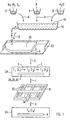
- the storage container 2 there is magnesium aluminate (MgAl 2 O 4 ) ("magnesium aluminate” is also referred to as spinel and has an octahedral crystal structure).
- the spinel is suitable as a ceramic material for an insulating component 8 in a high-temperature fuel cell 10 (see FIG. 2) if the composite printed circuit boards 12, 14 of the high-temperature fuel cell 10 to be joined are made of a chromium-based alloy (a chromium-based alloy is an alloy that Main component contains chromium (Cr)).
- the storage container 4 contains a water-soluble binder and the storage container 6 water (H 2 O) for producing a dispersion.
- a first step A about 90% by weight of the spinel from the storage container 2 and about 10% by weight of the binder from the storage container 4 are added in portions in a vessel 16 with the addition of water (H 2 O) from the storage container 6 a dispersion 18 implemented.
- a second step B the dispersion 18 (also called slip) to form a water-containing layer 20 potted on a suitable shaped base 22.
- the aqueous layer 18 has a thickness d between 500 and 800 ⁇ m. By an approximately constant thickness d of the layer To ensure 20, this can be done by machining (for example with a knife).
- the water-containing layer 20 is converted in a third step C at a temperature T 1 between 80 and 140 ° C. in an oven 24 for a time t 1 between 2 and 10 hours to a rubber-like layer 24 (which is often also referred to as green film) .
- a fourth step D the binder is burned out in the oven 24 at a temperature T 2 between 200 and 600 ° C. for a time t 2 between 1 and 4 hours. A binder-free layer 28 is obtained.
- the binder-free layer 28 likewise becomes a solidified layer 30 in the oven 24 at a temperature T 3 between 1400 and 1600 ° C. for a time period t 3 of at most 60 hours (the state of the solidified layer 30 is also known as White ceramics) implemented.
- the solidified layer 30 already has a porosity of less than 20%. It is in the ideal condition for shaping processing.
- a sixth step F the solidified layer is now 30 processed into insulating component 8.
- the solidified layer 30 becomes mechanical (e.g. processed by milling or drilling) or by a laser.
- This treatment gives the insulating component 8 already approximate their final shape (i.e. also with regard to their linear expansion).
- This editing feedthroughs 32 into the insulating component for feeding of resources and openings 34 for positioning of electrolyte electrode units incorporated.
- Processing for insulating component 8 after the fifth Solidification step E proves to be very advantageous, since the micro cracks that may occur during processing due to the structure of the porous inhomogeneities in solidified layer 30 ends. Unwanted cracks are largely avoided.
- a seventh step G (the last step of the method), the already solidified insulating component 8 is densely sintered, that is to say hardened again for its use.
- the sealing sintering is preferably carried out at a temperature T 4 between 1500 and 1800 ° C. for a time t 4 of approximately 60 hours.
- the insulating component shows 8 their final shape. Changes in linear expansion the insulating component 8 during the sealing sintering can be taken into account in the sixth step (F) become.
- a MgO / Al 2 O 3 mixture is used as the ceramic material for producing the insulating component 8.
- a composition of the mixture in which approximately 63% by weight of magnesium oxide (MgO) and 37% by weight of aluminum oxide (Al 2 O 3 ) are selected is particularly suitable.
- the insulating component 8 is the insulating component 8 between the two composite circuit boards to be joined 12,14 arranged.
- the bushings 32 and the breakthroughs 34 of the insulating component 8 from FIG. 1 are not visible.
- the manufactured according to the method shown in FIG 1 insulating component 8 is over the vitreous Layers 36, 38 coupled to the composite printed circuit boards 12 and 14.
- the composite printed circuit boards 12, 14 contain a chromium-based alloy and the insulating component 8 consists of the spinel.
- the insulating layer 36.38 is the insulating Layer 8 with the composite circuit boards 12, 14 integrally and connected in a gas-insulating manner.
- the glassy Layers 36, 38 preferably consist of an alkali-free one Glass solder.
- the insulating component 8 can be the insulating component 8 according to the method shown in FIG 1 in the predetermined Thickness can be produced.
- the procedure is therefore special for the production of high temperature fuel cells suitable.
Landscapes
- Engineering & Computer Science (AREA)
- Chemical & Material Sciences (AREA)
- Manufacturing & Machinery (AREA)
- Ceramic Engineering (AREA)
- Materials Engineering (AREA)
- Structural Engineering (AREA)
- Organic Chemistry (AREA)
- Life Sciences & Earth Sciences (AREA)
- Inorganic Chemistry (AREA)
- Sustainable Development (AREA)
- Sustainable Energy (AREA)
- Chemical Kinetics & Catalysis (AREA)
- Electrochemistry (AREA)
- General Chemical & Material Sciences (AREA)
- Fuel Cell (AREA)
- Glass Compositions (AREA)
Description
- FIG 1
- die Abfolge eines Verfahrensbeispiels der Erfindung zum Herstellen einer isolierenden Komponente aus einem keramischen Werkstoff für eine Hochtemperatur-Brennstoffzelle in schematischer Darstellung und
- FIG 2
- einen Ausschnitt aus einer Hochtemperatur-Brennstoffzelle in schematischer Darstellung.
Claims (12)
- Verfahren zum Herstellen einer isolierenden Komponente (8) aus einem keramischen Werkstoff für eine Hochtemperatur-Brennstoffzelle (10) mit folgenden Schritten:In einem ersten Schritt (A) wird ein keramischer Werkstoff durch Naßaufbereiten mit einem wasserlöslichen Bindemittel in eine Dispersion umgesetzt,in einem zweiten Schritt (B) wird die Dispersion zu einer wasserhaltigen Schicht (20) vergossen,in einem dritten Schritt (C) wird die wasserhaltige Schicht (20) bei erhöhter Temperatur zu einer gummiartigen Schicht (26) umgesetzt,in einem vierten Schritt (D) wird das Bindemittel bei erhöhter Temperatur aus der gummiartigen Schicht (26) ausgebrannt,in einem fünften Schritt (E) wird die ausgebrannte Schicht (28) bei erhöhter Temperatur verfestigt,in einem sechsten und siebten Schritt (F,G) wird die verfestigte Schicht (30) entsprechend den Abmessungen der isolierenden Komponente (8) bearbeitet und dichtgesintert.
- Verfahren nach Anspruch 1,
gekennzeichnet durch eine Dicke d zwischen 500 und 800 µm für die wasserhaltige Schicht (20). - Verfahren nach Anspruch 1 oder 2,
dadurch gekennzeichnet, daß die Dispersion im zweiten Schritt (B) in einer Form vergossen wird. - Verfahren nach einem der Ansprüche 1 bis 3,
dadurch gekennzeichnet, daß im dritten Schritt (C) die Umsetzung bei einer Temperatur T1 zwischen 80 und 140 °C durchgeführt wird. - Verfahren nach einem der vorhergehenden Ansprüche,
gekennzeichnet durch eine Zeitdauer t1 zwischen 2 und 10 Stunden für den dritten Schritt (C). - Verfahren nach einem der vorhergehenden Ansprüche,
dadurch gekennzeichnet, daß im vierten Schritt (D) des Bindemittels bei einer Temperatur T2 zwischen 200 und 600 °C ausgebrannt wird. - Verfahren nach einem der vorhergehenden Ansprüche,
gekennzeichnet durch eine Zeitdauer t2 zwischen 1 und 4 Stunden für den vierten Schritt (D). - Verfahren nach einem der vorhergehenden Ansprüche,
dadurch gekennzeichnet, daß im fünften Schritt (E) die Verfestigung bei einer Temperatur T3 zwischen 1400 und 1600 °C durchgeführt wird. - Verfahren nach einem der vorhergehenden Ansprüche,
gekennzeichnet durch eine Zeitdauer t3 von höchstens 60 Stunden für den fünften Schritt (E). - Verfahren nach einem der vorhergehenden Ansprüche,
dadurch gekennzeichnet, daß im siebenten Schritt (G) die Dichtsinterung bei einer Temperatur T4 zwischen 1500 und 1800 °C durchgeführt wird. - Verfahren nach einem der vorhergehenden Ansprüche,
gekennzeichnet durch eine Zeitdauer t4 von höchstens 60 Stunden für den siebenten Schritt (G). - Hochtemperatur-Brennstoffzelle (10) mit einer nach einem der Ansprüche 1 bis 11 hergestellten isolierenden Komponente (8).
Priority Applications (7)
| Application Number | Priority Date | Filing Date | Title |
|---|---|---|---|
| EP97114006A EP0897196B1 (de) | 1997-08-13 | 1997-08-13 | Verfahren zum Herstellen einer isolierenden Komponente für eine Hochtemperatur-Brennstoffzelle und Hochtemperatur-Brennstoffzelle |
| AT97114006T ATE209399T1 (de) | 1997-08-13 | 1997-08-13 | Verfahren zum herstellen einer isolierenden komponente für eine hochtemperatur- brennstoffzelle und hochtemperatur- brennstoffzelle |
| DE59706045T DE59706045D1 (de) | 1997-08-13 | 1997-08-13 | Verfahren zum Herstellen einer isolierenden Komponente für eine Hochtemperatur-Brennstoffzelle und Hochtemperatur-Brennstoffzelle |
| CA002244671A CA2244671A1 (en) | 1997-08-13 | 1998-08-11 | Process for the production of an insulating component for a high temperature fuel cell, and high temperature fuel cell |
| AU79940/98A AU731410B2 (en) | 1997-08-13 | 1998-08-12 | Process for the production of an insulating component for a high temperature fuel cell, and high temperature fuel cell |
| JP10228304A JPH11135138A (ja) | 1997-08-13 | 1998-08-12 | 高温燃料電池の絶縁構成部品の製造方法及び高温燃料電池 |
| US09/133,702 US6218037B1 (en) | 1997-08-13 | 1998-08-13 | Process for the production of an insulating component for a high temperature fuel cell, and high temperature fuel cell |
Applications Claiming Priority (1)
| Application Number | Priority Date | Filing Date | Title |
|---|---|---|---|
| EP97114006A EP0897196B1 (de) | 1997-08-13 | 1997-08-13 | Verfahren zum Herstellen einer isolierenden Komponente für eine Hochtemperatur-Brennstoffzelle und Hochtemperatur-Brennstoffzelle |
Publications (2)
| Publication Number | Publication Date |
|---|---|
| EP0897196A1 EP0897196A1 (de) | 1999-02-17 |
| EP0897196B1 true EP0897196B1 (de) | 2001-11-21 |
Family
ID=8227209
Family Applications (1)
| Application Number | Title | Priority Date | Filing Date |
|---|---|---|---|
| EP97114006A Expired - Lifetime EP0897196B1 (de) | 1997-08-13 | 1997-08-13 | Verfahren zum Herstellen einer isolierenden Komponente für eine Hochtemperatur-Brennstoffzelle und Hochtemperatur-Brennstoffzelle |
Country Status (7)
| Country | Link |
|---|---|
| US (1) | US6218037B1 (de) |
| EP (1) | EP0897196B1 (de) |
| JP (1) | JPH11135138A (de) |
| AT (1) | ATE209399T1 (de) |
| AU (1) | AU731410B2 (de) |
| CA (1) | CA2244671A1 (de) |
| DE (1) | DE59706045D1 (de) |
Families Citing this family (3)
| Publication number | Priority date | Publication date | Assignee | Title |
|---|---|---|---|---|
| YU88103A (sh) * | 2002-05-14 | 2006-08-17 | H.Lundbeck A/S. | Lecenje adhd |
| DE102006058335A1 (de) * | 2006-12-11 | 2008-06-12 | Staxera Gmbh | Brennstoffzellenstapel und Dichtung für einen Brennstoffzellenstapel sowie deren Herstellungsverfahren |
| DE102020128557A1 (de) | 2020-10-30 | 2022-05-05 | Audi Aktiengesellschaft | Brennstoffzellenstapel mit Gussmaterial und Verfahren zum Herstellen eines Brennstoffzellenstapels |
Family Cites Families (7)
| Publication number | Priority date | Publication date | Assignee | Title |
|---|---|---|---|---|
| DE4224906A1 (de) * | 1992-07-28 | 1994-02-03 | Hoechst Ceram Tec Ag | Keramischer Werkstoff, der zu einem Formteil mit hohem thermischen Ausdehnungskoeffizienten gesintert werden kann |
| DE4233518C1 (de) * | 1992-10-06 | 1994-08-25 | Hoechst Ag | Wäßrige Gießmasse zur Herstellung von grünen Keramikfolien und daraus hergestellte Keramikformteile |
| US5834108A (en) * | 1992-12-29 | 1998-11-10 | Toshiba Ceramics Co., Ltd. | Multi-layered ceramic porous body |
| US5942348A (en) * | 1994-12-01 | 1999-08-24 | Siemens Aktiengesellschaft | Fuel cell with ceramic-coated bipolar plates and a process for producing the fuel cell |
| JP3604848B2 (ja) * | 1996-01-18 | 2004-12-22 | 日本碍子株式会社 | 電気化学セル用積層焼結体、電気化学セルおよび電気化学セル用積層焼結体の製造方法 |
| DE19608727C1 (de) * | 1996-03-06 | 1997-06-19 | Siemens Ag | Elektrisch isolierende Schicht zum Verbinden von elektrisch leitenden Bauelementen einer Hochtemperatur-Brennstoffzelle |
| US5868918A (en) * | 1996-09-26 | 1999-02-09 | Air Products And Chemicals, Inc. | Method for separating oxygen from an oxygen-containing gas |
-
1997
- 1997-08-13 DE DE59706045T patent/DE59706045D1/de not_active Expired - Fee Related
- 1997-08-13 EP EP97114006A patent/EP0897196B1/de not_active Expired - Lifetime
- 1997-08-13 AT AT97114006T patent/ATE209399T1/de not_active IP Right Cessation
-
1998
- 1998-08-11 CA CA002244671A patent/CA2244671A1/en not_active Abandoned
- 1998-08-12 AU AU79940/98A patent/AU731410B2/en not_active Ceased
- 1998-08-12 JP JP10228304A patent/JPH11135138A/ja not_active Withdrawn
- 1998-08-13 US US09/133,702 patent/US6218037B1/en not_active Expired - Fee Related
Also Published As
| Publication number | Publication date |
|---|---|
| ATE209399T1 (de) | 2001-12-15 |
| AU7994098A (en) | 1999-02-25 |
| US6218037B1 (en) | 2001-04-17 |
| EP0897196A1 (de) | 1999-02-17 |
| DE59706045D1 (de) | 2002-02-21 |
| AU731410B2 (en) | 2001-03-29 |
| JPH11135138A (ja) | 1999-05-21 |
| CA2244671A1 (en) | 1999-02-13 |
Similar Documents
| Publication | Publication Date | Title |
|---|---|---|
| DE69213488T2 (de) | Verfahren zur Herstellung einer Lanthanchromitschicht und Verfahren zur Herstellung einer Zellenverbindungsschicht für Festelektrolytbrennstoffzellen | |
| EP1498969B1 (de) | Brennstoffzelleneinheit, Brennstoffzellenblockverbund und Verfahren zum Herstellen eines Brennstoffzellenblockverbunds | |
| DE69612659T2 (de) | Festoxidbrennstoffzellen mit spezifischen elektrodenschichten | |
| DE10324396B4 (de) | Brennstoffzelle und Brennstoffzellenanordnung | |
| DE69701211T2 (de) | Flacher Festelektrolyt-Brennstoffzellenstapel mit Polarisationselektroden und versetzten Dichtungen, als Sauerstoffpumpe arbeitend | |
| EP0452737A1 (de) | Brennstoffzellenanordnung und Verfahren zu deren Herstellung | |
| DE3922673A1 (de) | Hochtemperaturbrennstoffzelle | |
| DE2746172A1 (de) | Verbund von elektrochemischen festelektrolytzellen | |
| DE2753198A1 (de) | Magnetohydrodynamische elektrode | |
| EP0395975A1 (de) | Brennstoffzellenanordnung | |
| EP0651698B1 (de) | Verbundsysteme mit mindestens zwei anorganischen keramischen schichten und verfahren zu deren herstellung | |
| DE10108438A1 (de) | Oxidionenleiter, Herstellungsmethode dafür und ihn verwendende Brennstoffzelle | |
| DE102007018610A1 (de) | Keramischer Werkstoff mit einer Zusammensetzung, die auf einen durch einen metallischen Werkstoff vorgegebenen Wärmeausdehnungskoeffizient abgestimmt ist | |
| WO2000008701A2 (de) | Verfahren zur herstellung einer hochtemperatur-brennstoffzelle | |
| EP0897196B1 (de) | Verfahren zum Herstellen einer isolierenden Komponente für eine Hochtemperatur-Brennstoffzelle und Hochtemperatur-Brennstoffzelle | |
| EP1246283A2 (de) | Elektrisch isolierende Abstandshalter/Dichtungsanordnung | |
| DE10358457B4 (de) | Distanzhalterelement für einen Brennstoffzellenstapel und Brennstoffzelleneinheit mit einem solchen Distanzhalterelement | |
| DE19908213A1 (de) | Basisrohr für eine Brennstoffzelle | |
| DE3116786C2 (de) | Homogener Siliciumcarbid-Formkörper und Verfahren zu seiner Herstellung | |
| DE2824408C3 (de) | Verfahren zur Herstellung eines elektronisch | |
| EP0499935A1 (de) | Festelektrolyt-Brennstoffzellenanordnung | |
| EP1340282B1 (de) | Brennstoffzellenanordnung | |
| DE19730003B4 (de) | Elektrisch leitfähiges Hochtemperaturbrennstoffzellenbauteil und Verwendung eines Metall-Keramik-Verbundwerkstoffs zur Herstellung eines Hochtemperaturbrennstoffzellenbauteils | |
| DE19643157C1 (de) | Verfahren zur Herstellung eines Chrom-Werkstoffes | |
| DE19643156C1 (de) | Verfahren zur Herstellung eines Chrom-Werkstoffs |
Legal Events
| Date | Code | Title | Description |
|---|---|---|---|
| PUAI | Public reference made under article 153(3) epc to a published international application that has entered the european phase |
Free format text: ORIGINAL CODE: 0009012 |
|
| AK | Designated contracting states |
Kind code of ref document: A1 Designated state(s): AT BE CH DE DK ES GB IT LI NL SE |
|
| 17P | Request for examination filed |
Effective date: 19990319 |
|
| AKX | Designation fees paid |
Free format text: AT BE CH DE DK ES GB IT LI NL SE |
|
| 17Q | First examination report despatched |
Effective date: 20000118 |
|
| GRAG | Despatch of communication of intention to grant |
Free format text: ORIGINAL CODE: EPIDOS AGRA |
|
| GRAG | Despatch of communication of intention to grant |
Free format text: ORIGINAL CODE: EPIDOS AGRA |
|
| GRAH | Despatch of communication of intention to grant a patent |
Free format text: ORIGINAL CODE: EPIDOS IGRA |
|
| GRAH | Despatch of communication of intention to grant a patent |
Free format text: ORIGINAL CODE: EPIDOS IGRA |
|
| GRAA | (expected) grant |
Free format text: ORIGINAL CODE: 0009210 |
|
| AK | Designated contracting states |
Kind code of ref document: B1 Designated state(s): AT BE CH DE DK ES GB IT LI NL SE |
|
| PG25 | Lapsed in a contracting state [announced via postgrant information from national office to epo] |
Ref country code: NL Free format text: LAPSE BECAUSE OF FAILURE TO SUBMIT A TRANSLATION OF THE DESCRIPTION OR TO PAY THE FEE WITHIN THE PRESCRIBED TIME-LIMIT Effective date: 20011121 Ref country code: IT Free format text: LAPSE BECAUSE OF FAILURE TO SUBMIT A TRANSLATION OF THE DESCRIPTION OR TO PAY THE FEE WITHIN THE PRE;WARNING: LAPSES OF ITALIAN PATENTS WITH EFFECTIVE DATE BEFORE 2007 MAY HAVE OCCURRED AT ANY TIME BEFORE 2007. THE CORRECT EFFECTIVE DATE MAY BE DIFFERENT FROM THE ONE RECORDED.SCRIBED TIME-LIMIT Effective date: 20011121 |
|
| REF | Corresponds to: |
Ref document number: 209399 Country of ref document: AT Date of ref document: 20011215 Kind code of ref document: T |
|
| REG | Reference to a national code |
Ref country code: CH Ref legal event code: EP |
|
| REG | Reference to a national code |
Ref country code: GB Ref legal event code: IF02 |
|
| PG25 | Lapsed in a contracting state [announced via postgrant information from national office to epo] |
Ref country code: SE Free format text: LAPSE BECAUSE OF FAILURE TO SUBMIT A TRANSLATION OF THE DESCRIPTION OR TO PAY THE FEE WITHIN THE PRESCRIBED TIME-LIMIT Effective date: 20020221 Ref country code: DK Free format text: LAPSE BECAUSE OF FAILURE TO SUBMIT A TRANSLATION OF THE DESCRIPTION OR TO PAY THE FEE WITHIN THE PRESCRIBED TIME-LIMIT Effective date: 20020221 |
|
| REF | Corresponds to: |
Ref document number: 59706045 Country of ref document: DE Date of ref document: 20020221 |
|
| GBT | Gb: translation of ep patent filed (gb section 77(6)(a)/1977) |
Effective date: 20020216 |
|
| NLV1 | Nl: lapsed or annulled due to failure to fulfill the requirements of art. 29p and 29m of the patents act | ||
| PG25 | Lapsed in a contracting state [announced via postgrant information from national office to epo] |
Ref country code: ES Free format text: LAPSE BECAUSE OF FAILURE TO SUBMIT A TRANSLATION OF THE DESCRIPTION OR TO PAY THE FEE WITHIN THE PRESCRIBED TIME-LIMIT Effective date: 20020530 |
|
| PGFP | Annual fee paid to national office [announced via postgrant information from national office to epo] |
Ref country code: AT Payment date: 20020717 Year of fee payment: 6 |
|
| PG25 | Lapsed in a contracting state [announced via postgrant information from national office to epo] |
Ref country code: GB Free format text: LAPSE BECAUSE OF NON-PAYMENT OF DUE FEES Effective date: 20020813 |
|
| PG25 | Lapsed in a contracting state [announced via postgrant information from national office to epo] |
Ref country code: LI Free format text: LAPSE BECAUSE OF NON-PAYMENT OF DUE FEES Effective date: 20020831 Ref country code: CH Free format text: LAPSE BECAUSE OF NON-PAYMENT OF DUE FEES Effective date: 20020831 Ref country code: BE Free format text: LAPSE BECAUSE OF NON-PAYMENT OF DUE FEES Effective date: 20020831 |
|
| PLBE | No opposition filed within time limit |
Free format text: ORIGINAL CODE: 0009261 |
|
| STAA | Information on the status of an ep patent application or granted ep patent |
Free format text: STATUS: NO OPPOSITION FILED WITHIN TIME LIMIT |
|
| 26N | No opposition filed | ||
| BERE | Be: lapsed |
Owner name: *SIEMENS A.G. Effective date: 20020831 |
|
| PG25 | Lapsed in a contracting state [announced via postgrant information from national office to epo] |
Ref country code: DE Free format text: LAPSE BECAUSE OF NON-PAYMENT OF DUE FEES Effective date: 20030301 |
|
| GBPC | Gb: european patent ceased through non-payment of renewal fee |
Effective date: 20020813 |
|
| REG | Reference to a national code |
Ref country code: CH Ref legal event code: PL |
|
| PG25 | Lapsed in a contracting state [announced via postgrant information from national office to epo] |
Ref country code: AT Free format text: LAPSE BECAUSE OF NON-PAYMENT OF DUE FEES Effective date: 20030813 |