EP0897310B1 - Quetschventil zum absperren eines schlauchs - Google Patents
Quetschventil zum absperren eines schlauchs Download PDFInfo
- Publication number
- EP0897310B1 EP0897310B1 EP97921912A EP97921912A EP0897310B1 EP 0897310 B1 EP0897310 B1 EP 0897310B1 EP 97921912 A EP97921912 A EP 97921912A EP 97921912 A EP97921912 A EP 97921912A EP 0897310 B1 EP0897310 B1 EP 0897310B1
- Authority
- EP
- European Patent Office
- Prior art keywords
- closure piece
- hose
- plate
- slot
- axis
- Prior art date
- Legal status (The legal status is an assumption and is not a legal conclusion. Google has not performed a legal analysis and makes no representation as to the accuracy of the status listed.)
- Expired - Lifetime
Links
- 230000002572 peristaltic effect Effects 0.000 claims description 25
- 238000006073 displacement reaction Methods 0.000 claims description 5
- 230000000712 assembly Effects 0.000 claims 1
- 238000000429 assembly Methods 0.000 claims 1
- 230000000295 complement effect Effects 0.000 claims 1
- 239000007788 liquid Substances 0.000 description 9
- 229920000297 Rayon Polymers 0.000 description 3
- 238000012550 audit Methods 0.000 description 3
- 239000002964 rayon Substances 0.000 description 3
- 238000001802 infusion Methods 0.000 description 2
- 238000007789 sealing Methods 0.000 description 2
- 241001080024 Telles Species 0.000 description 1
- 230000015572 biosynthetic process Effects 0.000 description 1
- 210000004027 cell Anatomy 0.000 description 1
- 239000003795 chemical substances by application Substances 0.000 description 1
- 230000006835 compression Effects 0.000 description 1
- 238000007906 compression Methods 0.000 description 1
- 238000010586 diagram Methods 0.000 description 1
- 239000003814 drug Substances 0.000 description 1
- 229940079593 drug Drugs 0.000 description 1
- 230000000694 effects Effects 0.000 description 1
- 230000005489 elastic deformation Effects 0.000 description 1
- 230000005484 gravity Effects 0.000 description 1
- 238000012423 maintenance Methods 0.000 description 1
- 210000000056 organ Anatomy 0.000 description 1
Images




Classifications
-
- A—HUMAN NECESSITIES
- A61—MEDICAL OR VETERINARY SCIENCE; HYGIENE
- A61M—DEVICES FOR INTRODUCING MEDIA INTO, OR ONTO, THE BODY; DEVICES FOR TRANSDUCING BODY MEDIA OR FOR TAKING MEDIA FROM THE BODY; DEVICES FOR PRODUCING OR ENDING SLEEP OR STUPOR
- A61M39/00—Tubes, tube connectors, tube couplings, valves, access sites or the like, specially adapted for medical use
- A61M39/22—Valves or arrangement of valves
- A61M39/28—Clamping means for squeezing flexible tubes, e.g. roller clamps
- A61M39/286—Wedge clamps, e.g. roller clamps with inclined guides
- A61M39/287—Wedge formed by a slot having varying width, e.g. slide clamps
Definitions
- the present invention relates to a shutter device by pinching of a flexible tube.
- the invention relates to a device mechanical which allows it to be closed completely by pinching, so to interrupt the circulation of a liquid, a tube or a tubing flexible, in particular of the type used in the medical field for administering drugs or other agents to patients similar by infusion.
- Such a closure device by pinching a flexible tube is usable in the medical field, in particular in connection with a peristaltic pump allowing circulation under pressure of liquid between a liquid storage pocket and a line of infusion.
- peristaltic pumps are small and it is therefore interesting that the shutter device is itself weak dimension and adapted to the structure of such a peristaltic pump.
- Such peristaltic pumps are notably described in the Patent application WO-95/31643 published on November 23, 1995 in name of depositor.
- Such pump devices are constituted essentially a pump module itself or cassette which has pressure rollers cooperating with a tube member deformable which can be removably inserted in a block engine, this engine block for driving in rotation of compression rollers and therefore the operation of the pump peristaltic.
- the pump rollers no longer perform their function local sealing on the tube element and a circulation of the liquid to through the pump and therefore in the associated tubes can occur by gravity. It is therefore, in this particular case, strictly necessary to provide, associated with this peristaltic pump, a mechanical device obturation of the tube to avoid any accident related to a bad handling of the cassette by hospital staff or the patient.
- An object of the present invention is to provide a device obturation by pinching a flexible tube, in particular but not exclusively associated with a peristaltic pump which allows a effective and total interruption of the flow, while preferably compatible with the peristaltic pump.
- the device also comprises fixed means to substantially immobilize said tube in the direction of displacement of said closure piece. More preferably, the device comprises means for locking said part shutter in its second position.
- the device for plugging the outlet tube of a peristaltic pump which includes a housing, a first cylindrical nozzle for connection to a tube inlet and a second nozzle for connection to said outlet tube, said nozzles having substantially parallel axes, is characterized by that said device comprises a first assembly mounted fixed on said second nozzle for defining said holding means, said locking means and part of said guide means in rotation and a second assembly mounted pivoting around said first nozzle for defining said arm, said closure piece, a part of the rotating guide means and the means for moving in rotation said closure member.
- the mode of the shutter device is particularly good suitable for use with a peristaltic pump since the device is reduced to two very simple parts using one of the nozzles of the peristaltic pump as a fixing member for one of the parts of the obturator and the other peristaltic pump nozzle as pivot axis of the second movable part of the device shutter.
- FIG. 1 shows in a simplified way the assembly of the two parts of the closure device on a peristaltic pump 10.
- the housing 12 of the pump peristaltic with its two inlet and outlet nozzles 14 respectively 16 on which one comes to fix the inlet tubing 18 and the tubing of outlet 20.
- Nozzles 14 and 16 each have a cylindrical shape and have axes XX 'and YY' which are parallel to each other.
- the closure device which carries the general reference 22 consists of two parts, on the one hand, a fixed part 24 essentially used to hold the tube 20 to be closed and in guiding the second part 26 of the shutter device which, it essentially consists of a pivoting piece for closing the tube.
- the part 26 comprising the obturation piece is pivotally mounted around the axis YY ', by through a cylindrical sleeve 28, while the part 24 is fixed mounted on the nozzle 16 also by means of a sleeve cylindrical 30.
- Figure 1 is simply intended to expose the mounting the device and therefore does not represent it in detail.
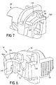
- This plate is provided with a circular orifice 34 whose diameter is substantially equal to the external diameter of the tube to be closed.
- a holding member of the tube 36 which has substantially the shape of an arc of a circle.
- This piece is connected at its two ends 36a and 36b to the two ends of the plate 32 by means of connection portions 38 and 40.
- connection portions 38 and 40 there is a free space between the plate 32, the holding member 36 and the connection portions 38 and 40 which, as will be explained subsequently, used for the passage of the closure piece.
- connection portions 38 and 40 are provided each in their inner face with a guide groove respectively 42 and 44 which also have an arc shape centered on the axis YY ' from the other nozzle of the peristaltic pump.
- the groove 44 of the connecting portion 38 is provided a lug 46 whose function will be explained later.
- the part in an arc 36 of the holding member is provided with an inclined slot 48 thus defining two parts 36c and 36d of the holding member 36.
- the portion of connection 38 is extended beyond plate 32 by a actuating tongue 50, this tongue 50 extending exactly the connection portion 38.
- the plate 32 is in fact provided with a recess 52 which thus defines a vertical portion of the plate 54 on which the portion of connection 38 and the tongue 50.
- the recess 52 by pressing on the tongue 50, it can be caused by elastic deformation a pivoting of the vertical part 54 of the plate, which causes a corresponding pivoting of the portion of connection 38 for reasons which will be explained later.
- this pivoting of the portion of connection 38 is made possible by the presence of the inclined slot 48 provided in the holding member 36.
- the holding member 36 is disposed so that its underside 36 'is substantially in contact from the upper edge of the tube to be closed.
- connection piece 38 It differs from the holding part 24 as regards the realization of the holding member 36 and that of the rib 44 formed in connection piece 38.
- the new holding member 136 is only connected by its end 136a to the connection portion 40. Its other end 136b is free.
- the holding member 136 is therefore mounted in overhang.
- it comprises stiffening ribs 135 and 137. It performs exactly the same function as organ 36 in preventing lifting of the tube 20.
- the guide groove 44 in FIG. 5 is replaced by the groove 44 'which is defined by the return 140 of the connecting piece 138 and by a rib 142 projecting from the front face of the plate 32 in look back 140. In this rib 44 ', there is the latch 46.
- connection 138 can pivot freely around part 54 of the plate 32 under the effect of the actuation of the tongue 50 since this connecting piece is not connected to the holding member 136.
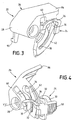
- FIGS. 2 and 3 we will describe the movable shutter part 26 of the device shutter which can be used with both embodiments of the holding part 24 or 24 '.
- This part 26 is essentially constituted by the sleeve 28 which is pivotally mounted on the nozzle 14.
- the part shutter 26 can therefore pivot around the axis YY 'which is parallel to the axis XX 'of the tubing to be closed and, more precisely, this part can pivot around this axis substantially in a plane obviously perpendicular to this axis and therefore perpendicular to the axis of the tube to seal.
- the part 26 is essentially constituted by a portion 60 constituting an arm which is, at its first end 60a, connected to the sleeve 28 and which is, at its second end 60b, connected to a shutter piece 62.
- This shutter piece 62 has the general shape of an arc of a circle limited by an internal circular edge 64 and by a outer circular edge 66, the closure piece 62 having a first free end 68 and a second end 69 connected to the end 60b of the arm 60.
- the circular edges 64 and 66 of the closure piece 62 are concentric arcs whose common center is point O arranged on the pivot axis YY '.
- the plate in the shape of an arc forming the part shutter 62 is provided in its middle part with a slot 70.
- This slot has a first end 72 close to the end 68 of the part 62 and a second end 74.
- the slot 70 is extended by a recess 76 of circular shape preferably whose diameter is slightly greater than the external diameter of the tube to be closed.
- the end 74 of slot 70 connects tangentially in zone 78 to the circular recess 76.
- the slot 70 in its current part, has a width e which is substantially equal or preferably slightly less than twice the thickness of the wall of the tube to be closed.
- the middle line of slot 70 and the center of recess 76 are arranged on a circular arc of radius R and centered on the axis YY '.
- the lips of slot 70 preferably have, in a cutting plane perpendicular to the plane of the part 62, a rounded shape or the like or at least a form without a singular point to avoid risks of tube damage.
- Figure 2 also shows that the edges 64 and 66 of the part shutter 62 are provided with ribs in the shape of an arc of a circle respectively referenced 80 and 82 which cooperate with the grooves 44 or 44 'and 42 formed in the holding portions of the part of support 24.
- this part is further guided by the cooperation of the ribs 80, 82 with the grooves 42, 44 or 44 '. She has therefore a displacement which occurs in a rigorously plane perpendicular to the axis XX 'of the tube.
- the rib 82 has a hollow forming discontinuity 84 which is long enough to allow the engagement of the lug 46.
- the hollow 84 is arranged in such a way that the lug 46 enters the recess 84 when the closure piece 62 is in its position shown in Figure 4, that is to say in its shutter position, thus locking the part shutter in its shutter position.
- the rib 82 has a thickness which increases when approaching the end 68 of the part 62. This effectively makes it possible to obtain the locking thanks to the possibility of pivoting the portion of connection 38 or 138.
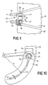
- the shutter portion 26 is in the position shown in Figures 2 and 3, i.e. the outlet tube 20 is free and passes through the orifice 34, the recess 76 of the closure piece and the holding 36 or 136.
- the control plate 86 integral of the arm 60. By lifting this plate 86, the movement is caused pivoting up the shutter member.
- the tube being held up by the wall of the orifice 34 and by the piece of holding 36 or 136, lifting the sealing piece 62 causes the lower part of the tube to engage in part 78 flared from the slot 70.
- the locking pin 46 enters the hollow 84 of the obturation piece thus ensuring the maintenance of the obturation of the tube.
- the shutter part 26 has a hook 90 on its sleeve 28 at its lower part protruding from the sleeve.
- the hook 90 cooperates with a conjugate part (not shown) of the casing 10 'of the associated motor with the peristaltic pump 10, it is therefore impossible to extract the cassette of the peristaltic pump 10 when the shutter is in the position opened.
- the closure piece 62 has been brought in the position shown in Figure 4, i.e. the position shutter, position in which the part 62 is locked on the part 24 of the closure device, the hook 90 is released and it is therefore free to remove cassette 10 from the peristaltic pump out of the motor housing.
Landscapes
- Health & Medical Sciences (AREA)
- Heart & Thoracic Surgery (AREA)
- Pulmonology (AREA)
- Engineering & Computer Science (AREA)
- Anesthesiology (AREA)
- Biomedical Technology (AREA)
- Hematology (AREA)
- Life Sciences & Earth Sciences (AREA)
- Animal Behavior & Ethology (AREA)
- General Health & Medical Sciences (AREA)
- Public Health (AREA)
- Veterinary Medicine (AREA)
- Infusion, Injection, And Reservoir Apparatuses (AREA)
- Reciprocating Pumps (AREA)
Claims (15)
- Vorrichtung zum Verschließen eines Schlauchs (20) durch Quetschen, wobei der zu verschließende Bereich des Schlauchs eine Achse XX' aufweist, die ein bewegliches Verschließteil (62) umfasst, das einen Spalt (70) aufweist, wobei der Spalt ein erstes Ende (72) und ein zweites Ende (74) aufweist, wobei das zweite Ende mit einer Erweiterung (76) in Verbindung steht, deren Abmessungen mindestens gleich denen des Querschnitts des Schlauchs sind, wobei der Spalt in der Nähe seines ersten Endes eine Breite hat, bei der das vollständige Zuquetschen des Schlauchs bewirkt werden kann, und wobei das zweite Ende des Spalts eine Breite hat, die sich langsam erhöht, um an die Erweiterung anzuschließen, wobei die Vorrichtung dadurch gekennzeichnet ist, dass der Spalt (70) die Form eines Kreisbogens mit dem Radius R hat, und dass sie ferner aufweist:Mittel, um eine bezogen auf den zu verschließenden Schlauch feste Drehachse (YY') festzulegen, die im Wesentlichen parallel zur Achse XX' des Schlauchs verläuft;Mittel (60, 42, 44, 44', 80, 82) zum Führen des Teils zum Verschließen um die Drehachse bei der Drehung derart, dass sich der Spalt im Ganzen in einem Kreis bewegt, dessen Radius gleich dem Radius R ist, und um die Drehachse zentriert ist und in einer zur Drehachse senkrechten Ebene angeordnet ist, wobei die Mittel einen Arm (60) aufweisen, von dem ein erstes Ende (60a) um die Drehachse schwenkbar befestigt ist, und von dem ein zweites Ende (60b) mit dem Verschließteil verbunden ist; undMittel (86) zum drehenden Bewegen des Teils (62) zum Verschließen zwischen einer ersten Stellung, bei der das Rohr die Erweiterung des Verschließstücks ungehindert durchquert, und einer zweiten Stellung, bei der der Schlauch im ersten Ende des Spalts gequetscht ist.
- Vorrichtung nach Anspruch 1, dadurch gekennzeichnet, dass sie ferner feste Mittel (24, 24') umfasst, um den Schlauch entsprechend der Bewegungsrichtung des Verschließteils merklich festzuhalten.
- Vorrichtung nach Anspruch 2, dadurch gekennzeichnet, dass sie ferner Mittel (50, 46, 84) zum Verriegeln des Verschließteils in seiner zweiten Stellung umfasst.
- Vorrichtung nach einem der Ansprüche 1 bis 3 zum Verschließen des Ausgangsrohrs (20) einer Quetschschlauchpumpe, welche ein Gehäuse (10), eine erste zylindrische Düse (14) zum Verbinden mit einem Eingangsrohr und eine zweite Düse (16) zum Verbinden mit dem Ausgangsrohr umfasst, wobei die Düsen im Wesentlichen parallel zueinander verlaufende Achsen aufweisen, dadurch gekennzeichnet, dass die Vorrichtung eine erste, fest an der zweiten Düse befestigte Einheit (24, 24') zum Festlegen der Haltemittel, die Verriegelungsmittel und einen Teil der Mittel zum Führen bei der Drehung und eine zweite, um die erste Düse schwenkbar befestigte Einheit (26) zum Festlegen des Arms, das Verschließteil und einen Teil der Mittel zum Führen bei der Drehung und die Mittel zum drehenden Verschieben des Verschließteils umfasst.
- Vorrichtung nach Anspruch 4, dadurch gekennzeichnet, dass das Verschließteil (62) aus einer Platte in Form eines Kreisbogens gebildet ist, der von einem inneren kreisförmigen Rand (64) und einem äußeren kreisförmigen Rand (66) begrenzt ist, und ein erstes Ende (68), das dem ersten Ende des Spalts (70) entspricht, und ein zweites Ende (69), das der Erweiterung (76) entspricht, umfasst, wobei das zweite Ende (60b) des Arms mit einem Ende des Verschließteils verbunden ist.
- Vorrichtung nach Anspruch 5, dadurch gekennzeichnet, dass die Haltemittel eine erste Platte (32) umfassen, die mit der zweiten Düse verbunden ist und mit einer Öffnung (34) versehen ist, deren Durchmesser etwas größer als der äußere Durchmesser des Schlauchs ist, und die in einer zur Achse des Schlauchs senkrechten Ebene angeordnet ist.
- Vorrichtung nach Anspruch 6, dadurch gekennzeichnet, dass die Mittel zum Halten ferner ein Halteteil (36) umfassen, das bezogen auf die Platte axial versetzt ist und mit der Platte derart verbunden ist, dass sich das Verschließteil (62) zwischen der Platte und dem Halteteil bewegen kann, wobei das Halteteil mit dem Schlauch (20) im Wesentlichen in Berührung steht und den Schlauch festhalten kann, wenn das Verschließteil von seiner ersten in seine zweite Stellung bewegt wird.
- Vorrichtung nach Anspruch 7, dadurch gekennzeichnet, dass das Halteteil (36) die Form eines Kreisbogens hat, dessen eines Ende mit einem ersten Verbindungsabschnitt (38) mit der Platte (32) verbunden ist, und dessen zweites Ende über einen zweiten Verbindungsabschnitt (40) mit der Platte verbunden ist.
- Vorrichtung nach Anspruch 8, dadurch gekennzeichnet, dass das Halteteil (36) zwischen seinem ersten und zweiten Ende einen Spalt (48) aufweist.
- Vorrichtung nach Anspruch 9, dadurch gekennzeichnet, dass die Haltemittel ferner ein Halteteil (136) umfassen, das bezogen auf die Platte axial versetzt ist und über eines seiner Enden mit der Platte verbunden ist, derart, dass sich das Verschließteil (62) zwischen der Platte und dem Halteteil bewegen kann, wobei das Halteteil mit dem Schlauch (20) im Wesentlichen in Berührung steht und den Schlauch festhalten kann, wenn das Verschließteil aus seiner ersten Stellung in seine zweite Stellung bewegt wird.
- Vorrichtung nach Anspruch 10, dadurch gekennzeichnet, dass das Halteteil die Form eines Teilkreisbogens hat, dessen eines Ende frei ist, und dessen anderes Ende über einen ersten Verbindungsabschnitt mit der Platte verbunden ist, und dass es ferner einen zweiten Verbindungsabschnitt umfasst, der mit der Platte in Verbindung steht und aus der Platte herausragt.
- Vorrichtung nach einem der Ansprüche 8 oder 11, dadurch gekennzeichnet, dass der Innen- und Außenrand des Verschließteils (62) mit Rippen (80, 82) versehen sind, die mit eine Nut (42, 44, 44') in Form eines Kreisbogens bildenden Mitteln zusammenwirken können, welche in jedem Verbindungsabschnitt der Haltemittel vorgesehen sind.
- Vorrichtung nach Anspruch 11, dadurch gekennzeichnet, dass die Verriegelungsmittel einen Vorsprung (46) umfassen, der in den eine Nut (44, 44') des zweiten Verbindungsabschnitts (38, 138) vorgesehen ist, die mit einer Vertiefung (84), die in der zu diesem Verschließteil zugehörigen Rippe (82) angeordnet ist, zusammenwirken kann, wobei der Verbindungsabschnitt (38, 138) durch eine Entriegelungszunge (50) verlängert ist, und wobei die Verbindung (54) zwischen einerseits dem Verbindungsabschnitt und der Zunge und andererseits einem Rand der Platte eine Schwenkachse des Verbindungsabschnitts bezüglich der Platte bilden, wobei die Betätigung der Zunge das zeitweilige Verschwenken des Verbindungsabschnitts ermöglicht, um das Austreten des Vorsprungs aus der Vertiefung zu ermöglichen.
- Vorrichtung nach einem der Ansprüche 3 bis 13 für eine Quetschschlauchpumpe (10), deren Gehäuse in abnehmbarer Weise in das Gehäuse (10') eines Mitführmotors eingreift, dadurch gekennzeichnet, dass die erste (24, 24') und zweite Einheit (26) jeweils über Hülsen (28, 30) an den Düsen (14, 16) befestigt sind, wobei die Hülse (28) der zweiten Einheit (26) schwenkbar an der zugehörigen Düse befestigt ist.
- Vorrichtung nach Anspruch 14, dadurch gekennzeichnet, dass die schwenkbar befestigte Hülse ein Verriegelungsteil (90) aufweist, das mit einem gekoppelten Teil des Gehäuses (10') zusammenwirken kann, wenn das Verschließteil (62) nicht in seiner zweiten Stellung ist.
Applications Claiming Priority (3)
| Application Number | Priority Date | Filing Date | Title |
|---|---|---|---|
| FR9605543A FR2748310A1 (fr) | 1996-05-03 | 1996-05-03 | Dispositif d'obturation par pincement d'un tube souple |
| FR9605543 | 1996-05-03 | ||
| PCT/FR1997/000771 WO1997041918A1 (fr) | 1996-05-03 | 1997-04-30 | Dispositf d'obturation par pincement d'un tube souple |
Publications (2)
| Publication Number | Publication Date |
|---|---|
| EP0897310A1 EP0897310A1 (de) | 1999-02-24 |
| EP0897310B1 true EP0897310B1 (de) | 2003-02-05 |
Family
ID=9491800
Family Applications (1)
| Application Number | Title | Priority Date | Filing Date |
|---|---|---|---|
| EP97921912A Expired - Lifetime EP0897310B1 (de) | 1996-05-03 | 1997-04-30 | Quetschventil zum absperren eines schlauchs |
Country Status (7)
| Country | Link |
|---|---|
| US (1) | US6364279B1 (de) |
| EP (1) | EP0897310B1 (de) |
| JP (1) | JP4156670B2 (de) |
| AU (1) | AU2780097A (de) |
| DE (1) | DE69718905T2 (de) |
| FR (1) | FR2748310A1 (de) |
| WO (1) | WO1997041918A1 (de) |
Families Citing this family (21)
| Publication number | Priority date | Publication date | Assignee | Title |
|---|---|---|---|---|
| US5853398A (en) * | 1997-12-19 | 1998-12-29 | Baxter International Inc. | Container with pivoting tube clamp |
| US7329248B2 (en) * | 2003-02-18 | 2008-02-12 | Medical Components, Inc. | Catheter sheath pinch clamp |
| EP1617888B1 (de) | 2003-04-23 | 2019-06-12 | Valeritas, Inc. | Hydraulisch aktivierte pumpe für langzeitabgabe von medikamenten |
| WO2006014425A1 (en) | 2004-07-02 | 2006-02-09 | Biovalve Technologies, Inc. | Methods and devices for delivering glp-1 and uses thereof |
| USD556904S1 (en) | 2004-07-16 | 2007-12-04 | Cardinal Health 303, Inc. | Automatic clamp device with offset release tab |
| US7124996B2 (en) * | 2004-07-16 | 2006-10-24 | Cardinal Health 303, Inc. | Automatic clamp apparatus for IV infusion sets used in pump devices |
| US7303175B2 (en) * | 2004-07-16 | 2007-12-04 | Cardinal Health 303, Inc. | Automatic clamp apparatus having lateral motion resistance for IV infusion sets |
| US7350761B1 (en) * | 2005-07-13 | 2008-04-01 | Stuart John J | Soft hose pedal valve |
| KR101361376B1 (ko) | 2006-03-30 | 2014-02-10 | 발레리타스 인코포레이티드 | 복합-카트리지 유체 전달 장치 |
| US20080294200A1 (en) * | 2007-05-25 | 2008-11-27 | Andrew Kohm | Spinous process implants and methods of using the same |
| US7934912B2 (en) | 2007-09-27 | 2011-05-03 | Curlin Medical Inc | Peristaltic pump assembly with cassette and mounting pin arrangement |
| US8062008B2 (en) | 2007-09-27 | 2011-11-22 | Curlin Medical Inc. | Peristaltic pump and removable cassette therefor |
| US8083503B2 (en) | 2007-09-27 | 2011-12-27 | Curlin Medical Inc. | Peristaltic pump assembly and regulator therefor |
| US8469933B2 (en) | 2011-03-18 | 2013-06-25 | Zyno Medical Llc | Pump activated pinch clamp |
| US9649436B2 (en) | 2011-09-21 | 2017-05-16 | Bayer Healthcare Llc | Assembly method for a fluid pump device for a continuous multi-fluid delivery system |
| ES3030489T3 (en) | 2015-01-09 | 2025-06-30 | Bayer Healthcare Llc | Multiple fluid delivery system with multi-use disposable set and features thereof |
| KR20250117746A (ko) * | 2018-08-16 | 2025-08-05 | 데카 프로덕츠 리미티드 파트너쉽 | 의료용 펌프 |
| USD917045S1 (en) | 2018-08-16 | 2021-04-20 | Deka Products Limited Partnership | Slide clamp |
| USD1004412S1 (en) | 2019-08-16 | 2023-11-14 | Deka Products Limited Partnership | Slide clamp assembly |
| US12440662B2 (en) * | 2022-09-01 | 2025-10-14 | Carefusion 303, Inc. | Stable flow regulator assembly |
| KR102793562B1 (ko) * | 2023-08-14 | 2025-04-11 | 경북대학교 산학협력단 | 소방 로봇 |
Family Cites Families (29)
| Publication number | Priority date | Publication date | Assignee | Title |
|---|---|---|---|---|
| US2245774A (en) | 1940-04-02 | 1941-06-17 | Stephen T Gregorek | Bottle closure |
| US4248401A (en) * | 1979-05-07 | 1981-02-03 | Baxter Travenol Laboratories, Inc. | Plastic slide clamp for tubing |
| US4714463A (en) | 1984-11-29 | 1987-12-22 | Minnesota Mining And Manufacturing Company | Sequence valve for piggyback IV administration with tube reversal prevention |
| DE3921585A1 (de) * | 1989-06-30 | 1991-01-10 | Npbi Bv | Gleitklemme fuer einen schlauch |
| FR2652736A1 (fr) | 1989-10-06 | 1991-04-12 | Neftel Frederic | Dispositif implantable d'evaluation du taux de glucose. |
| CA2064134A1 (en) | 1991-04-23 | 1992-10-24 | Gary A. Thill | Free flow prevention system for infusion pump |
| US5083743A (en) * | 1991-04-25 | 1992-01-28 | Whitman Medical Corporation | Slip thread adjustable in-line valve for sterile fluids |
| US5290239A (en) * | 1991-09-26 | 1994-03-01 | Baxter International, Inc. | Intravenous tube safety apparatus |
| US5718568A (en) | 1992-04-24 | 1998-02-17 | Debiotech S.A. | Drive shaft for a peristaltic pump |
| FR2690715B1 (fr) | 1992-04-30 | 1994-07-22 | Debiotech Sa | Pompe peristaltique a cassette munie d'un ensemble de detrompage. |
| US5437635A (en) * | 1992-05-06 | 1995-08-01 | Mcgaw, Inc. | Tube flow limiter, safety flow clip, and tube pincher mechanism |
| CH689443A5 (fr) | 1992-09-16 | 1999-04-30 | Debiotech Sa | Ensemble constituant une pompe à usage médical. |
| FR2708675B1 (fr) | 1993-08-06 | 1995-10-20 | Debiotech | Cassette de pompe péristaltique. |
| CA2170160C (en) | 1993-09-07 | 2002-08-27 | Frederic Neftel | Syringe device for mixing two compounds |
| FR2712803A1 (fr) | 1993-11-22 | 1995-06-02 | Debiotech Sa | Dispositif portatif de stockage de liquide injectable. |
| SG44800A1 (en) | 1993-12-28 | 1997-12-19 | Westonbridge Int Ltd | A micropump |
| FR2714824A1 (fr) | 1994-01-12 | 1995-07-13 | Debiotech Sa | Dispositif à carpule pour la distribution d'un liquide. |
| FR2716286A1 (fr) | 1994-02-16 | 1995-08-18 | Debiotech Sa | Installation de surveillance à distance d'équipements commandables. |
| FR2719873A1 (fr) | 1994-05-11 | 1995-11-17 | Debiotech Sa | Dispositif de pompe péristaltique. |
| FR2725477A1 (fr) | 1994-10-06 | 1996-04-12 | Debiotech Sa | Ensemble de pompe portative |
| FR2726768A1 (fr) | 1994-11-14 | 1996-05-15 | Debiotech Sa | Dispositif de seringue fixable sur un flacon |
| FR2729224A1 (fr) | 1995-01-05 | 1996-07-12 | Debiotech Sa | Dispositif de controle de l'ecoulement d'un liquide dans une conduite tubulaire et notamment dans une pompe peristaltique |
| FR2733915A1 (fr) | 1995-05-09 | 1996-11-15 | Debiotech Sa | Dispositif de pompe portable medicale |
| EP0837707A1 (de) | 1995-07-11 | 1998-04-29 | Debiotech S.A. | Infusionsdurchsteckvorrichtung |
| DE69620890T2 (de) | 1995-08-25 | 2002-11-07 | Debiotech S.A., Lausanne | Vorrichtung zur kontinuierlichen injektion |
| FR2740345A1 (fr) | 1995-10-26 | 1997-04-30 | Neftel Frederic | Dispositif d'automedication |
| FR2757069A1 (fr) | 1996-12-18 | 1998-06-19 | Debiotech Sa | Dispositif medical d'injection de liquide |
| US5853398A (en) * | 1997-12-19 | 1998-12-29 | Baxter International Inc. | Container with pivoting tube clamp |
| US6117115A (en) * | 1998-10-12 | 2000-09-12 | B. Braun Medical, Inc. | Medical tubing slide clamp device for determining proper tubing size and functional characteristics |
-
1996
- 1996-05-03 FR FR9605543A patent/FR2748310A1/fr not_active Withdrawn
-
1997
- 1997-04-30 WO PCT/FR1997/000771 patent/WO1997041918A1/fr not_active Ceased
- 1997-04-30 AU AU27800/97A patent/AU2780097A/en not_active Abandoned
- 1997-04-30 JP JP53958197A patent/JP4156670B2/ja not_active Expired - Lifetime
- 1997-04-30 EP EP97921912A patent/EP0897310B1/de not_active Expired - Lifetime
- 1997-04-30 DE DE69718905T patent/DE69718905T2/de not_active Expired - Lifetime
-
2000
- 2000-10-05 US US09/679,960 patent/US6364279B1/en not_active Expired - Fee Related
Also Published As
| Publication number | Publication date |
|---|---|
| US6364279B1 (en) | 2002-04-02 |
| DE69718905D1 (de) | 2003-03-13 |
| JP2000510007A (ja) | 2000-08-08 |
| WO1997041918A1 (fr) | 1997-11-13 |
| EP0897310A1 (de) | 1999-02-24 |
| AU2780097A (en) | 1997-11-26 |
| FR2748310A1 (fr) | 1997-11-07 |
| DE69718905T2 (de) | 2003-11-06 |
| JP4156670B2 (ja) | 2008-09-24 |
Similar Documents
| Publication | Publication Date | Title |
|---|---|---|
| EP0897310B1 (de) | Quetschventil zum absperren eines schlauchs | |
| EP2183016B1 (de) | Klemme für einen schlauch, pumpe mit mittel zur öffnung einer solchen klemme und mit einer solchen klemme ausgestattetes infusionskit | |
| EP2089082B2 (de) | Vorrichtung zur steuerung des öffnens und schliessens einer klammer bei einer verdrängerpumpe | |
| EP2007541B1 (de) | Orbitalträger mit mindestens zwei komponenten in form von kreissegmenten, die miteinander verbunden werden können, vorrichtung zum stumpfschweissen von rohren zur bildung einer solch einen orbitalträger umfassenden rohrleitung | |
| EP2712652B1 (de) | Medizinisches Verbindungssystem mit Aufschraubblockierung | |
| WO1997002853A1 (fr) | Percuteur de perfusion | |
| FR2523255A1 (fr) | Soupape a coulisse | |
| EP2945264B1 (de) | Stellglied mit zwei Positionen, und Zangenvorrichtung zur Verbindung mit dem Stellglied | |
| FR2598905A1 (fr) | Dispositif d'interruption de la circulation d'un fluide dans un conduit a paroi souple, notamment un viscere creux et ensemble de pince comportant ce dispositif | |
| FR2462912A1 (fr) | Dispositif de raccordement rotatif pour ensemble d'administration intraveineuse | |
| EP2387435B1 (de) | Zusammenquetschen einer flexiblen röhre zur biopharmazeutischen verwendung | |
| EP3659652A1 (de) | Vorrichtung zum entfernen von einer nadelschutzkappe | |
| EP0549498B1 (de) | Infusionsverteiler | |
| EP1945140A2 (de) | Injektor und zusammenklappbare kartusche für ein augenimplantat | |
| EP2101097A1 (de) | Anschlussvorrichtung für den Transfer eines Fluids, Kreislauf, der diese Vorrichtung umfasst, und entsprechendes Montage-/Demontageverfahren | |
| FR2461146A1 (fr) | Mousqueton a verrouillage automatique | |
| CH415205A (fr) | Vanne | |
| EP1023914B1 (de) | Vorrichtung zum Abklemmen eines biegsamen Schlauches | |
| EP0257669B1 (de) | Lüftungsvorrichtung | |
| EP3479446A1 (de) | Nockengriff zur montage einer kaltschrumpfhülse auf dem ende eines kabels oder um eine verbindung zwischen zwei kabeln | |
| EP0719973A1 (de) | Verbindungsrohrelement, Vorrichtung und Rohrverbindungsanordnung, insbesondere für Gasleitungen | |
| CH415948A (fr) | Instrument de chirurgie | |
| WO2007054644A2 (fr) | Injecteur d'implant ophtalmique | |
| FR2663361A1 (fr) | Fut, notamment pour candelabre d'eclairage public, et mecanisme d'articulation adapte a relier une porte de visite au reste du fut. | |
| FR2478256A1 (fr) | Raccord, destine a etablir une communication entre deux elements tubulaires, notamment a des fins medicales |
Legal Events
| Date | Code | Title | Description |
|---|---|---|---|
| PUAI | Public reference made under article 153(3) epc to a published international application that has entered the european phase |
Free format text: ORIGINAL CODE: 0009012 |
|
| 17P | Request for examination filed |
Effective date: 19981020 |
|
| AK | Designated contracting states |
Kind code of ref document: A1 Designated state(s): DE FR GB IT |
|
| 17Q | First examination report despatched |
Effective date: 20010611 |
|
| GRAG | Despatch of communication of intention to grant |
Free format text: ORIGINAL CODE: EPIDOS AGRA |
|
| GRAG | Despatch of communication of intention to grant |
Free format text: ORIGINAL CODE: EPIDOS AGRA |
|
| GRAH | Despatch of communication of intention to grant a patent |
Free format text: ORIGINAL CODE: EPIDOS IGRA |
|
| GRAH | Despatch of communication of intention to grant a patent |
Free format text: ORIGINAL CODE: EPIDOS IGRA |
|
| GRAA | (expected) grant |
Free format text: ORIGINAL CODE: 0009210 |
|
| AK | Designated contracting states |
Designated state(s): DE FR GB IT |
|
| REG | Reference to a national code |
Ref country code: GB Ref legal event code: FG4D Free format text: NOT ENGLISH |
|
| REF | Corresponds to: |
Ref document number: 69718905 Country of ref document: DE Date of ref document: 20030313 Kind code of ref document: P |
|
| GBT | Gb: translation of ep patent filed (gb section 77(6)(a)/1977) |
Effective date: 20030520 |
|
| PLBE | No opposition filed within time limit |
Free format text: ORIGINAL CODE: 0009261 |
|
| STAA | Information on the status of an ep patent application or granted ep patent |
Free format text: STATUS: NO OPPOSITION FILED WITHIN TIME LIMIT |
|
| 26N | No opposition filed |
Effective date: 20031106 |
|
| PGFP | Annual fee paid to national office [announced via postgrant information from national office to epo] |
Ref country code: FR Payment date: 20110510 Year of fee payment: 15 Ref country code: DE Payment date: 20110421 Year of fee payment: 15 |
|
| PGFP | Annual fee paid to national office [announced via postgrant information from national office to epo] |
Ref country code: IT Payment date: 20110430 Year of fee payment: 15 |
|
| REG | Reference to a national code |
Ref country code: FR Ref legal event code: ST Effective date: 20121228 |
|
| REG | Reference to a national code |
Ref country code: DE Ref legal event code: R119 Ref document number: 69718905 Country of ref document: DE Effective date: 20121101 |
|
| PG25 | Lapsed in a contracting state [announced via postgrant information from national office to epo] |
Ref country code: IT Free format text: LAPSE BECAUSE OF NON-PAYMENT OF DUE FEES Effective date: 20120430 Ref country code: FR Free format text: LAPSE BECAUSE OF NON-PAYMENT OF DUE FEES Effective date: 20120430 |
|
| PGFP | Annual fee paid to national office [announced via postgrant information from national office to epo] |
Ref country code: GB Payment date: 20140422 Year of fee payment: 18 |
|
| PG25 | Lapsed in a contracting state [announced via postgrant information from national office to epo] |
Ref country code: DE Free format text: LAPSE BECAUSE OF NON-PAYMENT OF DUE FEES Effective date: 20121101 |
|
| GBPC | Gb: european patent ceased through non-payment of renewal fee |
Effective date: 20150430 |
|
| PG25 | Lapsed in a contracting state [announced via postgrant information from national office to epo] |
Ref country code: GB Free format text: LAPSE BECAUSE OF NON-PAYMENT OF DUE FEES Effective date: 20150430 |