EP2089082B2 - Vorrichtung zur steuerung des öffnens und schliessens einer klammer bei einer verdrängerpumpe - Google Patents
Vorrichtung zur steuerung des öffnens und schliessens einer klammer bei einer verdrängerpumpe Download PDFInfo
- Publication number
- EP2089082B2 EP2089082B2 EP07821908.6A EP07821908A EP2089082B2 EP 2089082 B2 EP2089082 B2 EP 2089082B2 EP 07821908 A EP07821908 A EP 07821908A EP 2089082 B2 EP2089082 B2 EP 2089082B2
- Authority
- EP
- European Patent Office
- Prior art keywords
- clamp
- door
- closing
- opening
- triggered
- Prior art date
- Legal status (The legal status is an assumption and is not a legal conclusion. Google has not performed a legal analysis and makes no representation as to the accuracy of the status listed.)
- Active
Links
Images
Classifications
-
- A—HUMAN NECESSITIES
- A61—MEDICAL OR VETERINARY SCIENCE; HYGIENE
- A61M—DEVICES FOR INTRODUCING MEDIA INTO, OR ONTO, THE BODY; DEVICES FOR TRANSDUCING BODY MEDIA OR FOR TAKING MEDIA FROM THE BODY; DEVICES FOR PRODUCING OR ENDING SLEEP OR STUPOR
- A61M5/00—Devices for bringing media into the body in a subcutaneous, intra-vascular or intramuscular way; Accessories therefor, e.g. filling or cleaning devices, arm-rests
- A61M5/14—Infusion devices, e.g. infusing by gravity; Blood infusion; Accessories therefor
- A61M5/142—Pressure infusion, e.g. using pumps
- A61M5/14212—Pumping with an aspiration and an expulsion action
- A61M5/14216—Reciprocating piston type
-
- A—HUMAN NECESSITIES
- A61—MEDICAL OR VETERINARY SCIENCE; HYGIENE
- A61M—DEVICES FOR INTRODUCING MEDIA INTO, OR ONTO, THE BODY; DEVICES FOR TRANSDUCING BODY MEDIA OR FOR TAKING MEDIA FROM THE BODY; DEVICES FOR PRODUCING OR ENDING SLEEP OR STUPOR
- A61M39/00—Tubes, tube connectors, tube couplings, valves, access sites or the like, specially adapted for medical use
- A61M39/22—Valves or arrangement of valves
- A61M39/28—Clamping means for squeezing flexible tubes, e.g. roller clamps
- A61M39/281—Automatic tube cut-off devices, e.g. squeezing tube on detection of air
-
- A—HUMAN NECESSITIES
- A61—MEDICAL OR VETERINARY SCIENCE; HYGIENE
- A61M—DEVICES FOR INTRODUCING MEDIA INTO, OR ONTO, THE BODY; DEVICES FOR TRANSDUCING BODY MEDIA OR FOR TAKING MEDIA FROM THE BODY; DEVICES FOR PRODUCING OR ENDING SLEEP OR STUPOR
- A61M5/00—Devices for bringing media into the body in a subcutaneous, intra-vascular or intramuscular way; Accessories therefor, e.g. filling or cleaning devices, arm-rests
- A61M5/14—Infusion devices, e.g. infusing by gravity; Blood infusion; Accessories therefor
- A61M5/168—Means for controlling media flow to the body or for metering media to the body, e.g. drip meters, counters ; Monitoring media flow to the body
- A61M5/16831—Monitoring, detecting, signalling or eliminating infusion flow anomalies
-
- A—HUMAN NECESSITIES
- A61—MEDICAL OR VETERINARY SCIENCE; HYGIENE
- A61M—DEVICES FOR INTRODUCING MEDIA INTO, OR ONTO, THE BODY; DEVICES FOR TRANSDUCING BODY MEDIA OR FOR TAKING MEDIA FROM THE BODY; DEVICES FOR PRODUCING OR ENDING SLEEP OR STUPOR
- A61M2205/00—General characteristics of the apparatus
- A61M2205/70—General characteristics of the apparatus with testing or calibration facilities
- A61M2205/702—General characteristics of the apparatus with testing or calibration facilities automatically during use
Definitions
- the invention relates to a method for controlling the opening or closing of a clamp intended to seal off a flexible tube placed inside a casing which can be closed by a door, the clamp being placed in the casing and cooperating with the tube to open or close it.
- the invention also relates to a device for controlling the opening or closing of a clamp intended to seal off a flexible tube, in particular in a positive-displacement pump, comprising among other things a casing which can be closed by a door, a tube placed inside the housing and a clamp placed in the housing and cooperating with the tube to open or close it.
- Infusion systems generally consist of a volumetric pump contained in a box closed by a door, a flexible tube passing through the box passing through the pump.
- a clamp downstream of the pump. This clamp is preferably closed throughout the operation of positioning the tube in the pump before being opened at the time of the infusion.
- WO 03/041787 A2 presents an infusion pump equipped with a snail clamp activated by an electrically controlled cam. This cam closes the gripper as soon as the door is opened.
- a main clamp and a safety clamp there is a main clamp and a safety clamp.
- the first consists of a removable slide clamp having a wide part and a narrow part, the tube being able to pass from one to the other so that in the wide part the tube is open and in the narrow part it is crushed and therefore in a situation of occlusion.
- the non-removable safety clamp is a tilting element which in the straightened position leaves the tube open and in the tilted position crushes the tube which is therefore in an occlusion situation.
- the introduction of the clamp into the pump, as well as its extraction from the pump causes the tube to slip in the narrow part.
- closing the door causes it to open.
- the safety clamp is open when the door arrives in its closed position, but closes automatically as soon as the door is opened.
- a pump also provided with two clamps.
- the first is a removable slide clamp that is placed in the closed position when the door is open and in the open position when the door is closed.
- the second, non-removable, is a safety clamp which tends to straighten up closing the tube when the door is open, but which can be folded down (manually or by the door) to be put in the open position.
- opening the clamp when the door passes into the closed position can be dangerous, especially if the tube is not correctly placed in the pump or if the pump has a fault. In this case, there is a risk of an uncontrolled flow of infusion liquid towards the patient with all the risks that entails.
- the object of the invention is to develop a method and a safety device of the type mentioned above which, independently of the state of the battery, the on or off state of the pump or the correct positioning of the tube in the pump, to prevent uncontrolled flow of infusion fluid into the tubing even after the pump door is closed.
- the method provides for closing the gripper when the closing of the door is caused.
- the security system further comprises means for closing the gripper when the closing of the door is caused.
- control device is provided with means for closing the clamp when the opening of the door is provoked.
- the means for closing the clamp when the door is caused to open and the means for closing the clamp when the door is caused to close are identical. Thus, the same means will ensure the closing of the gripper both when the door is opened and when it is closed.
- the means for closing the clamp when the opening of the door is caused and the means for closing the clamp when the closing of the door is caused are actuated by means for causing the opening or closing of the door. Provision could for example be made for the means for opening or closing the door to comprise a handle operable from outside the casing.
- a simple solution consists in designing the means for closing the clamp when the opening of the door is caused and/or the means for closing the clamp when the closing of the door is caused in the form of a cam which can cooperate with the means to open or close the door. It is preferable that the cam be integral with the axis of the handle.
- slide-clamp sliding clamp
- the means for closing the clamp when the opening of the door is caused or the means for closing the clamp when the closing of the door is caused being dimensioned to cause the sliding of the movable part of the slide-clamp with respect to the fixed part.
- control means may be provided for actuating the clamp opening means when a certain event has taken place. This event could be, for example, the performance of a system integrity test.
- This safety device is particularly intended for a volumetric pump connected to the tube, preferably a peristaltic pump, the volumetric pump being preferably placed upstream of the clamp
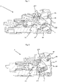
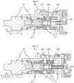
- the device of the invention essentially consists of a tube (1) passing through a volumetric pump, not shown, and which can be closed or opened by a clamp (2).
- the pump and the clamp (2) are placed in a box (3) which can be closed by a door (4).
- a so-called slide-clamp clamp consisting of two parts: a first fixed part (21) and a mobile part (22).
- the tube (1) passes through a substantially cylindrical opening (211) which has the particular function of holding it in place radially.
- This fixed part is integral with the casing (3) and does not move.
- the movable part (22) on the contrary can pivot around a pivot (221) which can be housed for example in the fixed part (21) of the clamp (2).
- This movable part (22) is provided with a slot (222) opening onto a wider part (223). The width of the slot (222) is chosen so that the tube (1) is flattened when it is engaged in it, thus finding itself obstructed.
- the opening (223) is wide enough for the tube (1) to be almost free of any constraint when it is inside so that it regains substantially its normal cylindrical shape leaving the passage to the pumped liquid.
- the tube is held in a slightly pinched shape which facilitates its entry into the slot (222).
- the opening (223) is however wide enough not to disturb the flow of the liquid.
- a transition section (224) moves the tube from the stress free position in the opening (223) to the flattened position in the slot (222).
- This movable part (22) of the gripper (2) can therefore pivot from an open position in which its opening (223) is substantially aligned with the opening (211) of the fixed part, position in which the tube (1) is open, to a closed position in which the opening (211) of the fixed part is aligned with the slot (222) of the mobile, position in which the flattened tube is closed.
- FIG 1 for example shows the closed position while the figure 3 shows the open position.
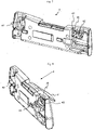
- the clamp (2) is closed by closing means fixed to the door (4).
- the door (4) is provided with a handle (41) to be pivoted to allow the opening or closing of the door (4).
- the handle (41) By pivoting the handle (41), the pivoting of the hooks (42) is caused.
- the hooks (42) hook corresponding projections of the housing (3) not shown here, preventing the door (4) from opening involuntarily.
- the handle (41) is in the pivoted position, the hooks (42) come off the projections allowing the opening of the door (4).
- the handle is mounted on a shaft (43) on which the hooks (42) are also mounted.
- the shaft (43) also carries a cam (44).
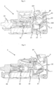
- This cam (44) can therefore also pivot between a pivoted position where it causes when the door (4) is closed the pivoting in the closed position of the movable part (22) of the gripper (2), and a folded position in which it no longer blocks the movable part (22) in the closed position.
- the pivoted position of the cam (44) is visible on the figure 1 , 4 , 7 and 8 , while the folded position is visible on the figure 2 And 3 .
- the cam (44) therefore plays the role of closing means both to close the clamp when the closing of the door is caused and to close the clamp when the opening of the door is caused.
- the axis (43) and the handle (41) constitute the means for causing the opening or closing of the door (4).
- the opening of the clamp (2) is provided by a movable finger (31) placed in the housing (3) and actuated by a motor (33).
- This finger (31) by moving in translation comes to press on the face of the movable part (22) of the gripper (2) opposite to that against which the cam (44) presses. This causes the movable part (22) to pivot from its closed position to its open position.
- This mobile finger (31) associated with the motor (33) constitutes the means for causing the opening of the gripper (2) after the door has been closed.
- the length of the slot (222) is such that the movable part (22) cannot return without outside help to the open position.
- the device is therefore with the door (4) closed and the tube (1) occluded. It is now possible, for example, to perform a pump integrity test without liquid being administered to the patient. If the test result is favorable, the finger (31) is actuated causing the pivoting in the open position of the movable part (22) of the gripper (2). The handle (4) being folded down, the cam (44) does not hinder this pivot movement. We find our in the position presented in picture 3 . Once the pivoting movement is completed, the finger (31) returns to its initial position which does not hinder the reverse pivoting movement caused by the cam (44).
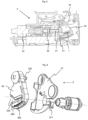
- the mode of operation of the mechanical fuse (32) is explained in more detail in figures 9 and 10 .
- the fuse (32) is provided with hooks (321) which are held in their working position visible to the figure 9 by a spring (323) which tends to push them radially outwards. These hooks (321) normally penetrate into notches (311) made in the finger (31).
- the motor (33) causes a retraction movement to the right, it drives the fuse (32) and with it the hooks (321).
- the motor (33) causes a translational movement to the right, it drives the fuse (32) and with it the hooks (321) which abut against the other end of the notches (311) of the finger (31). by dragging it into this general outward movement to the right. This is shown by the figure 3 And 9 .
- the cam (44) blocks the movement of the pivoting part (22) of the gripper (2), as in the case of the figure 5 , the hooks (321) then yield and pivot towards the center of the fuse (32) against the effect of the spring (323) thanks to bevels (324) located at their vertices on the face opposite the stops (322).
- the fuse is in the position shown in the figure 5 And 10 .
- the opening means, constituted by the finger (31), are thus deactivated and they can no longer cause the opening of the gripper (2).
- the fuse can automatically reset as soon as the motor (33) returns to its retracted position presented for example at the figure 1 .
- the spring (323) pushes the hooks (321) into the notches (311) of the finger (31) as soon as the fuse has moved back sufficiently.
- the exemplary embodiment shown here uses a clamp in which the tube is clamped in a pivotable slot. It goes without saying that the slot can also have a translation movement rather than a pivot movement. Similarly, it is just as well possible to use a snail clamp (also known as a pinch clamp) between two movable stops relative to each other, whether by translation or by pivoting.
- a snail clamp also known as a pinch clamp
- the movement of the finger (31) does not have to be a translation; it may very well be a pivoting movement for example.
- the electric motor can be replaced by a manual action or a mechanical device.
- the tube is not only always closed when the door is in the open position but also that it remains closed once the door is closed as long as a suitable device has not not caused the clamp to open.
- This entirely mechanical closing device is not subject to the vagaries of a possibly defective power supply.
Landscapes
- Health & Medical Sciences (AREA)
- Heart & Thoracic Surgery (AREA)
- Animal Behavior & Ethology (AREA)
- General Health & Medical Sciences (AREA)
- Biomedical Technology (AREA)
- Engineering & Computer Science (AREA)
- Hematology (AREA)
- Life Sciences & Earth Sciences (AREA)
- Veterinary Medicine (AREA)
- Anesthesiology (AREA)
- Public Health (AREA)
- Vascular Medicine (AREA)
- Pulmonology (AREA)
- Infusion, Injection, And Reservoir Apparatuses (AREA)
- Reciprocating Pumps (AREA)
- External Artificial Organs (AREA)
Claims (12)
- Verfahren zum Kontrollieren des Öffnens oder Schließens einer Klemme (2), die zum Verschließen eines flexiblen Schlauches (1) ausgebildet ist, der im Innern eines Gehäuses (3) angeordnet ist, das durch eine Tür (4) verschließbar ist, wobei die Klemme (2) in dem Gehäuse (3) angeordnet ist und mit dem Schlauch (1) zusammenwirkt, um ihn freizugeben oder zu verschließen, wobei die Klemme (2) von einer geöffneten in eine geschlossene Stellung übergeht, wenn das Schließen der Tür ausgelöst wird und nach dem Schließen der Tür in dieser geschlossenen Stellung verbleibt, solange Öffnungsmittel nicht das Öffnen der Klemme ausgelöst haben,dadurch gekennzeichnet,dass die Klemme (2) von der geöffneten Stellung in die geschlossene Stellung übergeht, wenn das Öffnen der Tür (4) ausgelöst wird, wobei Mittel (44) zum Schließen der Klemme (2), wenn das Öffnen der Tür (4) ausgelöst wird und Mittel (44) zum Schließen der Klemme (2), wenn das Schließen der Tür (4) ausgelöst wird, identisch sind,wobei die Mittel (44) zum Schließen der Klemme (2), wenn das Öffnen der Tür ausgelöst wird, und die Mittel (44) zum Schließen der Klemme (2), wenn das Schließen der Tür (4) ausgelöst wird, durch Mittel (41, 43) zum Auslösen des Öffnens oder des Schließens der Tür (4) betätigt werden.
- Verfahren gemäß Anspruch 1, dadurch gekennzeichnet, dass die Klemme (2) nach dem Schließen der Tür erst dann geöffnet wird, wenn ein vorherbestimmtes Ereignis stattgefunden hat, insbesondere nachdem ein Integritätstest erfolgreich durchgeführt wurde.
- Verfahren gemäß Anspruch 2, dadurch gekennzeichnet, dass das Wiederöffnen der Klemme (2) nicht erfolgt, wenn gleichzeitig das Öffnen der Tür (4) ausgelöst wird.
- Vorrichtung für die Kontrolle des Öffnens oder Schließens einer Klemme (2), die zum Verschließen eines flexiblen Schlauches (1), insbesondere in einer Volumenpumpe ausgebildet ist, die unter anderem umfasst:- ein Gehäuse (3), das durch eine Tür (4) verschließbar ist,- einen Schlauch (1), der in dem Gehäuse (3) angeordnet ist, und- eine Klemme (2), die in dem Gehäuse (3) angeordnet ist und mit dem Schlauch (1) zusammenwirkt, um ihn zu freizugeben oder zu verschließen,wobei Mittel (44) vorgesehen sind, um die Klemme (2) von einer geöffneten Stellung in eine geschlossene Stellung zu überführen, wenn das Schließen der Tür (4) ausgelöst wird und dass Mittel (31) vorgesehen sind, um das Öffnen der Klemme (2) auszulösen, nachdem die Tür (4) geschlossen wurde,dadurch gekennzeichnet,dass Mittel (44) vorgesehen sind, um die Klemme (2) von einer geöffneten Stellung in eine geschlossene Stellung zu überführen, wenn das Öffnen der Tür (4) ausgelöst wird, wobei die Mittel (44) zum Schließen der Klemme (2), wenn das Öffnen der Tür (4) ausgelöst wird, und die Mittel (44) zum Schließen der Klemme (2), wenn das Schließen der Tür (4) ausgelöst wird, identisch sind,wobei die Mittel (44) zum Schließen der Klemme (2), wenn das Öffnen der Tür ausgelöst wird und die Mittel (44) zum Schließen der Klemme (2), wenn das Schließen der Tür (4) ausgelöst wird, durch Mittel (41, 43) zum Auslösen des Öffnens oder des Schließens der Tür (4) betätigt werden.
- Vorrichtung gemäß Anspruch 4, dadurch gekennzeichnet, dass die Mittel zum Auslösen des Öffnens oder des Schließens der Tür einen Türgriff (41) umfassen, der von der Außenseite des Gehäuses (3) betätigbar ist.
- Vorrichtung gemäß Anspruch 4 oder 5, dadurch gekennzeichnet, dass die Mittel (44) zum Schließen der Klemme (2), wenn das Schließen der Tür (4) ausgelöst wird, und/oder die Mittel (44) zum Schließen der Klemme (2), wenn das Öffnen der Tür (4) ausgelöst wird, eine Nocke (44) umfassen, die mit den Mitteln (41, 43) zum Auslösen des Öffnens oder Schließens der Tür (4) zusammenwirken kann.
- Vorrichtung gemäß Anspruch 6, dadurch gekennzeichnet, dass die Nocke mit der Achse (43) des Türgriffs (41) fest verbunden ist.
- Vorrichtung gemäß einem der Ansprüche 4 bis 7, dadurch gekennzeichnet, dass die Klemme (2) aus einer Slide-Clamp besteht, die ein festes Teil (21) und ein bewegliches, vorzugsweise drehbewegliches, Teil (22) aufweist, wobei die Mittel zum Schließen der Klemme (2), wenn das Schließen der Tür ausgelöst wird oder die Mittel zum Schließen der Klemme (2), wenn das Öffnen der Tür ausgelöst wird so dimensioniert sind, das sie das Gleiten des beweglichen Teils (22) der Slide-Clamp relativ zum festen Teil (21) verursachen.
- Vorrichtung gemäß den Patentansprüchen 4 bis 8, dadurch gekennzeichnet, dass Steuermittel (33) vorgesehen sind, um die Mittel (31) zum Öffnen der Klemme (2) betätigen, wenn ein bestimmtes Ereignis stattgefunden hat.
- Vorrichtung gemäß Anspruch 9, dadurch gekennzeichnet, dass die Steuermittel ausgebildet sind, um die Mittel (31) zum Öffnen der Klemme (2) zu betätigen, nachdem ein Integritätstest des Systems durchgeführt wurde.
- Vorrichtung gemäß einem der Ansprüche 8 bis 10, dadurch gekennzeichnet, dass eine mechanische Sicherung (32) vorgesehen ist, um die Mittel (31 zum Öffnen der Klemme (2) zu inaktivieren, wenn das Öffnen der Tür in dem Moment erfolgt, in dem die Mittel zum Öffnen betätigt werden.
- Vorrichtung gemäß einem der Ansprüche 4 bis 11, dadurch gekennzeichnet, dass sie weiterhin eine volumetrische Pumpe, vorzugsweise eine peristaltische Pumpe umfasst, die mit dem Schlauch (1) verbunden ist, wobei die volumetrische Pumpe vorzugsweise strömungsaufwärts der Klemme (2) angeordnet ist.
Applications Claiming Priority (2)
| Application Number | Priority Date | Filing Date | Title |
|---|---|---|---|
| FR0609742A FR2908176B1 (fr) | 2006-11-08 | 2006-11-08 | Dispositif de controle de l'ouverture ou la fermeture d'une pince dans une pompe volumetrique |
| PCT/EP2007/061548 WO2008055793A1 (fr) | 2006-11-08 | 2007-10-26 | Dispositif de contrôle de l'ouverture ou la fermeture d'une pince dans une pompe volumétrique |
Publications (3)
| Publication Number | Publication Date |
|---|---|
| EP2089082A1 EP2089082A1 (de) | 2009-08-19 |
| EP2089082B1 EP2089082B1 (de) | 2015-05-20 |
| EP2089082B2 true EP2089082B2 (de) | 2023-02-22 |
Family
ID=37865786
Family Applications (1)
| Application Number | Title | Priority Date | Filing Date |
|---|---|---|---|
| EP07821908.6A Active EP2089082B2 (de) | 2006-11-08 | 2007-10-26 | Vorrichtung zur steuerung des öffnens und schliessens einer klammer bei einer verdrängerpumpe |
Country Status (6)
| Country | Link |
|---|---|
| US (1) | US8109898B2 (de) |
| EP (1) | EP2089082B2 (de) |
| JP (1) | JP5089702B2 (de) |
| CN (1) | CN101528286B (de) |
| FR (1) | FR2908176B1 (de) |
| WO (1) | WO2008055793A1 (de) |
Families Citing this family (28)
| Publication number | Priority date | Publication date | Assignee | Title |
|---|---|---|---|---|
| US9028691B2 (en) | 2007-02-27 | 2015-05-12 | Deka Products Limited Partnership | Blood circuit assembly for a hemodialysis system |
| US10201647B2 (en) | 2008-01-23 | 2019-02-12 | Deka Products Limited Partnership | Medical treatment system and methods using a plurality of fluid lines |
| US11833281B2 (en) | 2008-01-23 | 2023-12-05 | Deka Products Limited Partnership | Pump cassette and methods for use in medical treatment system using a plurality of fluid lines |
| WO2011053810A2 (en) | 2009-10-30 | 2011-05-05 | Deka Products Limited Partnership | Apparatus and method for detecting disconnection of an intravascular access device |
| US9677555B2 (en) | 2011-12-21 | 2017-06-13 | Deka Products Limited Partnership | System, method, and apparatus for infusing fluid |
| MX344664B (es) | 2011-05-24 | 2017-01-04 | Deka Products Lp | Sistemas y metodos de tratamiento de la sangre. |
| US9675756B2 (en) | 2011-12-21 | 2017-06-13 | Deka Products Limited Partnership | Apparatus for infusing fluid |
| US11295846B2 (en) | 2011-12-21 | 2022-04-05 | Deka Products Limited Partnership | System, method, and apparatus for infusing fluid |
| US10563681B2 (en) | 2011-12-21 | 2020-02-18 | Deka Products Limited Partnership | System, method, and apparatus for clamping |
| CN104245016B (zh) * | 2012-03-26 | 2016-10-05 | 泰尔茂株式会社 | 输液泵 |
| US9364655B2 (en) * | 2012-05-24 | 2016-06-14 | Deka Products Limited Partnership | Flexible tubing occlusion assembly |
| CN104507516B (zh) * | 2012-05-24 | 2018-02-16 | 德卡产品有限公司 | 用于输注流体的装置 |
| DE102013014217A1 (de) * | 2013-08-26 | 2015-02-26 | Thomas Magnete Gmbh | Schlauchklemme zum Halten und Verschließen eines Schlauchs |
| CA2959086C (en) | 2014-09-18 | 2023-11-14 | Deka Products Limited Partnership | Apparatus and method for infusing fluid through a tube by appropriately heating the tube |
| CN113181477B (zh) | 2015-06-04 | 2023-07-14 | 麦迪麦珀医疗工程有限公司 | 用于药物释放装置的筒插入 |
| CN107921205B (zh) * | 2015-08-25 | 2020-10-16 | 株式会社村田制作所 | 流体控制装置 |
| JP6644582B2 (ja) * | 2016-02-29 | 2020-02-12 | テルモ株式会社 | 医療用ポンプ |
| US10167861B2 (en) * | 2016-05-26 | 2019-01-01 | Namiki Precision Singapore Pte. Ltd. | Infusion pump |
| DE102017115862A1 (de) * | 2017-07-14 | 2019-01-17 | B. Braun Melsungen Ag | Vorrichtung zum Steuern des Öffnens und Schließens eines Schlauchs |
| DE102017116106A1 (de) * | 2017-07-18 | 2019-01-24 | B. Braun Melsungen Ag | Vorrichtung und Verfahren zum Öffnen und Schließen einer Infusionsschlauchklemme |
| JP6840891B2 (ja) * | 2017-08-10 | 2021-03-10 | ウェスト ファーマ サービシーズ イスラエル リミテッド | 注射器の自己テストおよびこれに応じた注射器ドアのロック解除機構 |
| JP7402799B2 (ja) | 2017-12-22 | 2023-12-21 | ウェスト ファーマ サービシーズ イスラエル リミテッド | サイズの異なるカートリッジを利用可能な注射器 |
| EP3787733A1 (de) | 2018-05-04 | 2021-03-10 | Fresenius Vial SAS | Infusionsvorrichtung mit einer klemmvorrichtung |
| WO2019243010A1 (en) | 2018-06-18 | 2019-12-26 | Fresenius Vial Sas | Infusion device comprising a clamping mechanism |
| KR20250117746A (ko) | 2018-08-16 | 2025-08-05 | 데카 프로덕츠 리미티드 파트너쉽 | 의료용 펌프 |
| USD917045S1 (en) | 2018-08-16 | 2021-04-20 | Deka Products Limited Partnership | Slide clamp |
| USD1004412S1 (en) | 2019-08-16 | 2023-11-14 | Deka Products Limited Partnership | Slide clamp assembly |
| US12044335B2 (en) | 2020-12-08 | 2024-07-23 | Sartorius Stedim North America Inc. | Pinch clamp for flexible conduits |
Citations (2)
| Publication number | Priority date | Publication date | Assignee | Title |
|---|---|---|---|---|
| EP0510881A2 (de) † | 1991-04-23 | 1992-10-28 | Minnesota Mining And Manufacturing Company | System zur Verhinderung eines freien Durchflusses in einer Infusionspumpe |
| WO2003041787A2 (de) † | 2001-11-15 | 2003-05-22 | Arcomed Ag | Sicherheitsvorrichtung für eine infusionspumpe |
Family Cites Families (6)
| Publication number | Priority date | Publication date | Assignee | Title |
|---|---|---|---|---|
| US4689043A (en) | 1986-03-19 | 1987-08-25 | Imed Corporation | IV tube activator |
| US5290239A (en) * | 1991-09-26 | 1994-03-01 | Baxter International, Inc. | Intravenous tube safety apparatus |
| US6261262B1 (en) | 1997-06-12 | 2001-07-17 | Abbott Laboratories | Pump with anti-free flow feature |
| FR2790041B1 (fr) * | 1999-02-23 | 2002-01-18 | Fresenius Vial | Procede de controle d'un dispositif de pompage comportant une pompe munie d'un tube souple et dispositif de mise en oeuvre du procede |
| DE19947973C2 (de) | 1999-10-05 | 2003-06-26 | Fresenius Ag | Einheit einer Infusionspumpe mit einem Infusionsschlauchset, sowie Schlauchklemme, Infusionspumpe und Infusionsschlauchset |
| US6629955B2 (en) * | 2001-05-04 | 2003-10-07 | Alaris Medical Systems, Inc. | Medical instrument flow stop interface |
-
2006
- 2006-11-08 FR FR0609742A patent/FR2908176B1/fr active Active
-
2007
- 2007-10-26 EP EP07821908.6A patent/EP2089082B2/de active Active
- 2007-10-26 JP JP2009535060A patent/JP5089702B2/ja not_active Expired - Fee Related
- 2007-10-26 US US12/513,785 patent/US8109898B2/en active Active
- 2007-10-26 CN CN2007800392896A patent/CN101528286B/zh not_active Expired - Fee Related
- 2007-10-26 WO PCT/EP2007/061548 patent/WO2008055793A1/fr not_active Ceased
Patent Citations (2)
| Publication number | Priority date | Publication date | Assignee | Title |
|---|---|---|---|---|
| EP0510881A2 (de) † | 1991-04-23 | 1992-10-28 | Minnesota Mining And Manufacturing Company | System zur Verhinderung eines freien Durchflusses in einer Infusionspumpe |
| WO2003041787A2 (de) † | 2001-11-15 | 2003-05-22 | Arcomed Ag | Sicherheitsvorrichtung für eine infusionspumpe |
Non-Patent Citations (1)
| Title |
|---|
| "Infusomat Space P", GEBRAUCHSANWEISUNG, January 2006 (2006-01-01) † |
Also Published As
| Publication number | Publication date |
|---|---|
| US8109898B2 (en) | 2012-02-07 |
| JP2010508876A (ja) | 2010-03-25 |
| US20100040481A1 (en) | 2010-02-18 |
| CN101528286A (zh) | 2009-09-09 |
| WO2008055793A1 (fr) | 2008-05-15 |
| FR2908176A1 (fr) | 2008-05-09 |
| EP2089082B1 (de) | 2015-05-20 |
| EP2089082A1 (de) | 2009-08-19 |
| FR2908176B1 (fr) | 2008-12-19 |
| CN101528286B (zh) | 2012-02-01 |
| JP5089702B2 (ja) | 2012-12-05 |
Similar Documents
| Publication | Publication Date | Title |
|---|---|---|
| EP2089082B2 (de) | Vorrichtung zur steuerung des öffnens und schliessens einer klammer bei einer verdrängerpumpe | |
| EP2766121B1 (de) | Hochsicherer steuermechanismus für eine vorrichtung zur dichten übertragung zwischen zwei geschlossenen räumen | |
| EP2183016B1 (de) | Klemme für einen schlauch, pumpe mit mittel zur öffnung einer solchen klemme und mit einer solchen klemme ausgestattetes infusionskit | |
| EP3581742B1 (de) | Flächenbündiger türgriff und verfahren zum betrieb davon | |
| EP2310141B1 (de) | Auftragvorrichtung eines fluids | |
| EP2319376B1 (de) | System zur Herstellung von Aufgussgetränken | |
| EP0190976B1 (de) | Schliesseinrichtung für Fahrzeugtüren | |
| FR2880809A1 (fr) | Dispositif de retenue pour bloquer la tete de piston d'une seringue sur le poussoir d'un pousse seringue | |
| EP1673530B1 (de) | Schubumkehrerverriegelung mit verriegelungsvorrichtung | |
| EP4166436B1 (de) | Scharnier mit einem entriegelungsorgan | |
| EP2717284B1 (de) | Bedienungsvorrichtung eines elektrischen Schutzschaltgeräts, und diese umfassendes elektrisches Schutzschaltgerät | |
| EP1734552B1 (de) | Betätigungseinrichtung eines elektrischen Schaltgeräts mit Drehsperre | |
| EP3922791A1 (de) | Elektrischer verriegelungsmechanismus für einen öffungsflügel mit mechanischer notfallfunktion | |
| EP2204828B1 (de) | Einrastmechanismus einer Hoch- und Mittelspannungs-Anlagensteuerung mit verbesserter Kompaktheit und verbesserten Kosten | |
| FR2877687A1 (fr) | Commande d'un systeme d'aeration a volets pivotants avec ouverture d'urgence | |
| EP3657522B1 (de) | Betätigungsmechanismus zum öffnen und schliessen einer stromunterbrechungsvorrichtung für einen elektrichen schalter | |
| EP1026345B1 (de) | Schloss mit einem System für elektrische Öffnungshilfe eines Kraftfahrzeugflügels | |
| FR2891569A1 (fr) | Dispositif pour manoeuvrer une porte coulissante, et vehicule automobile comportant une porte equipee d'un tel dispositif. | |
| EP1619073B1 (de) | Armmechanismus, insbesondere zur Handhabung, mit einer translatorischen Bewegung gefolgt von einer Schwenkbewegung | |
| FR2889961A1 (fr) | Dispositif pour maintenir une seringue dans une pompe | |
| FR2773836A1 (fr) | Fermeture de porte de vehicule automobile | |
| FR2737152A1 (fr) | Dispositif d'impression thermique evolutif | |
| BE402871A (de) | ||
| EP1338484A1 (de) | Aufprallschutzsystem für Fussgänger und damit ausgestattetes Fahrzeug | |
| BE532936A (de) |
Legal Events
| Date | Code | Title | Description |
|---|---|---|---|
| PUAI | Public reference made under article 153(3) epc to a published international application that has entered the european phase |
Free format text: ORIGINAL CODE: 0009012 |
|
| 17P | Request for examination filed |
Effective date: 20090313 |
|
| AK | Designated contracting states |
Kind code of ref document: A1 Designated state(s): AT BE BG CH CY CZ DE DK EE ES FI FR GB GR HU IE IS IT LI LT LU LV MC MT NL PL PT RO SE SI SK TR |
|
| DAX | Request for extension of the european patent (deleted) | ||
| 17Q | First examination report despatched |
Effective date: 20110728 |
|
| REG | Reference to a national code |
Ref country code: DE Ref legal event code: R079 Ref document number: 602007041520 Country of ref document: DE Free format text: PREVIOUS MAIN CLASS: A61M0005168000 Ipc: A61M0005142000 |
|
| RIC1 | Information provided on ipc code assigned before grant |
Ipc: A61M 39/28 20060101ALI20141030BHEP Ipc: A61M 5/142 20060101AFI20141030BHEP Ipc: A61M 5/168 20060101ALI20141030BHEP |
|
| GRAP | Despatch of communication of intention to grant a patent |
Free format text: ORIGINAL CODE: EPIDOSNIGR1 |
|
| INTG | Intention to grant announced |
Effective date: 20150113 |
|
| GRAS | Grant fee paid |
Free format text: ORIGINAL CODE: EPIDOSNIGR3 |
|
| GRAA | (expected) grant |
Free format text: ORIGINAL CODE: 0009210 |
|
| AK | Designated contracting states |
Kind code of ref document: B1 Designated state(s): AT BE BG CH CY CZ DE DK EE ES FI FR GB GR HU IE IS IT LI LT LU LV MC MT NL PL PT RO SE SI SK TR |
|
| REG | Reference to a national code |
Ref country code: GB Ref legal event code: FG4D Free format text: NOT ENGLISH |
|
| REG | Reference to a national code |
Ref country code: CH Ref legal event code: EP |
|
| REG | Reference to a national code |
Ref country code: AT Ref legal event code: REF Ref document number: 727415 Country of ref document: AT Kind code of ref document: T Effective date: 20150615 |
|
| REG | Reference to a national code |
Ref country code: IE Ref legal event code: FG4D Free format text: LANGUAGE OF EP DOCUMENT: FRENCH |
|
| REG | Reference to a national code |
Ref country code: DE Ref legal event code: R096 Ref document number: 602007041520 Country of ref document: DE Effective date: 20150702 |
|
| REG | Reference to a national code |
Ref country code: AT Ref legal event code: MK05 Ref document number: 727415 Country of ref document: AT Kind code of ref document: T Effective date: 20150520 |
|
| REG | Reference to a national code |
Ref country code: FR Ref legal event code: PLFP Year of fee payment: 9 |
|
| REG | Reference to a national code |
Ref country code: LT Ref legal event code: MG4D |
|
| REG | Reference to a national code |
Ref country code: NL Ref legal event code: MP Effective date: 20150520 |
|
| PG25 | Lapsed in a contracting state [announced via postgrant information from national office to epo] |
Ref country code: ES Free format text: LAPSE BECAUSE OF FAILURE TO SUBMIT A TRANSLATION OF THE DESCRIPTION OR TO PAY THE FEE WITHIN THE PRESCRIBED TIME-LIMIT Effective date: 20150520 Ref country code: PT Free format text: LAPSE BECAUSE OF FAILURE TO SUBMIT A TRANSLATION OF THE DESCRIPTION OR TO PAY THE FEE WITHIN THE PRESCRIBED TIME-LIMIT Effective date: 20150921 Ref country code: LT Free format text: LAPSE BECAUSE OF FAILURE TO SUBMIT A TRANSLATION OF THE DESCRIPTION OR TO PAY THE FEE WITHIN THE PRESCRIBED TIME-LIMIT Effective date: 20150520 Ref country code: FI Free format text: LAPSE BECAUSE OF FAILURE TO SUBMIT A TRANSLATION OF THE DESCRIPTION OR TO PAY THE FEE WITHIN THE PRESCRIBED TIME-LIMIT Effective date: 20150520 |
|
| PG25 | Lapsed in a contracting state [announced via postgrant information from national office to epo] |
Ref country code: IS Free format text: LAPSE BECAUSE OF FAILURE TO SUBMIT A TRANSLATION OF THE DESCRIPTION OR TO PAY THE FEE WITHIN THE PRESCRIBED TIME-LIMIT Effective date: 20150920 Ref country code: LV Free format text: LAPSE BECAUSE OF FAILURE TO SUBMIT A TRANSLATION OF THE DESCRIPTION OR TO PAY THE FEE WITHIN THE PRESCRIBED TIME-LIMIT Effective date: 20150520 Ref country code: AT Free format text: LAPSE BECAUSE OF FAILURE TO SUBMIT A TRANSLATION OF THE DESCRIPTION OR TO PAY THE FEE WITHIN THE PRESCRIBED TIME-LIMIT Effective date: 20150520 Ref country code: BG Free format text: LAPSE BECAUSE OF FAILURE TO SUBMIT A TRANSLATION OF THE DESCRIPTION OR TO PAY THE FEE WITHIN THE PRESCRIBED TIME-LIMIT Effective date: 20150820 Ref country code: GR Free format text: LAPSE BECAUSE OF FAILURE TO SUBMIT A TRANSLATION OF THE DESCRIPTION OR TO PAY THE FEE WITHIN THE PRESCRIBED TIME-LIMIT Effective date: 20150821 |
|
| PG25 | Lapsed in a contracting state [announced via postgrant information from national office to epo] |
Ref country code: EE Free format text: LAPSE BECAUSE OF FAILURE TO SUBMIT A TRANSLATION OF THE DESCRIPTION OR TO PAY THE FEE WITHIN THE PRESCRIBED TIME-LIMIT Effective date: 20150520 Ref country code: DK Free format text: LAPSE BECAUSE OF FAILURE TO SUBMIT A TRANSLATION OF THE DESCRIPTION OR TO PAY THE FEE WITHIN THE PRESCRIBED TIME-LIMIT Effective date: 20150520 |
|
| REG | Reference to a national code |
Ref country code: DE Ref legal event code: R026 Ref document number: 602007041520 Country of ref document: DE |
|
| PLBI | Opposition filed |
Free format text: ORIGINAL CODE: 0009260 |
|
| PG25 | Lapsed in a contracting state [announced via postgrant information from national office to epo] |
Ref country code: CZ Free format text: LAPSE BECAUSE OF FAILURE TO SUBMIT A TRANSLATION OF THE DESCRIPTION OR TO PAY THE FEE WITHIN THE PRESCRIBED TIME-LIMIT Effective date: 20150520 Ref country code: RO Free format text: LAPSE BECAUSE OF NON-PAYMENT OF DUE FEES Effective date: 20150520 Ref country code: SK Free format text: LAPSE BECAUSE OF FAILURE TO SUBMIT A TRANSLATION OF THE DESCRIPTION OR TO PAY THE FEE WITHIN THE PRESCRIBED TIME-LIMIT Effective date: 20150520 Ref country code: PL Free format text: LAPSE BECAUSE OF FAILURE TO SUBMIT A TRANSLATION OF THE DESCRIPTION OR TO PAY THE FEE WITHIN THE PRESCRIBED TIME-LIMIT Effective date: 20150520 |
|
| 26 | Opposition filed |
Opponent name: B. BRAUN MELSUNGEN AG Effective date: 20160212 |
|
| PLAX | Notice of opposition and request to file observation + time limit sent |
Free format text: ORIGINAL CODE: EPIDOSNOBS2 |
|
| PG25 | Lapsed in a contracting state [announced via postgrant information from national office to epo] |
Ref country code: IT Free format text: LAPSE BECAUSE OF FAILURE TO SUBMIT A TRANSLATION OF THE DESCRIPTION OR TO PAY THE FEE WITHIN THE PRESCRIBED TIME-LIMIT Effective date: 20150520 |
|
| PG25 | Lapsed in a contracting state [announced via postgrant information from national office to epo] |
Ref country code: SI Free format text: LAPSE BECAUSE OF FAILURE TO SUBMIT A TRANSLATION OF THE DESCRIPTION OR TO PAY THE FEE WITHIN THE PRESCRIBED TIME-LIMIT Effective date: 20150520 Ref country code: LU Free format text: LAPSE BECAUSE OF FAILURE TO SUBMIT A TRANSLATION OF THE DESCRIPTION OR TO PAY THE FEE WITHIN THE PRESCRIBED TIME-LIMIT Effective date: 20151026 |
|
| REG | Reference to a national code |
Ref country code: CH Ref legal event code: PL |
|
| PG25 | Lapsed in a contracting state [announced via postgrant information from national office to epo] |
Ref country code: MC Free format text: LAPSE BECAUSE OF FAILURE TO SUBMIT A TRANSLATION OF THE DESCRIPTION OR TO PAY THE FEE WITHIN THE PRESCRIBED TIME-LIMIT Effective date: 20150520 |
|
| PLAB | Opposition data, opponent's data or that of the opponent's representative modified |
Free format text: ORIGINAL CODE: 0009299OPPO |
|
| PLAF | Information modified related to communication of a notice of opposition and request to file observations + time limit |
Free format text: ORIGINAL CODE: EPIDOSCOBS2 |
|
| REG | Reference to a national code |
Ref country code: IE Ref legal event code: MM4A |
|
| PG25 | Lapsed in a contracting state [announced via postgrant information from national office to epo] |
Ref country code: LI Free format text: LAPSE BECAUSE OF NON-PAYMENT OF DUE FEES Effective date: 20151031 Ref country code: CH Free format text: LAPSE BECAUSE OF NON-PAYMENT OF DUE FEES Effective date: 20151031 |
|
| R26 | Opposition filed (corrected) |
Opponent name: B. BRAUN MELSUNGEN AG Effective date: 20160212 |
|
| PLBB | Reply of patent proprietor to notice(s) of opposition received |
Free format text: ORIGINAL CODE: EPIDOSNOBS3 |
|
| REG | Reference to a national code |
Ref country code: FR Ref legal event code: PLFP Year of fee payment: 10 |
|
| PG25 | Lapsed in a contracting state [announced via postgrant information from national office to epo] |
Ref country code: IE Free format text: LAPSE BECAUSE OF NON-PAYMENT OF DUE FEES Effective date: 20151026 |
|
| PG25 | Lapsed in a contracting state [announced via postgrant information from national office to epo] |
Ref country code: HU Free format text: LAPSE BECAUSE OF FAILURE TO SUBMIT A TRANSLATION OF THE DESCRIPTION OR TO PAY THE FEE WITHIN THE PRESCRIBED TIME-LIMIT; INVALID AB INITIO Effective date: 20071026 |
|
| PG25 | Lapsed in a contracting state [announced via postgrant information from national office to epo] |
Ref country code: CY Free format text: LAPSE BECAUSE OF FAILURE TO SUBMIT A TRANSLATION OF THE DESCRIPTION OR TO PAY THE FEE WITHIN THE PRESCRIBED TIME-LIMIT Effective date: 20150520 Ref country code: NL Free format text: LAPSE BECAUSE OF FAILURE TO SUBMIT A TRANSLATION OF THE DESCRIPTION OR TO PAY THE FEE WITHIN THE PRESCRIBED TIME-LIMIT Effective date: 20150520 Ref country code: SE Free format text: LAPSE BECAUSE OF FAILURE TO SUBMIT A TRANSLATION OF THE DESCRIPTION OR TO PAY THE FEE WITHIN THE PRESCRIBED TIME-LIMIT Effective date: 20150520 |
|
| PG25 | Lapsed in a contracting state [announced via postgrant information from national office to epo] |
Ref country code: BE Free format text: LAPSE BECAUSE OF NON-PAYMENT OF DUE FEES Effective date: 20151031 |
|
| PG25 | Lapsed in a contracting state [announced via postgrant information from national office to epo] |
Ref country code: TR Free format text: LAPSE BECAUSE OF FAILURE TO SUBMIT A TRANSLATION OF THE DESCRIPTION OR TO PAY THE FEE WITHIN THE PRESCRIBED TIME-LIMIT Effective date: 20150520 Ref country code: MT Free format text: LAPSE BECAUSE OF FAILURE TO SUBMIT A TRANSLATION OF THE DESCRIPTION OR TO PAY THE FEE WITHIN THE PRESCRIBED TIME-LIMIT Effective date: 20150520 |
|
| REG | Reference to a national code |
Ref country code: FR Ref legal event code: PLFP Year of fee payment: 11 |
|
| APAH | Appeal reference modified |
Free format text: ORIGINAL CODE: EPIDOSCREFNO |
|
| APBM | Appeal reference recorded |
Free format text: ORIGINAL CODE: EPIDOSNREFNO |
|
| APBP | Date of receipt of notice of appeal recorded |
Free format text: ORIGINAL CODE: EPIDOSNNOA2O |
|
| APBQ | Date of receipt of statement of grounds of appeal recorded |
Free format text: ORIGINAL CODE: EPIDOSNNOA3O |
|
| REG | Reference to a national code |
Ref country code: FR Ref legal event code: PLFP Year of fee payment: 12 |
|
| APBU | Appeal procedure closed |
Free format text: ORIGINAL CODE: EPIDOSNNOA9O |
|
| PUAH | Patent maintained in amended form |
Free format text: ORIGINAL CODE: 0009272 |
|
| STAA | Information on the status of an ep patent application or granted ep patent |
Free format text: STATUS: PATENT MAINTAINED AS AMENDED |
|
| 27A | Patent maintained in amended form |
Effective date: 20230222 |
|
| AK | Designated contracting states |
Kind code of ref document: B2 Designated state(s): AT BE BG CH CY CZ DE DK EE ES FI FR GB GR HU IE IS IT LI LT LU LV MC MT NL PL PT RO SE SI SK TR |
|
| REG | Reference to a national code |
Ref country code: DE Ref legal event code: R102 Ref document number: 602007041520 Country of ref document: DE |
|
| P01 | Opt-out of the competence of the unified patent court (upc) registered |
Effective date: 20230528 |
|
| PGFP | Annual fee paid to national office [announced via postgrant information from national office to epo] |
Ref country code: DE Payment date: 20251029 Year of fee payment: 19 |
|
| PGFP | Annual fee paid to national office [announced via postgrant information from national office to epo] |
Ref country code: GB Payment date: 20251027 Year of fee payment: 19 |
|
| PGFP | Annual fee paid to national office [announced via postgrant information from national office to epo] |
Ref country code: FR Payment date: 20251027 Year of fee payment: 19 |