EP0897435B1 - Procede de construction d'une digue inclinee - Google Patents
Procede de construction d'une digue inclinee Download PDFInfo
- Publication number
- EP0897435B1 EP0897435B1 EP97921634A EP97921634A EP0897435B1 EP 0897435 B1 EP0897435 B1 EP 0897435B1 EP 97921634 A EP97921634 A EP 97921634A EP 97921634 A EP97921634 A EP 97921634A EP 0897435 B1 EP0897435 B1 EP 0897435B1
- Authority
- EP
- European Patent Office
- Prior art keywords
- embankment
- front grid
- anchor
- grid
- anchor element
- Prior art date
- Legal status (The legal status is an assumption and is not a legal conclusion. Google has not performed a legal analysis and makes no representation as to the accuracy of the status listed.)
- Expired - Lifetime
Links
- 238000000034 method Methods 0.000 title claims abstract description 39
- 238000010276 construction Methods 0.000 claims abstract description 20
- 230000015572 biosynthetic process Effects 0.000 claims abstract description 8
- 239000000463 material Substances 0.000 claims description 16
- 230000007797 corrosion Effects 0.000 claims description 11
- 238000005260 corrosion Methods 0.000 claims description 11
- 239000004746 geotextile Substances 0.000 claims description 8
- -1 gravel Substances 0.000 claims description 5
- 239000004576 sand Substances 0.000 claims description 5
- 230000002787 reinforcement Effects 0.000 description 22
- 239000011248 coating agent Substances 0.000 description 6
- 238000000576 coating method Methods 0.000 description 6
- 238000004873 anchoring Methods 0.000 description 5
- 230000003628 erosive effect Effects 0.000 description 3
- 239000000203 mixture Substances 0.000 description 3
- XEEYBQQBJWHFJM-UHFFFAOYSA-N Iron Chemical compound [Fe] XEEYBQQBJWHFJM-UHFFFAOYSA-N 0.000 description 2
- 229910000831 Steel Inorganic materials 0.000 description 2
- 238000009434 installation Methods 0.000 description 2
- 239000002689 soil Substances 0.000 description 2
- 239000010959 steel Substances 0.000 description 2
- 239000004575 stone Substances 0.000 description 2
- 230000006978 adaptation Effects 0.000 description 1
- 239000004411 aluminium Substances 0.000 description 1
- XAGFODPZIPBFFR-UHFFFAOYSA-N aluminium Chemical compound [Al] XAGFODPZIPBFFR-UHFFFAOYSA-N 0.000 description 1
- 229910052782 aluminium Inorganic materials 0.000 description 1
- 239000010426 asphalt Substances 0.000 description 1
- 230000000694 effects Effects 0.000 description 1
- 238000009415 formwork Methods 0.000 description 1
- 229910052742 iron Inorganic materials 0.000 description 1
- 238000004519 manufacturing process Methods 0.000 description 1
- 238000002844 melting Methods 0.000 description 1
- 230000008018 melting Effects 0.000 description 1
- 239000011490 mineral wool Substances 0.000 description 1
- 238000001556 precipitation Methods 0.000 description 1
- 238000003825 pressing Methods 0.000 description 1
- 239000012779 reinforcing material Substances 0.000 description 1
- 238000009331 sowing Methods 0.000 description 1
- XLYOFNOQVPJJNP-UHFFFAOYSA-N water Substances O XLYOFNOQVPJJNP-UHFFFAOYSA-N 0.000 description 1
- 238000009941 weaving Methods 0.000 description 1
Images


Classifications
-
- E—FIXED CONSTRUCTIONS
- E02—HYDRAULIC ENGINEERING; FOUNDATIONS; SOIL SHIFTING
- E02D—FOUNDATIONS; EXCAVATIONS; EMBANKMENTS; UNDERGROUND OR UNDERWATER STRUCTURES
- E02D29/00—Independent underground or underwater structures; Retaining walls
- E02D29/02—Retaining or protecting walls
- E02D29/0225—Retaining or protecting walls comprising retention means in the backfill
- E02D29/0241—Retaining or protecting walls comprising retention means in the backfill the retention means being reinforced earth elements
-
- E—FIXED CONSTRUCTIONS
- E02—HYDRAULIC ENGINEERING; FOUNDATIONS; SOIL SHIFTING
- E02D—FOUNDATIONS; EXCAVATIONS; EMBANKMENTS; UNDERGROUND OR UNDERWATER STRUCTURES
- E02D17/00—Excavations; Bordering of excavations; Making embankments
- E02D17/18—Making embankments, e.g. dikes, dams
-
- E—FIXED CONSTRUCTIONS
- E02—HYDRAULIC ENGINEERING; FOUNDATIONS; SOIL SHIFTING
- E02D—FOUNDATIONS; EXCAVATIONS; EMBANKMENTS; UNDERGROUND OR UNDERWATER STRUCTURES
- E02D29/00—Independent underground or underwater structures; Retaining walls
- E02D29/02—Retaining or protecting walls
- E02D29/0225—Retaining or protecting walls comprising retention means in the backfill
Definitions
- This invention concerns a method for constructing a steep embankment or slope.
- various techniques are known for building steep slopes.
- the known techniques stem from the wish to achieve stable slopes since, in many cases, for construction purposes or traffic related reasons it is necessary to execute a given embankment so steep that the embankment cannot be constructed solely with earth or gravel materials and would not in itself be stable enough to resist erosion for a longer period of time. Particularly it cannot resist erosion due to precipitation, including rain showers, the effects of melting water etc.
- Such an embankment must furthermore in certain cases fulfil specific requirements or wishes with regard to appearance, including vegetation, stone kerbing, wooden or facade coating.
- An object of the present invention is to achieve a technique which eliminates the aforesaid drawback in the prior art, and particularly enables a more flexible adaptation and construction of an embankment on site and at the same time enables the construction of an embankment using a universal set of elements which may be produced with universal dimensions and combined on site according to a given required embodiment, i.e. corresponding to the embankment to be constructed.
- the basis of this invention is the recognition that by using a planar grid constituting a planar front grid in the completed embankment, an anchor element which consist of an anchorage grid, an anchor peg or an anchor block as well as one or more anchorage braces or struts, a reinforcement may be constructed in an embankment, it being possible to construct said reinforcement on site and adapt it to the given specifications and requirements, including ad hoc adjustment.
- a reinforcement may be constructed in an embankment, it being possible to construct said reinforcement on site and adapt it to the given specifications and requirements, including ad hoc adjustment.
- Erecting of the front grid according to the method of the invention may take place in any suitable way, including fixing of the front grid by means of anchoring pegs driven down at the bottom edge of the front grid once it has been raised to the desired inclination in relation to horizontal and possibly temporarily supported and fixed by means of temporary anchor struts or the like.
- a stable securing of the front grid is carried out by digging a trench prior to or during the erection of the planar front grid and erecting and securing the planar front grid in said trench using sand, gravel, concrete or a mixture thereof.
- the method according to this invention preferably further comprises a step wherein one or more layers of geo-net and one or more layers of geo-textiles which may be mutually interconnected or placed overlapping one another under or above the anchor element as well as preferably behind the front grid.
- the front grid may constitute a component left in place after construction of the ) embankment and, depending on the specific use, it may be made from corrosion-resistant material or alternatively from non corrosion-resistant material. If the front grid is to remain intact as a reinforcement element in the embankment even after a long span of years, the front grid must naturally be made from corrosion-resistant material. In case of subsequent planting and thereby so to say natural reinforcement of the embankment built according to the method of the invention the front grid may be made from non corrosion-resistant material, the front grid corroding away after a period of time.
- the method may, according to an alternative embodiment, further comprise the final step of removing the front grid after construction of the finished embankment, including any planting on the completed embankment.
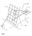
- the method of building steep embankments in earth comprises the digging of a trench 1 having a depth and a width of approximately 30 cm for receiving and securing a front grid 2 at an angle corresponding to that of the completed embankment.
- the front grid 2 is a per se conventional reinforcement grid made of iron, steel, aluminium or other suitable material or a combination thereof.
- the front grid may be corrosion resistant in order to impede the decay of the front grid over time or, as an alternative, it may constitute a non corrosion resistant breakable front grid which deliberately decays within a shorter or longer period of time after the embankment has been established.
- the front grid has a mesh size varying according to the given use between 5 and 50 cm, typically 10-20 cm, like 15 cm.
- a temporary bracing 3 Sand, gravel, concrete or a mixture thereof is poured into the trench 1 for securing the front grid 2, and the inclination thereof is stabilized by anchoring on the side where the earth reinforcement is to made by means of two anchor braces or struts 4a and 4b.
- the anchor braces or struts 4a and 4b are fixed in the ground by means of a fixing peg or bracket 6 and at the other and they are fixed at the front grid 2 on the same sloping grid line so that the anchor brace or strut 4b is lying on the ground, that the brace or strut 4a forms an angle ⁇ less than 90° with the inclined plane of the front grid 2 and that the point of fixture at the front grid is situated at a height less that 0,5 m.
- the anchor brace or strut 4b may be secured closer to the front grid but preferably on the same ground projection line of the anchor brace or strut 4a and at an angle ⁇ with the front-grid normally smaller than the angle ⁇ .
- the anchor braces or struts are also secured by means of the fixing peg to an anchor element 5 in such a manner that the combined translatory and rotary movement of the anchor braces or struts 4a and 4b is prevented by the resistance of the anchor element 5.
- the anchor element 5 (which may be an anchor grid as in fig. 1, an anchor peg as in fig. 2 or an anchor block as in fig. 3) is placed at a certain distance in the longitudinal direction from the grid, typically a distance of 1-5 m, like 1-3 m, preferably about 1 m. Even though the anchor braces or struts 4a and 4b in fig. 1 are shown secured by means of the fixing peg 6, the anchor braces or struts 4a and 4b may, as an alternative, be secured directly to the anchor element 5.
- the position of the anchor braces or struts 4a and 4b with relation to the anchor grid 5 and the front grid 2 may be changed according to the given use and that according to the given use, a varying number of anchor braces or struts may be used in connection with a front grid depending on the given circumstances, including especially the angle or inclination of the front grid in relation to horizontal and the given soil conditions.
- Fig. 2 is a schematic perspective view of a first alternative embodiment of a method according to the present invention similar to the preferred embodiment shown in fig. 1, but with the front grid 2 anchored by means of anchor pegs 5.
- Fig. 3 is a schematic perspective view of a second alternative embodiment of a method according to the present invention similar to the first alternative embodiment shown in fig. 2, but with the front grid 2 anchored by means of anchor blocks 5.
- Fig. 4 shows a schematic cross-section view of a steep embankment built by repetition of the method described above with reference to fig. 1.
- steps are carried out:
- the steps a-h are repeated until the height of the structure corresponds to the desired height of the embankment and it may be covered by the material chosen to serve the desired purpose, e.g asphalt -for road construction- or trees and/or bushes -to prevent landslides.
- reinforcement material 7 may instead be used steel net, the mesh size and dimensions of which may vary according to the design.
- the plant mat 8 may be a biodegradable coir mat or a geo-textile which is positioned immediately behind the facade of the wall and has the purpose of holding back top soil and which is built into the front of the embankment and of ensuring that the subsequent sowing is bound to the embankment.
- Special mats of mineral wool may also optionally be used.
- Fig. 5 is a schematic cross-section view of a steep embankment having a displaced front and being built in accordance with the method according to the present invention.
- the construction of the steep embankment is initiated in the same way as the construction of the embankment shown in fig. 4, but each time the construction of an individual section of the displaced front is started, a new front grid 2' (possibly 2", 2"' etc. not shown in the figure) is positioned at a distance from and rearwardly displaced with respect to the front grid 2.
- the layer of reinforcing material 7 is countersunk for a distance behind the front grid 2 and dug down at the position where the second front grid 2' is to be installed.
- Fig. 6 is a schematic cross-section view of a steep embankment built according to the method of the present invention and having a set back reinforcement net 7 and stonework 9.
- the principle of construction is like the principle described in connection with fig. 5; but the reinforcement net 7, however, is placed at a distance from the front grid 2 to provide space between the front grid 2 and the reinforcement net 7 for filling up with stones simultaneously with the other side of the reinforcement net 7 is filled with earth.
- Fig. 7 is a schematic cross-section view built up in accordance with the method of the present invention and having an outer coating 10 which is secured by means of brackets 11, which again are anchored in the embankment by means of a number of anchor braces or struts 12.
- the embankment is otherwise constructed equivalently to the embankment described above with reference to fig. 5, however, without a displaced front.
- an embankment is established in a simple way by means of universally applicable elements, a front grid, an anchor element, a number of anchor braces or struts and one or more layers of geo-net or one or more layers of geo-textiles, said embankment having any inclination and being designed with any desired outward appearance, including planting, coating etc.
- the technique according to the present invention does not set out any specific requirements as to the design of especially configured components such as especially designed support grids, and the erection of the reinforcement system according to the present invention may be carried out according to the given conditions on a plane or slightly sloping ground and may furthermore be directly integrated with already existing facilities.
- the front grid may be removed after construction of the embankment or alternatively be left within the embankment for subsequent corrosion or alternatively it may serve as formwork during the construction of a coating.
- the front grid may furthermore serve as protection against malicious damage, vandalism, erosion etc. for a long span of years.
- the stability of the embankment is secured by the remaining reinforcement elements, including the anchor element, the geo-nets or the geo-textiles.
- a facade coating may be designed in the form of stonework, whereupon the reinforcement material should not be visible and this is facilitated by erecting the reinforcement material at a distance behind the front of the completed embankment, whereby the front grid serves to determine the overall stability of the embankment and consequently should be constructed of corrosion-resistant material.
- the technique according to the present invention may furthermore be used for construction of dams and coast protection installations or other similar safety installations.
Landscapes
- Engineering & Computer Science (AREA)
- Mining & Mineral Resources (AREA)
- Life Sciences & Earth Sciences (AREA)
- General Life Sciences & Earth Sciences (AREA)
- Paleontology (AREA)
- Civil Engineering (AREA)
- General Engineering & Computer Science (AREA)
- Structural Engineering (AREA)
- Environmental & Geological Engineering (AREA)
- Pit Excavations, Shoring, Fill Or Stabilisation Of Slopes (AREA)
- Investigation Of Foundation Soil And Reinforcement Of Foundation Soil By Compacting Or Drainage (AREA)
- Nitrogen And Oxygen Or Sulfur-Condensed Heterocyclic Ring Systems (AREA)
- Paper (AREA)
- Indole Compounds (AREA)
- Photoreceptors In Electrophotography (AREA)
- Piles And Underground Anchors (AREA)
- Building Environments (AREA)
- Buildings Adapted To Withstand Abnormal External Influences (AREA)
- Hydrogenated Pyridines (AREA)
- Tents Or Canopies (AREA)
- Crystals, And After-Treatments Of Crystals (AREA)
- Silver Salt Photography Or Processing Solution Therefor (AREA)
- Electrical Discharge Machining, Electrochemical Machining, And Combined Machining (AREA)
Claims (4)
- Méthode pour la construction d'une pente raide ou d'un escarpement, la méthode comprenant les étapes suivantes:(a) creuser une excavation dans laquelle un grillage frontal plan est placé et fixé avec du sable, du gravier, du béton ou une combination de cela, le grillage frontal plan ayant une inclinaison correspondante à la pente à achever et étant placé immédiatement adjacent à la face de la pente à achever;(b) placer un élément d'ancrage à un point dans la formation de terre derrière la pente à achever, l'élément d'ancrage étant constitué par un grillage d'ancrage, un piquet d'ancrage, un bloc d'ancrage ou analogues ou une combination de cela;(c) établir un ancrage ou plusieurs ancrages fixés entre le grillage frontal plan et l'élément d'ancrage par moyens d'un ou plusieurs étrésillons ou étais d'ancrage qui fixent le grillage frontal par rapport à l'élément d'ancrage; et(d) remplir la zone derrière le grillage frontal et couvrir l'élément d'ancrage pour fournir la formation de terre dans la pente achevée.
- Méthode selon la revendication 1, CHARACTÉRISÉE en ce que la méthode comprend en outre une étape d'insertion d'une ou plusieurs couches de géonet ou d'une ou plusieurs couches de géotextiles pouvant être réciproquement liées ou placées en recouvrement, au-dessous ou au-dessus de l'élément d'ancrage et de préférence également derrière le grillage frontal.
- Méthode selon la revendication 1 ou 2, CHARACTÉRISÉE en ce que le grillage frontal est constitué d'un matériau résistant aux corrosions ou alternativement, d'un matériau non résistant aux corrosions.
- Méthode selon l'une quelconque des revendications 1 à 3, CHARACTÉRISÉE en ce que la méthode comprend en outre l'étape finale par laquelle le grillage frontal est retiré après la construction de la pente achevée et éventuellement la mise en place d'une plantation sur la pente achevée.
Priority Applications (1)
| Application Number | Priority Date | Filing Date | Title |
|---|---|---|---|
| EP02013855A EP1256660A1 (fr) | 1996-05-10 | 1997-05-07 | Méthode de stabilisation des talus |
Applications Claiming Priority (3)
| Application Number | Priority Date | Filing Date | Title |
|---|---|---|---|
| DK56396 | 1996-05-10 | ||
| DK056396A DK56396A (da) | 1996-05-10 | 1996-05-10 | Fremgangsmåde til opbygning af en stejl skråning, system til brug ved opbygning af den stejle skråning og en sådan skråning |
| PCT/DK1997/000209 WO1997043489A1 (fr) | 1996-05-10 | 1997-05-07 | Procede de construction d'une digue inclinee, systeme servant a la formation de ladite digue, et digue ainsi construite |
Related Child Applications (1)
| Application Number | Title | Priority Date | Filing Date |
|---|---|---|---|
| EP02013855A Division EP1256660A1 (fr) | 1996-05-10 | 1997-05-07 | Méthode de stabilisation des talus |
Publications (2)
| Publication Number | Publication Date |
|---|---|
| EP0897435A1 EP0897435A1 (fr) | 1999-02-24 |
| EP0897435B1 true EP0897435B1 (fr) | 2002-12-04 |
Family
ID=8094960
Family Applications (2)
| Application Number | Title | Priority Date | Filing Date |
|---|---|---|---|
| EP02013855A Withdrawn EP1256660A1 (fr) | 1996-05-10 | 1997-05-07 | Méthode de stabilisation des talus |
| EP97921634A Expired - Lifetime EP0897435B1 (fr) | 1996-05-10 | 1997-05-07 | Procede de construction d'une digue inclinee |
Family Applications Before (1)
| Application Number | Title | Priority Date | Filing Date |
|---|---|---|---|
| EP02013855A Withdrawn EP1256660A1 (fr) | 1996-05-10 | 1997-05-07 | Méthode de stabilisation des talus |
Country Status (8)
| Country | Link |
|---|---|
| EP (2) | EP1256660A1 (fr) |
| AT (1) | ATE229110T1 (fr) |
| AU (1) | AU2763697A (fr) |
| DE (1) | DE69717619T2 (fr) |
| DK (2) | DK56396A (fr) |
| NO (1) | NO320078B1 (fr) |
| PL (1) | PL183988B1 (fr) |
| WO (1) | WO1997043489A1 (fr) |
Families Citing this family (10)
| Publication number | Priority date | Publication date | Assignee | Title |
|---|---|---|---|---|
| CH692706A5 (de) * | 1998-01-26 | 2002-09-30 | Sytec Bausysteme Ag | Schalungsgitter zur Stützung von Böschungen. |
| CH692921A5 (de) * | 1998-02-25 | 2002-12-13 | Fatzer Ag | Drahtgeflecht vorzugsweise als Steinschlagschutz oder für die Sicherung einer Erdoberflächenschicht. |
| EP1121493B1 (fr) * | 1998-10-13 | 2002-11-20 | Rüegger Systeme AG Ingenieurlösungen in der Geotechnik | Construction realisee contre une paroi en terre a forte inclinaison et son procede d'execution |
| ATE224480T1 (de) * | 1998-11-20 | 2002-10-15 | Sytec Bausysteme Ag | Stützwandanordnung |
| ES2155773B1 (es) * | 1999-02-24 | 2001-12-01 | Antonio Casado Y Cia S A | "dispositivo para la construccion de bancales en terrenos con pendiente". |
| DE19922670A1 (de) * | 1999-05-18 | 2000-11-23 | Huesker Synthetic Gmbh & Co | Verfahren zur Herstellung einer begrünbaren Außenhaut einer Erdböschung |
| DE29911626U1 (de) | 1999-07-03 | 1999-12-16 | Herold, Andreas, Dipl.-Ing., 99425 Weimar | Böschungssicherung mit kunststoffbewehrter Erde |
| ITFG20040006A1 (it) * | 2004-11-26 | 2005-02-26 | Geom Ciro Frisoli & C S A S | Muri ed argini in rifiuti rinforzati 2° |
| JP6800559B2 (ja) * | 2014-12-09 | 2020-12-16 | 矢作建設工業株式会社 | 石積擁壁の補強構造及び石積擁壁の補強方法 |
| CN116356763A (zh) * | 2023-01-04 | 2023-06-30 | 泗洪县水利工程建设管理中心 | 滞洪区堤坝加固结构及加固方法 |
Family Cites Families (10)
| Publication number | Priority date | Publication date | Assignee | Title |
|---|---|---|---|---|
| DE8326632U1 (de) * | 1983-09-16 | 1985-08-29 | Wrede, Werner, 5500 Trier | Gittersatz zur Bildung einer Böschungsbefestigung |
| US4952098A (en) * | 1989-12-21 | 1990-08-28 | Ivy Steel Products, Inc. | Retaining wall anchor system |
| CH683434A5 (de) * | 1991-06-11 | 1994-03-15 | Hermann Claus | Verkehrswegesanierung an abrutschgefährdeten Hanglagen. |
| IT1257042B (it) * | 1992-06-10 | 1996-01-05 | Procedimento per la formazione di scarpate verdeggianti in terra rinforzata e prodotto ottenuto con tale procedimento | |
| GB9313095D0 (en) * | 1993-06-24 | 1993-08-11 | Vidal Henri Brevets | Earth structures |
| JPH09501999A (ja) * | 1993-08-30 | 1997-02-25 | ザ・レインフォースド・アース・カンパニー | ワイヤメッシュ保護層を有する補強土構造 |
| JP2545197B2 (ja) * | 1993-10-20 | 1996-10-16 | 強化土エンジニヤリング株式会社 | 補強土構造 |
| GB9417413D0 (en) * | 1994-08-30 | 1994-10-19 | Appleton Samuel A | Slope reinforcing structure and method |
| GB9418994D0 (en) * | 1994-09-19 | 1994-11-09 | Vidal Henri Brevets | Facing panel for earth structures |
| NO951465L (no) * | 1995-04-19 | 1996-10-21 | Fjerby As | Armeringsanordning for jordskråning og fremgangsmåte ved oppbygging av den armerte jordskråning |
-
1996
- 1996-05-10 DK DK056396A patent/DK56396A/da not_active Application Discontinuation
-
1997
- 1997-05-07 EP EP02013855A patent/EP1256660A1/fr not_active Withdrawn
- 1997-05-07 WO PCT/DK1997/000209 patent/WO1997043489A1/fr not_active Ceased
- 1997-05-07 DK DK97921634T patent/DK0897435T3/da active
- 1997-05-07 AT AT97921634T patent/ATE229110T1/de active
- 1997-05-07 PL PL97329847A patent/PL183988B1/pl not_active IP Right Cessation
- 1997-05-07 DE DE69717619T patent/DE69717619T2/de not_active Expired - Lifetime
- 1997-05-07 EP EP97921634A patent/EP0897435B1/fr not_active Expired - Lifetime
- 1997-05-07 AU AU27636/97A patent/AU2763697A/en not_active Abandoned
-
1998
- 1998-11-10 NO NO19985251A patent/NO320078B1/no not_active IP Right Cessation
Also Published As
| Publication number | Publication date |
|---|---|
| DK0897435T3 (da) | 2003-03-24 |
| NO320078B1 (no) | 2005-10-17 |
| EP1256660A1 (fr) | 2002-11-13 |
| PL183988B1 (pl) | 2002-08-30 |
| NO985251L (no) | 1999-01-08 |
| EP0897435A1 (fr) | 1999-02-24 |
| NO985251D0 (no) | 1998-11-10 |
| DE69717619D1 (de) | 2003-01-16 |
| ATE229110T1 (de) | 2002-12-15 |
| DE69717619T2 (de) | 2003-09-18 |
| WO1997043489A1 (fr) | 1997-11-20 |
| PL329847A1 (en) | 1999-04-12 |
| AU2763697A (en) | 1997-12-05 |
| DK56396A (da) | 1997-12-11 |
Similar Documents
| Publication | Publication Date | Title |
|---|---|---|
| KR101023660B1 (ko) | 앵커와 콘크리트패널을 이용한 옹벽 및 이를 이용한 시공방법 | |
| US5551810A (en) | Retaining wall with an outer face and method of forming the same | |
| US5588784A (en) | Soil or rock nail wall with outer face and method of constructing the same | |
| EA037484B1 (ru) | Способ подпорного сооружения блочного типа для предотвращения обвала и оползня | |
| EP0897435B1 (fr) | Procede de construction d'une digue inclinee | |
| US20080267718A1 (en) | Reinforced Soil Retaining Wall System and Method of Construction | |
| KR100902308B1 (ko) | 배수시설을 구비한 옹벽구조물 및 그 시공방법 | |
| CN214499076U (zh) | 一种山区隧道半明半暗结构 | |
| KR102724785B1 (ko) | 조경 옹벽구조체 | |
| CN212294705U (zh) | 一种膨胀土路堑边坡加固结构 | |
| JP2000144769A (ja) | 宅地等造成のための山止め工事工法 | |
| CN116537221A (zh) | 一种公路隧道洞口段塌滑体边坡防护加强结构和施工方法 | |
| JPH0849237A (ja) | 法面覆工構造及び法面覆工用マット | |
| JPH059928A (ja) | 盛土のり面急勾配化工法 | |
| CN217500264U (zh) | 一种公路、铁路或山体护坡结构 | |
| JPH0533346A (ja) | 緑化補強土工法及び緑化用ブロツク | |
| US5558470A (en) | System and method for adjustably anchoring traffic barriers and wall facing panels to the soldier beams of a wall | |
| JP2821468B2 (ja) | セル構造物による補強土構造物 | |
| CN112359850B (zh) | 道路工程的砌筑防护结构及其施工方法 | |
| KR19990046526A (ko) | 조경법면설치구조물및그것을이용한시공방법 | |
| KR200413303Y1 (ko) | 강재 빔을 이용한 산벽 구조체 | |
| KR102869607B1 (ko) | 조경 옹벽구조체 | |
| KR102338340B1 (ko) | 개량형 사면 보강체 및 이를 이용한 사면 보강 구조 | |
| CN213709563U (zh) | 一种基坑支护结构 | |
| CN212714805U (zh) | 一种模块化可种植的景观护坡 |
Legal Events
| Date | Code | Title | Description |
|---|---|---|---|
| PUAI | Public reference made under article 153(3) epc to a published international application that has entered the european phase |
Free format text: ORIGINAL CODE: 0009012 |
|
| 17P | Request for examination filed |
Effective date: 19981028 |
|
| AK | Designated contracting states |
Kind code of ref document: A1 Designated state(s): AT BE CH DE DK ES FI FR GB GR IE IT LI NL PT SE |
|
| 17Q | First examination report despatched |
Effective date: 20000719 |
|
| GRAG | Despatch of communication of intention to grant |
Free format text: ORIGINAL CODE: EPIDOS AGRA |
|
| RTI1 | Title (correction) |
Free format text: METHOD FOR FORMING A STEEP EMBANKMENT |
|
| GRAG | Despatch of communication of intention to grant |
Free format text: ORIGINAL CODE: EPIDOS AGRA |
|
| GRAH | Despatch of communication of intention to grant a patent |
Free format text: ORIGINAL CODE: EPIDOS IGRA |
|
| GRAH | Despatch of communication of intention to grant a patent |
Free format text: ORIGINAL CODE: EPIDOS IGRA |
|
| GRAA | (expected) grant |
Free format text: ORIGINAL CODE: 0009210 |
|
| AK | Designated contracting states |
Kind code of ref document: B1 Designated state(s): AT BE CH DE DK ES FI FR GB GR IE IT LI NL PT SE |
|
| PG25 | Lapsed in a contracting state [announced via postgrant information from national office to epo] |
Ref country code: IT Free format text: LAPSE BECAUSE OF FAILURE TO SUBMIT A TRANSLATION OF THE DESCRIPTION OR TO PAY THE FEE WITHIN THE PRESCRIBED TIME-LIMIT;WARNING: LAPSES OF ITALIAN PATENTS WITH EFFECTIVE DATE BEFORE 2007 MAY HAVE OCCURRED AT ANY TIME BEFORE 2007. THE CORRECT EFFECTIVE DATE MAY BE DIFFERENT FROM THE ONE RECORDED. Effective date: 20021204 Ref country code: GR Free format text: LAPSE BECAUSE OF FAILURE TO SUBMIT A TRANSLATION OF THE DESCRIPTION OR TO PAY THE FEE WITHIN THE PRESCRIBED TIME-LIMIT Effective date: 20021204 |
|
| REF | Corresponds to: |
Ref document number: 229110 Country of ref document: AT Date of ref document: 20021215 Kind code of ref document: T |
|
| REG | Reference to a national code |
Ref country code: GB Ref legal event code: FG4D |
|
| REG | Reference to a national code |
Ref country code: CH Ref legal event code: EP |
|
| REG | Reference to a national code |
Ref country code: IE Ref legal event code: FG4D |
|
| REF | Corresponds to: |
Ref document number: 69717619 Country of ref document: DE Date of ref document: 20030116 |
|
| PG25 | Lapsed in a contracting state [announced via postgrant information from national office to epo] |
Ref country code: PT Free format text: LAPSE BECAUSE OF FAILURE TO SUBMIT A TRANSLATION OF THE DESCRIPTION OR TO PAY THE FEE WITHIN THE PRESCRIBED TIME-LIMIT Effective date: 20030305 |
|
| REG | Reference to a national code |
Ref country code: DK Ref legal event code: T3 |
|
| PG25 | Lapsed in a contracting state [announced via postgrant information from national office to epo] |
Ref country code: IE Free format text: LAPSE BECAUSE OF NON-PAYMENT OF DUE FEES Effective date: 20030507 |
|
| REG | Reference to a national code |
Ref country code: CH Ref legal event code: NV Representative=s name: PATENTANWAELTE BREITER + WIEDMER AG |
|
| PG25 | Lapsed in a contracting state [announced via postgrant information from national office to epo] |
Ref country code: ES Free format text: LAPSE BECAUSE OF FAILURE TO SUBMIT A TRANSLATION OF THE DESCRIPTION OR TO PAY THE FEE WITHIN THE PRESCRIBED TIME-LIMIT Effective date: 20030627 |
|
| ET | Fr: translation filed | ||
| PLBE | No opposition filed within time limit |
Free format text: ORIGINAL CODE: 0009261 |
|
| STAA | Information on the status of an ep patent application or granted ep patent |
Free format text: STATUS: NO OPPOSITION FILED WITHIN TIME LIMIT |
|
| 26N | No opposition filed |
Effective date: 20030905 |
|
| REG | Reference to a national code |
Ref country code: IE Ref legal event code: MM4A |
|
| REG | Reference to a national code |
Ref country code: CH Ref legal event code: PFA Owner name: BYGGROS A/S Free format text: BYGGROS A/S#VOGNSERUP 10#4420 REGSTRUP (DK) -TRANSFER TO- BYGGROS A/S#VOGNSERUP 10#4420 REGSTRUP (DK) |
|
| PGFP | Annual fee paid to national office [announced via postgrant information from national office to epo] |
Ref country code: CH Payment date: 20110415 Year of fee payment: 15 Ref country code: FR Payment date: 20110427 Year of fee payment: 15 |
|
| PGFP | Annual fee paid to national office [announced via postgrant information from national office to epo] |
Ref country code: DK Payment date: 20110523 Year of fee payment: 15 Ref country code: AT Payment date: 20110519 Year of fee payment: 15 Ref country code: GB Payment date: 20110415 Year of fee payment: 15 Ref country code: FI Payment date: 20110516 Year of fee payment: 15 Ref country code: BE Payment date: 20110415 Year of fee payment: 15 Ref country code: NL Payment date: 20110420 Year of fee payment: 15 |
|
| PGFP | Annual fee paid to national office [announced via postgrant information from national office to epo] |
Ref country code: DE Payment date: 20110531 Year of fee payment: 15 |
|
| BERE | Be: lapsed |
Owner name: *BYGGROS A/S Effective date: 20120531 |
|
| REG | Reference to a national code |
Ref country code: NL Ref legal event code: V1 Effective date: 20121201 |
|
| REG | Reference to a national code |
Ref country code: CH Ref legal event code: PL |
|
| REG | Reference to a national code |
Ref country code: SE Ref legal event code: EUG |
|
| REG | Reference to a national code |
Ref country code: AT Ref legal event code: MM01 Ref document number: 229110 Country of ref document: AT Kind code of ref document: T Effective date: 20120507 |
|
| REG | Reference to a national code |
Ref country code: DK Ref legal event code: EBP |
|
| GBPC | Gb: european patent ceased through non-payment of renewal fee |
Effective date: 20120507 |
|
| PG25 | Lapsed in a contracting state [announced via postgrant information from national office to epo] |
Ref country code: LI Free format text: LAPSE BECAUSE OF NON-PAYMENT OF DUE FEES Effective date: 20120531 Ref country code: FI Free format text: LAPSE BECAUSE OF NON-PAYMENT OF DUE FEES Effective date: 20120507 Ref country code: AT Free format text: LAPSE BECAUSE OF NON-PAYMENT OF DUE FEES Effective date: 20120507 Ref country code: CH Free format text: LAPSE BECAUSE OF NON-PAYMENT OF DUE FEES Effective date: 20120531 |
|
| PG25 | Lapsed in a contracting state [announced via postgrant information from national office to epo] |
Ref country code: SE Free format text: LAPSE BECAUSE OF NON-PAYMENT OF DUE FEES Effective date: 20120508 Ref country code: BE Free format text: LAPSE BECAUSE OF NON-PAYMENT OF DUE FEES Effective date: 20120531 |
|
| REG | Reference to a national code |
Ref country code: FR Ref legal event code: ST Effective date: 20130131 |
|
| REG | Reference to a national code |
Ref country code: DE Ref legal event code: R119 Ref document number: 69717619 Country of ref document: DE Effective date: 20121201 |
|
| PG25 | Lapsed in a contracting state [announced via postgrant information from national office to epo] |
Ref country code: NL Free format text: LAPSE BECAUSE OF NON-PAYMENT OF DUE FEES Effective date: 20121201 |
|
| PG25 | Lapsed in a contracting state [announced via postgrant information from national office to epo] |
Ref country code: GB Free format text: LAPSE BECAUSE OF NON-PAYMENT OF DUE FEES Effective date: 20120507 Ref country code: FR Free format text: LAPSE BECAUSE OF NON-PAYMENT OF DUE FEES Effective date: 20120531 Ref country code: DK Free format text: LAPSE BECAUSE OF NON-PAYMENT OF DUE FEES Effective date: 20120531 |
|
| PG25 | Lapsed in a contracting state [announced via postgrant information from national office to epo] |
Ref country code: DE Free format text: LAPSE BECAUSE OF NON-PAYMENT OF DUE FEES Effective date: 20121201 |
|
| PGFP | Annual fee paid to national office [announced via postgrant information from national office to epo] |
Ref country code: SE Payment date: 20110531 Year of fee payment: 15 |