EP0897476B1 - Elektromagnetisch gelagerte und angetriebene kreiselpumpe und verfahren - Google Patents
Elektromagnetisch gelagerte und angetriebene kreiselpumpe und verfahren Download PDFInfo
- Publication number
- EP0897476B1 EP0897476B1 EP97922666A EP97922666A EP0897476B1 EP 0897476 B1 EP0897476 B1 EP 0897476B1 EP 97922666 A EP97922666 A EP 97922666A EP 97922666 A EP97922666 A EP 97922666A EP 0897476 B1 EP0897476 B1 EP 0897476B1
- Authority
- EP
- European Patent Office
- Prior art keywords
- impeller
- permanent magnet
- housing
- construct
- magnetic
- Prior art date
- Legal status (The legal status is an assumption and is not a legal conclusion. Google has not performed a legal analysis and makes no representation as to the accuracy of the status listed.)
- Expired - Lifetime
Links
Images






Classifications
-
- F—MECHANICAL ENGINEERING; LIGHTING; HEATING; WEAPONS; BLASTING
- F04—POSITIVE - DISPLACEMENT MACHINES FOR LIQUIDS; PUMPS FOR LIQUIDS OR ELASTIC FLUIDS
- F04D—NON-POSITIVE-DISPLACEMENT PUMPS
- F04D29/00—Details, component parts, or accessories
- F04D29/04—Shafts or bearings, or assemblies thereof
- F04D29/046—Bearings
- F04D29/048—Bearings magnetic; electromagnetic
-
- F—MECHANICAL ENGINEERING; LIGHTING; HEATING; WEAPONS; BLASTING
- F04—POSITIVE - DISPLACEMENT MACHINES FOR LIQUIDS; PUMPS FOR LIQUIDS OR ELASTIC FLUIDS
- F04B—POSITIVE-DISPLACEMENT MACHINES FOR LIQUIDS; PUMPS
- F04B49/00—Control, e.g. of pump delivery, or pump pressure of, or safety measures for, machines, pumps, or pumping installations, not otherwise provided for, or of interest apart from, groups F04B1/00 - F04B47/00
- F04B49/06—Control using electricity
-
- A—HUMAN NECESSITIES
- A61—MEDICAL OR VETERINARY SCIENCE; HYGIENE
- A61M—DEVICES FOR INTRODUCING MEDIA INTO, OR ONTO, THE BODY; DEVICES FOR TRANSDUCING BODY MEDIA OR FOR TAKING MEDIA FROM THE BODY; DEVICES FOR PRODUCING OR ENDING SLEEP OR STUPOR
- A61M60/00—Blood pumps; Devices for mechanical circulatory actuation; Balloon pumps for circulatory assistance
- A61M60/10—Location thereof with respect to the patient's body
- A61M60/122—Implantable pumps or pumping devices, i.e. the blood being pumped inside the patient's body
- A61M60/165—Implantable pumps or pumping devices, i.e. the blood being pumped inside the patient's body implantable in, on, or around the heart
- A61M60/178—Implantable pumps or pumping devices, i.e. the blood being pumped inside the patient's body implantable in, on, or around the heart drawing blood from a ventricle and returning the blood to the arterial system via a cannula external to the ventricle, e.g. left or right ventricular assist devices
-
- A—HUMAN NECESSITIES
- A61—MEDICAL OR VETERINARY SCIENCE; HYGIENE
- A61M—DEVICES FOR INTRODUCING MEDIA INTO, OR ONTO, THE BODY; DEVICES FOR TRANSDUCING BODY MEDIA OR FOR TAKING MEDIA FROM THE BODY; DEVICES FOR PRODUCING OR ENDING SLEEP OR STUPOR
- A61M60/00—Blood pumps; Devices for mechanical circulatory actuation; Balloon pumps for circulatory assistance
- A61M60/20—Type thereof
- A61M60/205—Non-positive displacement blood pumps
- A61M60/216—Non-positive displacement blood pumps including a rotating member acting on the blood, e.g. impeller
- A61M60/226—Non-positive displacement blood pumps including a rotating member acting on the blood, e.g. impeller the blood flow through the rotating member having mainly radial components
- A61M60/232—Centrifugal pumps
-
- A—HUMAN NECESSITIES
- A61—MEDICAL OR VETERINARY SCIENCE; HYGIENE
- A61M—DEVICES FOR INTRODUCING MEDIA INTO, OR ONTO, THE BODY; DEVICES FOR TRANSDUCING BODY MEDIA OR FOR TAKING MEDIA FROM THE BODY; DEVICES FOR PRODUCING OR ENDING SLEEP OR STUPOR
- A61M60/00—Blood pumps; Devices for mechanical circulatory actuation; Balloon pumps for circulatory assistance
- A61M60/40—Details relating to driving
- A61M60/403—Details relating to driving for non-positive displacement blood pumps
- A61M60/422—Details relating to driving for non-positive displacement blood pumps the force acting on the blood contacting member being electromagnetic, e.g. using canned motor pumps
-
- A—HUMAN NECESSITIES
- A61—MEDICAL OR VETERINARY SCIENCE; HYGIENE
- A61M—DEVICES FOR INTRODUCING MEDIA INTO, OR ONTO, THE BODY; DEVICES FOR TRANSDUCING BODY MEDIA OR FOR TAKING MEDIA FROM THE BODY; DEVICES FOR PRODUCING OR ENDING SLEEP OR STUPOR
- A61M60/00—Blood pumps; Devices for mechanical circulatory actuation; Balloon pumps for circulatory assistance
- A61M60/50—Details relating to control
- A61M60/508—Electronic control means, e.g. for feedback regulation
- A61M60/515—Regulation using real-time patient data
- A61M60/523—Regulation using real-time patient data using blood flow data, e.g. from blood flow transducers
-
- A—HUMAN NECESSITIES
- A61—MEDICAL OR VETERINARY SCIENCE; HYGIENE
- A61M—DEVICES FOR INTRODUCING MEDIA INTO, OR ONTO, THE BODY; DEVICES FOR TRANSDUCING BODY MEDIA OR FOR TAKING MEDIA FROM THE BODY; DEVICES FOR PRODUCING OR ENDING SLEEP OR STUPOR
- A61M60/00—Blood pumps; Devices for mechanical circulatory actuation; Balloon pumps for circulatory assistance
- A61M60/50—Details relating to control
- A61M60/508—Electronic control means, e.g. for feedback regulation
- A61M60/538—Regulation using real-time blood pump operational parameter data, e.g. motor current
- A61M60/546—Regulation using real-time blood pump operational parameter data, e.g. motor current of blood flow, e.g. by adapting rotor speed
-
- A—HUMAN NECESSITIES
- A61—MEDICAL OR VETERINARY SCIENCE; HYGIENE
- A61M—DEVICES FOR INTRODUCING MEDIA INTO, OR ONTO, THE BODY; DEVICES FOR TRANSDUCING BODY MEDIA OR FOR TAKING MEDIA FROM THE BODY; DEVICES FOR PRODUCING OR ENDING SLEEP OR STUPOR
- A61M60/00—Blood pumps; Devices for mechanical circulatory actuation; Balloon pumps for circulatory assistance
- A61M60/80—Constructional details other than related to driving
- A61M60/802—Constructional details other than related to driving of non-positive displacement blood pumps
- A61M60/804—Impellers
- A61M60/806—Vanes or blades
-
- A—HUMAN NECESSITIES
- A61—MEDICAL OR VETERINARY SCIENCE; HYGIENE
- A61M—DEVICES FOR INTRODUCING MEDIA INTO, OR ONTO, THE BODY; DEVICES FOR TRANSDUCING BODY MEDIA OR FOR TAKING MEDIA FROM THE BODY; DEVICES FOR PRODUCING OR ENDING SLEEP OR STUPOR
- A61M60/00—Blood pumps; Devices for mechanical circulatory actuation; Balloon pumps for circulatory assistance
- A61M60/80—Constructional details other than related to driving
- A61M60/802—Constructional details other than related to driving of non-positive displacement blood pumps
- A61M60/818—Bearings
- A61M60/82—Magnetic bearings
-
- F—MECHANICAL ENGINEERING; LIGHTING; HEATING; WEAPONS; BLASTING
- F04—POSITIVE - DISPLACEMENT MACHINES FOR LIQUIDS; PUMPS FOR LIQUIDS OR ELASTIC FLUIDS
- F04D—NON-POSITIVE-DISPLACEMENT PUMPS
- F04D13/00—Pumping installations or systems
- F04D13/02—Units comprising pumps and their driving means
- F04D13/06—Units comprising pumps and their driving means the pump being electrically driven
- F04D13/0666—Units comprising pumps and their driving means the pump being electrically driven the motor being of the plane gap type
-
- F—MECHANICAL ENGINEERING; LIGHTING; HEATING; WEAPONS; BLASTING
- F04—POSITIVE - DISPLACEMENT MACHINES FOR LIQUIDS; PUMPS FOR LIQUIDS OR ELASTIC FLUIDS
- F04D—NON-POSITIVE-DISPLACEMENT PUMPS
- F04D29/00—Details, component parts, or accessories
- F04D29/04—Shafts or bearings, or assemblies thereof
- F04D29/041—Axial thrust balancing
-
- F—MECHANICAL ENGINEERING; LIGHTING; HEATING; WEAPONS; BLASTING
- F16—ENGINEERING ELEMENTS AND UNITS; GENERAL MEASURES FOR PRODUCING AND MAINTAINING EFFECTIVE FUNCTIONING OF MACHINES OR INSTALLATIONS; THERMAL INSULATION IN GENERAL
- F16C—SHAFTS; FLEXIBLE SHAFTS; ELEMENTS OR CRANKSHAFT MECHANISMS; ROTARY BODIES OTHER THAN GEARING ELEMENTS; BEARINGS
- F16C32/00—Bearings not otherwise provided for
- F16C32/04—Bearings not otherwise provided for using magnetic or electric supporting means
- F16C32/0406—Magnetic bearings
- F16C32/044—Active magnetic bearings
-
- A—HUMAN NECESSITIES
- A61—MEDICAL OR VETERINARY SCIENCE; HYGIENE
- A61M—DEVICES FOR INTRODUCING MEDIA INTO, OR ONTO, THE BODY; DEVICES FOR TRANSDUCING BODY MEDIA OR FOR TAKING MEDIA FROM THE BODY; DEVICES FOR PRODUCING OR ENDING SLEEP OR STUPOR
- A61M60/00—Blood pumps; Devices for mechanical circulatory actuation; Balloon pumps for circulatory assistance
- A61M60/10—Location thereof with respect to the patient's body
- A61M60/122—Implantable pumps or pumping devices, i.e. the blood being pumped inside the patient's body
- A61M60/126—Implantable pumps or pumping devices, i.e. the blood being pumped inside the patient's body implantable via, into, inside, in line, branching on, or around a blood vessel
- A61M60/148—Implantable pumps or pumping devices, i.e. the blood being pumped inside the patient's body implantable via, into, inside, in line, branching on, or around a blood vessel in line with a blood vessel using resection or like techniques, e.g. permanent endovascular heart assist devices
-
- F—MECHANICAL ENGINEERING; LIGHTING; HEATING; WEAPONS; BLASTING
- F05—INDEXING SCHEMES RELATING TO ENGINES OR PUMPS IN VARIOUS SUBCLASSES OF CLASSES F01-F04
- F05B—INDEXING SCHEME RELATING TO WIND, SPRING, WEIGHT, INERTIA OR LIKE MOTORS, TO MACHINES OR ENGINES FOR LIQUIDS COVERED BY SUBCLASSES F03B, F03D AND F03G
- F05B2200/00—Mathematical features
- F05B2200/20—Special functions
- F05B2200/23—Logarithm
-
- F—MECHANICAL ENGINEERING; LIGHTING; HEATING; WEAPONS; BLASTING
- F05—INDEXING SCHEMES RELATING TO ENGINES OR PUMPS IN VARIOUS SUBCLASSES OF CLASSES F01-F04
- F05B—INDEXING SCHEME RELATING TO WIND, SPRING, WEIGHT, INERTIA OR LIKE MOTORS, TO MACHINES OR ENGINES FOR LIQUIDS COVERED BY SUBCLASSES F03B, F03D AND F03G
- F05B2240/00—Components
- F05B2240/50—Bearings
- F05B2240/51—Bearings magnetic
-
- F—MECHANICAL ENGINEERING; LIGHTING; HEATING; WEAPONS; BLASTING
- F05—INDEXING SCHEMES RELATING TO ENGINES OR PUMPS IN VARIOUS SUBCLASSES OF CLASSES F01-F04
- F05B—INDEXING SCHEME RELATING TO WIND, SPRING, WEIGHT, INERTIA OR LIKE MOTORS, TO MACHINES OR ENGINES FOR LIQUIDS COVERED BY SUBCLASSES F03B, F03D AND F03G
- F05B2240/00—Components
- F05B2240/50—Bearings
- F05B2240/51—Bearings magnetic
- F05B2240/511—Bearings magnetic with permanent magnets
-
- F—MECHANICAL ENGINEERING; LIGHTING; HEATING; WEAPONS; BLASTING
- F05—INDEXING SCHEMES RELATING TO ENGINES OR PUMPS IN VARIOUS SUBCLASSES OF CLASSES F01-F04
- F05B—INDEXING SCHEME RELATING TO WIND, SPRING, WEIGHT, INERTIA OR LIKE MOTORS, TO MACHINES OR ENGINES FOR LIQUIDS COVERED BY SUBCLASSES F03B, F03D AND F03G
- F05B2240/00—Components
- F05B2240/50—Bearings
- F05B2240/51—Bearings magnetic
- F05B2240/515—Bearings magnetic electromagnetic
-
- F—MECHANICAL ENGINEERING; LIGHTING; HEATING; WEAPONS; BLASTING
- F16—ENGINEERING ELEMENTS AND UNITS; GENERAL MEASURES FOR PRODUCING AND MAINTAINING EFFECTIVE FUNCTIONING OF MACHINES OR INSTALLATIONS; THERMAL INSULATION IN GENERAL
- F16C—SHAFTS; FLEXIBLE SHAFTS; ELEMENTS OR CRANKSHAFT MECHANISMS; ROTARY BODIES OTHER THAN GEARING ELEMENTS; BEARINGS
- F16C2316/00—Apparatus in health or amusement
- F16C2316/10—Apparatus in health or amusement in medical appliances, e.g. in diagnosis, dentistry, instruments, prostheses, medical imaging appliances
- F16C2316/18—Pumps for pumping blood
-
- Y—GENERAL TAGGING OF NEW TECHNOLOGICAL DEVELOPMENTS; GENERAL TAGGING OF CROSS-SECTIONAL TECHNOLOGIES SPANNING OVER SEVERAL SECTIONS OF THE IPC; TECHNICAL SUBJECTS COVERED BY FORMER USPC CROSS-REFERENCE ART COLLECTIONS [XRACs] AND DIGESTS
- Y10—TECHNICAL SUBJECTS COVERED BY FORMER USPC
- Y10S—TECHNICAL SUBJECTS COVERED BY FORMER USPC CROSS-REFERENCE ART COLLECTIONS [XRACs] AND DIGESTS
- Y10S415/00—Rotary kinetic fluid motors or pumps
- Y10S415/90—Rotary blood pump
Definitions
- This invention relates to magnetically supported and rotated rotors and, more particularly, to a centrifugal pumping apparatus and method whose disk-like impeller is magnetically suspended and rotated in a contact-free manner, the rotation speed of the impeller being controlled and changed electronically by fluid pressure and impeller positioning algorithms.
- fluid pumps are of many and varied types and configurations, all performing essentially the same end result, namely, to provide fluid movement from one point to another. All pumps have a similar characteristic in that fluid is drawn into the pump through a vessel or pipe by a vacuum created by pump operation. In addition to the primary force of vacuum, secondary forces such as gravity, impeller inertia, or existing pipe/vessel fluid pressures also have an effect on fluid flow. Operation of the pumping mechanism creates a fluid pressure and/or fluid velocity which subsequently creates the vacuum that draws fluid into the pump through a pump inlet port. Fluid from the inlet port is transported throughout the pump by the pump mechanism which subsequently directs fluid to a pump outlet port.
- Fluid pump configurations vary mostly by adaptation to function.
- lift and force pumps utilize a reciprocating motion to displace fluid
- vacuum pumps create a vacuum that is used to displace fluid.
- Rotating axial-flow pumps utilize propeller-like blades attached to a rotating shaft to accomplish the displacement of fluid.
- Jet pumps utilize a steam-jet ejector which enters a narrow chamber inside the pump and crates a low-pressure area that correspondingly creates a suction that draws the fluid into the chamber from an inlet port.
- fluid pumps for a sensitive fluid such as blood which are more easily adaptable to environments where size and geometry of the pump are critical.
- the rotating centrifugal pump is, by nature, more tightly configured and readily adaptable to pumping of sensitive fluids.
- Blood flow pumps have relatively low flow rate performance characteristics compared to many ordinary industrial applications yet have significant pressure rise requirements.
- Centrifugal pumps are well suited to such applications rather than axial flow pumps or other designs. This leads to the use of a centrifugal pump design for the preferred embodiment of this invention.
- the pump includes several ribs or vanes mounted to an impeller whose rotational force impels fluid toward the outside of the rotor by centrifugal force, Centrifugal pumps traditionally possess a shaft-mounted impeller immersed in the fluid, where the shaft extends through a seal and bearing apparatus to a drive mechanism.
- Revolving vanes of the impeller create a partial vacuum near the center of the axis of rotation which correspondingly draws in fluid through the intake opening of the pump.
- a smooth pump volute is located in the pump stationary component to assure the smooth flow of pumped fluid from the exit of the impeller to the pump exit passage.
- the volute accumulates the pump flow as it exits the pump impeller and performs the function of increasing the fluid pressure (head) by converting fluid kinetic energy (velocity) to potential energy (pressure or head).
- centrifugal pumps do not require valves for movement of fluid, pump geometry must be such that fluid drawn in through the input opening will continue through the pump mechanism and on to the outlet port without significant internal fluid leakage or inefficiencies.
- Fluid film bearings also do not provide any information on the instantaneous pump pressures and flow rates that can be employed for speed control of the motor to match physiological needs to future pump performance.
- Conventional ball bearings and fluid film thrust and radial bearings do not have the long term reliability required for pumps in which fluid stasis and high fluid shear stress must be avoided, such as blood pumps.
- ball bearings have a limited life when employed in the pumping of sensitive fluids and often must be lubricated by an external lubricating fluid which requires seals to contain the lubricating fluid.
- Transport and containment of lubricating fluid for bearings increases the overall size of the pump housing as well as increasing complexity of operation due to extra vessels and mechanisms used to deliver and cool lubricating fluid, thereby making pump apparatus non-implantable if used to replace natural heart functions. Therefore, the relatively short life of fluid pumps with shafts and conventional bearings makes them unsuitable for implanting in body cavities for the long term replacement of natural heart functions.
- pumping of blood involves specific known hazards typically associated with shaft seals for impeller-type blood pumps due to pockets of fluid being susceptible to stagnation and excessive heat. Further still, pumping sensitive fluids, such as blood, requires careful consideration of geometry of impeller vanes and pump housing. Excessive mechanical working and heating of blood causes blood components to breakdown by hemolysis and protein denaturization, which leads to blood coagulation and thrombosis.
- the natural heart has two basic functions, each side performing a different pumping function.
- the right side of the natural heart receives blood from the body and pumps it to the lungs, whereas the left side of the natural heart collects blood from the lungs and pumps it to the body.
- the beating of the natural heart in combination with heart valves, provides blood pumping action in a pulsatile, remarkably smooth and flowing manner.
- Blood flow (cardiac output) of the natural heart is primarily regulated by venous return, otherwise known as pump preload.
- pump preload otherwise known as pump preload
- mechanical apparatus developed to replace natural heart functions historically ranged in size from extremely large in the earliest heart-lung or pump oxygenator apparatus to more recent apparatus whose size and function more closely resembles that of the natural heart.
- a primary consideration for natural heart function replacement is that blood must be pumped throughout the entire apparatus in a gentle, low thermal, and non-destructive manner. For example, if a pump impeller supported by mechanical bearings comes in contact with blood, relative movement between parts of the bearings results in excessive mechanical working of the blood which causes blood cells to rupture, resulting in hemolysis. Another mechanical effect that can injure blood is formation of regions within the pump where blood is semi-stagnant or where blood will eddy without sufficient blood exchange, thereby creating the equivalent to blood stagnation.
- Impeller rotational operation that is not regulated by pump preload pressure will cause atrial suction in sensitive vessels just prior to the pump inlet port, wherein blood vessels collapse when impeller rotation exceeds blood vessel wall rigidity.
- Prior art pumping apparatus has not provided adequate integration of controls to insure that rapid adjustments to impeller rotational speed does not have a negative effect.
- Kletschka '005 (U.S. Patent No. 5,055,005) discloses a fluid pump levitated by opposing fluid. Stabilization of impeller by opposing fluid alone is not sufficient to maintain impeller in precise position within pump housing, as well as high pressure fluid jets subject blood to the before mentioned blood coagulation caused by mechanical working of blood.
- Kletschka '877 discloses a fluid pump with a magnetically levitated impeller utilizing a rigidly mounted shaft surrounded by a magnetically levitated rotor which serves as an impeller for fluid.
- the shaft of this invention introduces a requirement for a hydraulic bearing and seal at the juncture of the shaft and the rotating impeller which subjects blood, or other sensitive fluids, to thermal and stagnation conditions at the region of the bearing.
- valve systems are not required in prior art non-pulsatile pumps
- the non-pulsatile pumps require rotating shafts passing through various bearings and seals. These shafts create inherent problems of blood stagnation, contamination and undesirable thermal conditions, thereby making long term use of the pumps as a replacement for natural heart function unfeasible.
- Most early prior art rotating non-pulsatile systems were installed outside of the body for short-term cardiac assistance and experienced a moderate amount of success.
- One blood pumping apparatus is the total artificial heart.
- the total artificial heart has been used in five patients as a permanent replacement for pathological, irreparable ventricles; and in 300 patients as a temporary bridge to cardiac transplantation.
- the longest support on the total artificial heart has been 795 days.
- Other blood pumping apparatus e.g., ventricular assist devices, have been used in patients unweanable from cardiopulmonary bypass during cardiac surgery or those whose one ventricle only has failed.
- the most common mechanical replacement of natural heart function is a temporary bridge to cardiac transplantation by a ventricular assist device with over 1250 patients receiving such temporary ventricular assist apparatus.
- one electromagnet with a feedback position sensor can provide stable suspension of an object (or impeller in the case of the centrifugal fluid pump).
- the only expenditure of energy in hybrid magnetically supported impellers is electromagnetic energy utilized for stabilizing and rotating the impeller. Permanent magnets and one electromagnet for impeller suspension and rotation create a stable and efficient pump operation.
- centrifugal pumping apparatus that would be free of shafts, rolling element or fluid film bearings, mechanical seals, or physical proximity sensors, thereby allowing for a fully integrated pump design without mechanical contact, wear, failure due to seizing up of fluid bearings, and generation of thrombosis or shear damage.
- An even further advancement in the art would be to provide a centrifugal pumping apparatus with geometry of impeller and pump housing such as would provide efficient and low-turbulence transport of fluid throughout pump mechanisms including the pump output port.
- a versatile centrifugal pumping apparatus that could operate in either pulsatile or non-pulsatile mode.
- a centrifugal fluid pump for pumping sensitive biological fluids, which includes (i) an integral impeller and rotor which is entirely supported by an integral combination of permanent magnets and electromagnetic bearings and rotated by an integral motor, (ii) a pump housing and arcuate passages for fluid flow and containment, (iii) a brushless driving motor embedded and integral with the pump housing, (iv) a power supply, and (v) specific electronic sensing of impeller position, velocity or acceleration using a self-sensing method and physiological control algorithm for motor speed and pump performance based upon input from the electromagnetic bearing currents and motor back emf -- all fitly joined together to provide efficient, durable and low maintenance pump operation.
- a specially designed impeller and pump housing provide the mechanism for transport and delivery of fluid through the pump to a pump output port with reduced fluid turbulence.
- the underlying rationale for a rotating centrifugal pump with an impeller, fully supported by a combination of permanent magnets and electromagnetic bearings and rotated by an electric motor, is to prevent damage to blood or other sensitive fluid due to conditions of (1) excessive heat, (2) stagnation, (3) coagulation (thrombosis), or (4) high shear of fluid or blood components (hemolysis) due to fluid instability caused by turbulence or mechanical working of fluid due to harsh pump mechanism or geometry.
- the apparatus size of this invention is capable of fitting into available anatomical space if used for total natural heart replacement or ventricular assistance.
- the pump To be suitable as a blood pump, the pump must be able to adequately meet physiological perfusion needs of a ventricular or biventricular assist device for total heart replacement.
- the pump As a total heart replacement device, the pump must be of sufficiently small size and mass to be implantable within available anatomical space and not cause any negative effects on surrounding organs due to excessive apparatus weight.
- the disc-like shape of the impeller of this invention significantly reduces size and complexity of the pumping apparatus.
- the pumping apparatus of the invention can be used singularly as a ventricular assist device that assists or replaces partial heart function or a pair of devices can be combined to form a total mechanical heart replacement.
- the combined size of two devices in a total mechanical heart replacement is approximately the size of a natural heart, thereby enabling implantation within existing anatomical space.
- the impeller of this invention is entirely suspended and enclosed within its pump housing, thereby providing contact-free operation between pump impeller and any other portion of the pump.
- the pump impeller is magnetically suspended with a combination of permanent magnets and electromagnetic bearings.
- the permanent magnets are configured in reverse polarity which provide positive radial stiffness while being employed in the radial gaps inherent in disk-shaped impellers unlike the repulsive permanent magnet rings cited in the prior art patents which can only be employed in axial gap configurations.
- This reverse polarity permanent magnet configuration is required for a disk-shaped impeller geometry. It is enclosed within its pump housing, thereby providing contact-free operation between pump impeller and any other portion of the pump.
- the pump impeller is suspended by a combination of permanent and electromagnetic forces. An electric motor rotates the pump impeller to perform the pumping function of fluid.
- the pump impeller rotates about an axis and the term "axial direction” is employed here to denote the direction parallel to the axis of rotation of the pump impeller,
- the term "radial direction” is used here to denote directions perpendicular to the axial direction.
- the invention consists of permanent and electromagnetic bearings, comprising magnetic and other materials, activated by electrical currents in coils wound around the bearing magnetic components, which develop axial forces and provide adjustments to impeller positioning relative to pump housing.
- a multiplicity of magnetic bearings, in a suitable configuration arranged around the impeller, is required to center the impeller during operation of the pump and to avoid contact between the rotating and stationary components.
- a feedback electronic controller is provided in the suspension system to automatically adjust the activating (thrust) bearing coil currents which, in turn, adjust the control forces exerted by the magnetic bearings on the rotating impeller in response to the applied forces.
- Such electronic controller is continuously provided with an electronic signal which is related to the position or velocity or acceleration, or a combination of position, velocity and acceleration, of the rotating impeller in the available clearance space inside the pump frame during operation. Switching or direct current power amplifiers and power supplies necessary to operate the electromagnetic actuators in the magnetic bearings are provided in the invention.
- Impeller position and rotational speed of this invention are controlled by specific algorithms which sense fluid pressure and the axial location of pump impeller within pump housing, correspondingly making adjustments to rotational speed and/or impeller position to provide a fully integrated system of physiological control Impeller rotational speed is adjusted to correspond to fluid pressure at pump preload pressure (inlet pressure) and/or exit pressure to match bodily needs for increased or decreased pump flow rate or pressure rise. This also avoids excessive rpm and thus suction thereby avoiding excessive pressure.
- the geometric design of the pumping apparatus of this invention provides fluid movement throughout the entire pump mechanism in a smooth, non-turbulent, and low thermal manner.
- Impeller rotation causes fluid to move centrifugally by specially curved impeller vanes which emanate from the epicenter of the disc-like impeller and extend toward the outside of the impeller, and simultaneously create a partial vacuum at the region near the impeller's axis of rotation that draws additional fluid into the inlet port.
- Blood, or other sensitive fluid does not stagnate at any location within the pumping apparatus due to return fluid flow along the side of the impeller which returns fluid to the impeller epicenter without flow interference from stagnation pockets, bearings or seals.
- the geometry of the pump housing, the impeller vanes, the outlet port, and all other aspects of the pumping apparatus of this invention are such that sensitive fluids are protected from damage otherwise caused by stagnation, excessive heat, turbulence, and excessive mechanical working of the fluid.
- the fluid is transported throughout the entire pumping apparatus without harsh angular redirection to flow.
- the configuration of pump housing is designed with a spiral volute curve such that the same curve slope throughout the pump housing enables fluid to be transported within the pump housing with no net abrupt angular change of direction, nor corresponding net increase in thermal friction and energy loss due to friction from the pump side wall.
- Another important feature of the pumping apparatus of this invention is the capability of operation in either pulsatile or non-pulsatile mode. Cyclic variance of impeller rotational speed will cause the pump to operate in a pulsatile mode, which more closely resembles pumping action by the natural heart, whereas uniform impeller rotational speed operates the pump in non-pulsatile mode. Operational mode change from pulsatile to non-pulsatile or vice versa is accomplished through changes to the pump operation settings, thereby avoiding trauma associated with replacing the total pumping apparatus when a change from either pulsatile or non-pulsatile is determined to be the preferred operation mode.
- One aspect of this invention is that means are provided in the magnetic suspension system to generate the electronic feedback signal related to the position, velocity or acceleration of the rotating impeller either via a physical medium such as an eddy current, induction, optical, capacitance or other approach, or via a self-sensing electronic signal obtained from the current or voltage wave form, or a combination of the current and voltage wave form provided to the activating coils in the magnetic bearings.
- a physical medium such as an eddy current, induction, optical, capacitance or other approach
- a self-sensing electronic signal obtained from the current or voltage wave form, or a combination of the current and voltage wave form provided to the activating coils in the magnetic bearings.
- the electronic position, velocity, or acceleration signal is obtained from signal conditioning electronics. Wiring is provided for input of the signal into the electronic controller for the magnetic bearings.
- a self-sensing signal is used and the signal conditioning is provided for determining the position, velocity, or acceleration of the rotating impeller without a physical device, which allows for a minimum number of wires required in the wiring pathways between the electromagnetic actuators and the electronic controllers.
- the electromagnetic bearings and their control electronics possess a physical sensor or self sensing signal such that forces (velocity, or acceleration) attempting to displace the impeller are immediately sensed and the current delivered to the coils is altered, thus avoiding impeller displacement resultant from those forces.
- the flow (cardiac output) of the natural heart is primarily regulated by the venous return (preload).
- the physiologic controller provides a signal which is used to determine changes in the preload or filling pressure to the pump.
- the controller sends a signal from monitoring changes in current flows in the thrust bearing. This information is employed to control the rotational speed of the impeller, to regulate pump suction pressure, and to regulate the needed pump outputs.
- This unique feature of the magnetically suspended pump allows for sensing of the inflow pressure (preload) and thus the flow (cardiac output) consistent with the physiologic needs of the recipient as a ventrical assistance device (VAD).
- VAD ventrical assistance device
- each pump When two pumps are used as a total artificial heart (TAH) the rotational speed of each pump will be regulated independently and each pump will be sensitive to the preload thus providing changes in flow and balance consistent with the changing physiologic needs of the recipient.
- TAH total artificial heart
- the invention provides for a motor to impart the necessary torque and rotation to the rotor.
- This is a three phase brushless DC motor controlled by using back EMF.
- the motor is in the shape of a disc located in the base of the housing frame and near the center of rotation of the impeller. Commutating the motor with back EMF allows effective start-up and precise control of the speed of rotation. Changes in the rotation speed are predicated on the preload as described above in the form of a physiologic controller.
- Construct 10 is configured with a first pump housing half 12 and a second pump housing half 14, together with hermetic seal 28, to form the confines for enclosure of the remainder of the pumping components, discussed in detail hereafter.
- the electronic controller and batteries or other power source for operation, though necessary for operation, are not shown.
- Construct 10 is configured with one or more pump inlet vessels, shown in FIG. 1 with one inlet vessel 19 as the preferred embodiment.
- Pump inlet vessel 19 is seamlessly formed and integral to first pump housing half 12 and includes an inlet throughbore 20 which provides containment for fluid entering pump construct 10.
- Outlet vessel 15 is located tangentially from the outside diameter of construct 10 and is formed by the combining of first pump housing half 12 and second pump housing half 14 with containment walls forming pump outlet throughbore 16 and sealed by hermetic seal 28.
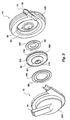
- FIG. 2 illustrates an exploded side view of the magnetically supported and rotated pumping apparatus of this invention.
- the exploded view shows the pump inlet 19, the first pump half 12, a bearing target 100 having a permanent magnet set 56, an impeller shroud 104, an impeller hub 108, an impeller inlet 112, permanent magnets 52 and 57, an impeller vane 116, a motor rotor 120 having a permanent magnet set 59, permanent magnets 54 and 58, the outlet vessel 15, and the pump outlet throughbore 16.
- spiral volute exit 18 is formed by the combination of first pump housing half 12 and second pump housing half 14, and sealed by hermetic seal 28.
- the configuration of the logarithmic spiral volute exit 18 of this invention utilizes a spiral volute curve formation to eliminate abrupt or harsh changes of direction to fluid flow during transportation from impeller to outlet vessel 15, thereby avoiding damage to sensitive fluids as described herein before.
- the combination of first pump housing half 12 and second pump housing half 14, together with hermetic seal 28, also forms containment for internal impeller 21 and impeller chambers 27a, 27b, 27c, and 27d (see FIG. 9), discussed hereafter in detail. Fluid flows entirely around impeller 21 via first return flow chamber 32 and second return flow chamber 34.
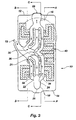
- FIG. 3 also shows an embodiment of a motor 40 that controls the rotational speed of the impeller 21.
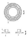
- FIGs. 4A and 4B depict a portion of the pump 10.
- FIG. 4A shows a plane view of section A (see FIG. 3) of the second pump housing half 14 and FIG. 4B shows a side view of section A of FIG. 3.
- Windings (or control coils) 52 and a bias coil 53 are shown that enable construction of the pump 10 by those skilled in the art.
- axial thrust bearings 45 that are controlled by an electronic controller.
- FIGs. 5A and 5B depict another portion of the pump 10, however, FIG. 5A shows a plane view of section B (see FIG. 3) of the first pump housing half 12 and FIG. 5B shows a side view of section B of FIG. 3.
- windings (or control coils) 52 and a bias coil 53 are shown that enable construction of the pump 10 by those skilled in the art.
- axial thrust bearings 48 that are controlled by an electronic controller.
- FIGs. 6A depicts section C of FIG. 3 in plane view to demonstrate the windings 84
- FIG. 6B shows a preferred embodiment of the stator 80 of the motor 40.
- the motor 40 will be described in greater detail hereinafter.
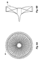
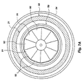
- FIG. 7A depicts section C of FIG. 3 in plane view to show the rotor or impeller 21 portion of the motor 40 and to demonstrate the arrangement of the permanent magnets 92 on the rotor.
- the magnets 92 are arcuately arranged and alternate north pole 91, south pole 93, north pole 91, south pole 93, etc. until the circular arrangement depicted in FIG. 7A is accomplished.
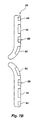
- FIG. 7B shows the same portion of the impeller (or rotor) 21 in cross-section. Also shown in both FIG. 7A and 7B is the permanent magnet ring 54, the permanent magnetic ring set 59, and magnetic material 55 that is the target of the axial thrust bearing.
- the rotor 21 will be described in greater detail hereinafter.
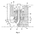
- FIG. 8 is an enlarged, fragmentary cross-sectional view of the pump impeller and housing of FIG. 1.
- FIG. 8 focuses on a portion of the cross-section view shown in FIG. 3 and provides greater clarity to the disclosure discussed relative to FIG. 3.
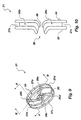
- Pump impeller 21 is configured with two or more impeller vanes 26a, 26b, 26c, and 26d, shown in FIG. 9, with a preferred embodiment of four impeller vanes 26a, 26b, 26c and 26d.
- Each impeller vane 26 is mounted between impeller shroud 22 and impeller hub 24 such that impeller chambers 27a, 27b, 27c and 27d are formed.
- Each impeller vane 26a, 26b, 26c and 26d corresponds to impeller chambers 27a, 27b, 27c, and 27d respectively.
- impeller vanes 26 are configured with a spiral curvature such that rotation of impeller 21 brings impeller vanes 26 in contact with fluid to be pumped, thereby causing fluid to move radially toward spiral volute exit 18.
- Rotation of impeller 21 centrifugally transports fluid from the region at the axial center of construct 10 toward the spiral volute exit 18, correspondingly creating a partial vacuum at the region of impeller intake opening 30 and drawing in additional fluid through intake vessel 19 (FIG. 1) .
- the impeller is designed to allow for a smooth transition of the flow vector from inlet to outlet. This is accomplished in one particular embodiment employing a blade angle of 17° at the base of the blade at the inlet, A.
- the blade angle is gradually decreased to 11° at the top of the blade at the inlet, B. Hence the blade is not straight in the axial direction near the inlet. The blade gradually transitions to being straight in the axial direction with an angle of 37° near the midpoint of the blade, C. This 37 o angle is maintained to the exit point, D. All blade angles are the inner angles of the blade relative to a tangent to a circle centered in the center of impeller 21.
- the pump volute is located in the pump stationary component to provide a smooth flow of pumped fluid from the discharge of the impeller at relatively high velocity into the pump exit passage where it is slowed down prior to exiting from the pump.
- the volute increases the fluid pressure (head) by converting fluid kinetic energy (velocity) to potential energy (pressure or head).
- the clearance around the impeller 21 in one particular embodiment is maintained at 0.030" to allow for good washing of the surfaces. Any changes in direction of the flow in the clearance passages are made by maximizing the radius of curvature in order to keep the flow laminar.
- impeller 21 a portion of fluid pumped by impeller 21 returns from the region of high pressure near spiral volute 18 along both sides of impeller 21, via first impeller return chamber 32 and second impeller return chamber 34, as reverse flow to region of lower pressure near impeller intake opening 30. Fluid returning along second impeller return chamber 34 also passes through impeller return opening 36, and thereby serves to equalize internal pressure.
- the width of impeller return chambers 32 and 34 are calculated by a precise balance of primary fluid flow and reverse flow, such that fluid does not stagnate within the pump but also does not possess unnecessary inefficiencies,
- Permanent magnet set 52 is a magnetic ring located at the practical circumference edge of first impeller disk 22 and is oriented with north poles proximal and south poles distal thereby utilizing the magnetic repulsive forces away from interior wall of first pump half 12.
- permanent magnet set 54 is a magnetic ring located at the practical circumference edge of second impeller disk 24, and is oriented with north poles proximal and south poles distal thereby utilizing magnetic repulsive force away for interior wall of second pump housing 14, but whose direction of force opposes permanent magnet set 52, such that impeller 21 is stabilized axially at the circumference of impeller 21.
- First housing permanent magnet set 56 and first impeller permanent magnet set 57 are configured in a double ring configuration located proximal to impeller intake opening 30, with alignment on either side of first return flow chamber 32, and are integral to first pump housing half 12 and first impeller disk 22, respectively.
- the reverse polarity of first housing permanent magnet set 56 and first impeller permanent magnet set 57 for each of the two magnetic rings enables radial stabilization and, due to the angular positioning, also provides a degree of translational stabilization of impeller 21.
- Second housing permanent magnet set 58 and second impeller permanent magnet set 59 are configured likewise in a double ring configuration and are proximal to return opening 36, with alignment on either side of second return flow chamber 34, and are integral to second pump housing half 14 and second impeller disk 24, respectively.
- the reverse polarity of second housing permanent magnet set 58 and second impeller permanent magnet set 59 enables radial stabilization of impeller 21 and a degree of translational stabilization of impeller 21.
- the double ring configuration of the magnetic sets is a double magnet reverse polarity design.
- the magnetic sets 56, 57, 58, and 59 are each located at approximately one-half the radial point of the impeller 21.
- the rings of each set are placed in an attractive orientation next to one another and the sets are placed in a reverse polarity from one another.
- the magnetic arrangement has the property of producing positive radial stiffness. If a fluid or other force tends to push the impeller 21 off center, the attractive forces between the NS and SN rings apply a radially centering force to prevent it.
- the radial stiffness is approximately 67,000 N/m.
- the two bearing sets have a combined radial stiffness of 134,000 N/m. This double ring arrangement has been shown to keep the impeller properly centered and operating during ventricular assist duty.
- the four sets of permanent magnet rings 56, 57, 58 and 59 provide a significant portion of the total suspension and stabilization of impeller 21 within pump housing half 12 with final stabilization, fine positioning and rotation of impeller 21 provided by electromagnetic thrust bearings 46 and 50, electric activation coils 44 and 48 and motor 40 with associated coils at 42 and 60.
- the magnetic suspension and rotation of impeller 21 provides a contact-free operation which increases overall product life and reliability and avoids sensitive fluid damage as discussed hereinbefore.
- the four magnetic rings as described above, each with reversed North and South magnetic polarities, are configured such that interacting magnetic fields produce positive radial and axial stiffness, which are necessary to counter radial and axial applied forces due to fluid, motor forces, gravitational load, acceleration forces, and other incidental forces.
- Electromagnetic thrust bearings 46 and 50 are comprised of stationary magnetic actuator components, electric activation coils 44 and 48, electronic controllers (not shown), power amplifiers (not shown), a means of sensing impeller 21 position, velocity or acceleration (not shown).
- An electronic controller (not shown) provides automatic adjustment to electrical current in electric activation coils 44 and 48, which change in electrical current adjusts the control forces exerted by electromagnetic thrust bearings 46 and 50.
- the electronic controller continuously provides electric signal input which relates to position, velocity and/or acceleration of the rotating impeller 21. Additional components necessary for operation of construct 10 are switching or direct current power amplifiers and power sapless (not shown).
- FIGs. 6A and 6B show a plane view and a cross-section view of a motor stator 80 of the motor 40.
- Motor 40 is a 3-phase brushless motor and provides electromagnetic force to start and rotate the pump impeller or rotor 21.
- the motor 40 consists of a permanent magnet rotor 21 with permanent magnets 92 imbedded in the hub of a centrifugal or mixed flow pump.
- the magnets 92 are wedge shaped and arranged to form a circular rotor.
- the magnets 92 are arranged such that magnetization of the permanent magnets alternate north and south polarities both radially and angularly around the rotor 21.
- the motor stator 80 has wire windings 84 excited by current from an electronic controller. This stator arrangement produces a magnetic field interacting with the permanent magnets 92 to produce a torque on the rotor 21.
- FIG. 6A and 6B shows an ironless configuration for the motor stator; stator 80 has no saturable magnetic material.
- wire 84 is wound on a separate fixture and fixed in place on rotor 80 using epoxy or similar material.
- the above configuration meets the unique criteria for a centrifugal or mixed flow medical device pump that is needed as was discussed in the background section.
- the use of permanent magnets in the rotor results in no mechanical contact between the rotor and stator of the motor.
- the electromagnetic bearing sets 52, 54, 56, 57, 58 and 59 allow the rotor/impeller 21 to rotate with complete lack of contact with the stator 80.
- the geometry of the motor meets the requirements of allowing the motor to drive the pump in an efficient manner while providing for laminar flow in the flux gaps with minimal stagnation of blood. This is realized by keeping bending radii large.
- FIG. 13 shows the coordinate system for defining impeller 21 magnetic actuation in the required six directions: three translations (x,y,z) and three rotations ( ⁇ , ⁇ , ⁇ ) . All three translational displacements (x,y,z) and two rotations (pitching motions about two axes) ( ⁇ , ⁇ ) are held nearly fixed in space relative to the stator by the magnetic forces. The last rotation actuation ( ⁇ ) , about the z axis rotation, is accomplished by the motor.
- the magnetic bearings are constructed in two parts: 1) a thrust/moment configuration and a 2) radial/thrust configuration.
- a thrust/moment configuration and a 2 radial/thrust configuration.
- permanent magnets are used with the activation coils and are placed in pairs so that there are four quadrants of control. This provides a combination of axial actuation (z) and pitching moments ( ⁇ , ⁇ ).
- the thrust force (z) is generated so that each magnetic pole in the arrangement exerts the same force on the target.
- the pitching angular actuation forces are also produced by the permanent magnets above and below the impeller centerline ( ⁇ angular displacement) and to the left and right of the impeller ( ⁇ angular displacement).
- the function of the electronic controller is to determine what combination of currents must be employed to fine tune these axes, i.e., provide final stabilization and fine. positioning and rotation.
- the axial thrust bearings are the only electronically controlled bearings in this embodiment of the invention.
- this magnetic bearing configuration can exert control forces in the axial direction (z), radial directions (x,y), and angular displacements ( ⁇ , ⁇ ). These two magnetic bearing configurations, the thrust/moment and the radial/thrust configurations, produce the necessary magnetic forces and moments required to keep the impeller centered and under control.
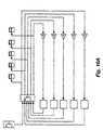
- FIGs. 16A and 16B show an embodiment of the electronic circuits for electronic feedback control of the impeller position within the stator clearance region.
- these electronic circuits apply to the axial thrust bearing only because the axial thrust bearing is the only set of coils electronically controlled.
- Electronic circuits composed of resistors, capacitors, amplifiers, etc. are combined to control the impeller dynamics using proportional-integral-derivative control methods or other linear control algorithms such as state space, mu synthesis, linear parameter varying control, and nonlinear control algorithms such as sliding mode control.
- Particular control algorithms are used to take into account impeller rigid body gyroscopic forces, fluid stiffness, damping and inertia properties whose magnitude depend upon impeller position, rotational rate, pressure rise, and flow rate.
- the physical circuits are miniaturized using surface mount technology, very large scale integrated (VLSI) circuit design and other means.
- VLSI very large scale integrated
- control algorithm produces the eight coil currents which control the three displacements (x,y,z) and two angular displacements ( ⁇ , ⁇ ) .
- the controller algorithm design is robust to account for uncertainties in forces acting on the impeller such as fluid stiffness, damping and inertia properties, gyroscopic effects, magnetic forces, etc.
- the control algorithms are implemented on a dedicated microprocessor with adjustable parametric- variation implementation to account for different physiological needs for the different applications to different size humans, from children to large adults.
- Power amplifiers are employed in the invention to produce the desired coil currents for the electromagnetic bearings as determined by the electronic controller output voltage.
- One embodiment of a switching amplifier, operating with voltage switched either on or off at a frequency much higher than the rotational frequency of the pump impeller, is utilized in the device because power amplifiers are very efficient, having an efficiency in the range of 85 to 99%.
- the electronic power circuits are composed of magnetic coils, with associated resistance and inductance, resistors, capacitors, semiconductor components. The coils are implemented using wire with low resistance.
- These power circuits are designed to be regenerative - that is, the magnetic bearing enabling power moves back and forth between the magnetic coil inductors to the capacitors with the only losses occurring due to the low coil resistance (ohmic losses).
- the high power present in the magnetic coil circuits is a small fraction of the nominal power capability; the nominal power capability being defined as supply voltage times average switched current in the coils.
- the invention is designed to generate the electronic signal related to the position, velocity or acceleration of the rotating impeller through one of the following: (i) a physical device such as an eddy current, induction, optical, capacitance or other approach; or (ii) a combination of the current and voltage waveform provided to the activating coils in the magnetic bearings.
- a physical device such as an eddy current, induction, optical, capacitance or other approach
- a combination of the current and voltage waveform provided to the activating coils in the magnetic bearings.
- the electronic position, velocity, or acceleration signal is obtained from signal conditioning electronics and wiring provided for input of the signal into the electronic controller for the magnetic bearings.
- the signal conditioning is provided for determining the position, velocity, or acceleration of the rotating impeller without a physical device, which allows for a minimum number of wires required in the wiring pathways between the electromagnetic actuators and the electronic controllers.
- a preferred embodiment of the sensing function of the invention is the self sensing configuration.
- the self sensing configuration avoids the use of a physical sensor in the stator, minimizes the size of the pump, and minimizes the number of wires required for operation.
- position sensing is accomplished by examining the voltage and current switching wave forms (employed with the switching power amplifiers described above) for several of the electromagnetic coils. Each coil is driven by a switching power amplifier with a high (in the kHz range) carrier frequency.
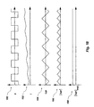
- the resulting current waveform one version which is shown in FIG. 18, is a combination of the relatively low frequency commanded waveform (to produce the necessary control force for positioning the impeller) and a high frequency triangular waveform due to the high frequency carrier.
- the amplitude (magnitude) of this commanded waveform is a function of the circuit inductance (a combined inductance due to the magnetic material properties in the magnetic bearing and due to the fluid gap), the switching frequency, the power supply voltage, and the duty cycle of the switching amplifier (ratio of on to off voltage employed in amplifier to produce the desired control forces).
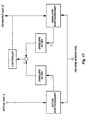
- FIG. 17 shows an embodiment of electronic filters that are provided in the self sensing part of the invention to extract the fluid gap dimension information while removing the effects of power supply voltage, switching frequency, duty cycle variation, and electronic or magnetic noise.
- a parameter estimation method is employed to demodulate the signal and determine the fluid gap dimension.
- One embodiment of the envelope of filters is employed, consisting of a high pass filter to remove the bias current, a precision rectifier to make the waveform strictly positive, and a low pass filter to remove the variation in the remaining signal.
- the embodiments shown in FIG. 17 gives a low noise sensor with a high bandwidth, suitable for the self sensing signal determination of the fluid gap dimension.
- FIG. 18 shows the sequence of signal forms as they pass through the filters: the graph at 180 shows the supply coil voltage, the graph at 182 shows a typical actual coil current waveform, the graph at 184 shows the current signal output from the integrator (described in detail in FIG. 19) which removes the change in coil current due to the control of the externally imposed forces and moments, the graph at 186 shows the rectified version of 184, and the graph at 188 shows the time average of 186 extracted using a low pass electronic filter.
- the integrator described in detail in FIG. 19
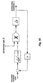
- FIG. 19 shows a circuit which extracts the change in coil current due to the control of the externally imposed forces and moments.
- a negative feedback circuit which comprises an integrator whose gain is controlled by an analog multiplier indexed to the estimated gap.
- This feedback circuit includes a proportional-integral device where the estimated displacement and the integral of the estimated displacement are combined to form the negative feedback signal and then compared to the original voltage waveform to provide the desired current waveform proportional to the impeller displacement.
- bias currents are not created that will produce high heat generation. Bias current is not desirable for use in human sensitive fluids such as blood.
- the axial thrust bearing is the one set of coils that uses the self sensing electronic controller and thus, hardware, circuit complexity, and wiring are all reduced along with the reduction in heat from bias currents.
- the use of pumps for sensitive applications often requires adjustment of flow rates and pressure rises such as in the artificial heart where the physiological conditions change significantly.
- the rotational speed must never be so high as to cause excessive suction that can lead to inflow vessel collapse.
- the body may be resting or sleeping with a rather low required flow rate and pressure rise whereas if the body is undergoing exercises, such as walking, a much higher flow rate and pressure rise is required.
- the primary method of adjusting the flow rate and pressure rise is by varying the motor speed.
- the axial thrust bearings are the only set of coils (or magnetic forces) that are electrically controlled.
- a second embodiment of the physiological controller uses an indirect measurement of pressure rise from the inlet of the pump to the outlet of the pump (i.e., Pout - Pin).
- Pout - Pin a measurement of pressure rise from the inlet of the pump to the outlet of the pump.
- Change in systemic resistance is known to be one indicator of increased physical exertion in humans.
- a measurement of pressure difference from outlet to inlet is used as a basis for a physiological controller.
- the measurement of pressure difference from inlet to outlet can be indirectly measured by two methods which are (1) measurement of motor current and pump speed, or (2) measurement of bearing current, or some combination thereof.
- the pump inlet pressure is called the preload while the pump exit pressure is called the afterload.
- the first method to measure pressure indirectly uses measurements of motor current and pump speed. These measurements are used in an electronic controller to derive pressure based on equations and/or tables electronically stored in the controller. The relationship between current, speed, and pressure rise is characterized and calibrated prior to operation, providing the basis for the controller.
- the block diagram for the implementation of the controller is shown in FIG. 20.
- the second method to measure pressure rise indirectly uses magnetic bearing current. It is well known that current in an active magnetic bearing is directly proportional to force on the rotor. The pressure difference from outlet to inlet of the pump can be derived directly from the resultant net force on the impeller due to the pressure difference. Hence, the bearing current can be used in an electronic controller to derive the pressure difference from outlet to inlet of the pump.
- the block diagram of the implementation of the controller is shown in FIG. 21.
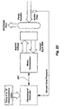
- FIG. 22 shows another embodiment of a physiological electronic feedback control circuit that is provided in the invention to regulate the motor speed relative to the preload and afterload signals thereby properly controlling the motor speed.
- the physiological control circuit is provided to regulate the pump flow rate and pressure rise to meet the physiological needs of the biological application.
- Reference number 220 indicates an interface between the physiological controller and the motor commutator such that a desired speed signal is sent to the motor commutator and an actual speed signal is sent to the physiological controller.
- the embodiment of FIG. 22 illustrates motor control based on physiological parameters.
- the electronic signals from the activating coil currents in the electromagnetic bearings are related to other forces such as the gravitational loading and acceleration effects relating to the beginning of motion and the stopping of motion.
- electronic signals related to the acceleration are obtained by sensing, either in the pump housing or other location of known position relative to the pump, the acceleration in one, two, or three orthogonal directions. The electronic acceleration signals are then employed in the invention to subtract that signal from the preload and afterload signals, as described above. The resulting difference signal is then used for the physiological controller described above.
- the speed of the motor is related to the physiological performance of the pump.
- the motor feedback emf is used to sense the rotational speed of the motor rotating about the pump impeller axis and to develop an electronic signal proportional to the impeller rotational speed.
- the impeller rotational speed signal is provided to the electronic physiological feedback controller described above.
- the present motor rotational speed is used in combination withe the preload and afterload signals to adjust future motor speeds to match physiological pump flow rate and pressure rise needs based upon body requirements and to avoid undue suction.
- Elements of construct 10 are operable in singular mode as a ventricular assist device, or paired for a total artificial heart. In the case of the total artificial heart which utilizes two of construct 10, each construct 10 operates entirely independent of the other construct, thereby eliminating complex control equipment and circuits that would otherwise be required if both constructs were combined.
- the physiologic controller senses fluid pressure inside intake vessel 19 and generates an electrical signal to modify rotational speed of motor 40 according to specific algorithms determined by electronic controller (not shown).
- the physiologic controller may signal a change in rotational speed of motor 40 to compensate for a change in fluid pressure inside intake vessel 19 yet avoid excessive rotational motor speed that would collapse vessels.
- the physiologic controller (not shown) senses position, velocity, and/or acceleration information of impeller 21 via eddy current, induction, optical, capacitance or other self-sensing electronic signals and generates an electrical signal that is sent to the electronic controller (not shown), which correspondingly provides adjustment to electrical current in electric activation coils 44 and 48, thereby providing adjustment to control forces exerted by electromagnetic thrust bearings 46 and 50. Adjustments to electromagnetic thrust bearings 46 and 50 compensates for applied forces due to fluid, motor forces, gravitational load, acceleration forces, and other incidental forces.
- impeller 21 brings impeller vanes 26 in contact with fluid to be pumped, thereby causing fluid to move radially toward spiral volute exit 18.
- the centrifugal transport of fluid from the region at the axial center of construct 10 toward the spiral volute exit 18 correspondingly creates a partial vacuum at the region of impeller intake opening 30 and draws in additional fluid through intake vessel 19.
- the unique log spiral configuration of spiral volute exit 18 then transports sensitive fluid along the region near the circumference of construct 10 in a smooth, non-turbulent and low thermal manner to outlet vessel 15.
- Outlet vessel 15 is connected to anatomical vessels or other mechanisms.
- a portion of fluid pumped by impeller 21 returns from the region of high pressure near spiral volute 18 along both sides of impeller 21, via first impeller return chamber 32 and second impeller return chamber 34, in the form of reverse fluid flow to the region of lower pressure near impeller intake opening 30. Fluid returning along second impeller return chamber 34 also passes through impeller return opening 36, and thereby serves to equalize internal fluid pressures and prevent flow in the clearance passages from sensitive fluid stagnation.
- rotational speed of impeller 21 is varied and controlled by the electronic controller (not shown), which adjust electrical current in motor 40, thereby accelerating and decelerating the rotation of impeller 21 and causing fluid to be pumped in a pulsatile fashion.
Landscapes
- Health & Medical Sciences (AREA)
- Engineering & Computer Science (AREA)
- Heart & Thoracic Surgery (AREA)
- Mechanical Engineering (AREA)
- Cardiology (AREA)
- Hematology (AREA)
- Animal Behavior & Ethology (AREA)
- Veterinary Medicine (AREA)
- Anesthesiology (AREA)
- Biomedical Technology (AREA)
- Public Health (AREA)
- Life Sciences & Earth Sciences (AREA)
- General Health & Medical Sciences (AREA)
- General Engineering & Computer Science (AREA)
- Physics & Mathematics (AREA)
- Electromagnetism (AREA)
- Medical Informatics (AREA)
- Structures Of Non-Positive Displacement Pumps (AREA)
- External Artificial Organs (AREA)
- Centrifugal Separators (AREA)
- Other Liquid Machine Or Engine Such As Wave Power Use (AREA)
Claims (21)
- Vorrichtung zum Pumpen sensitiver biologischer Fluide, aufweisend:gekennzeichnet durch:eine Baugruppe (10) mit einem Äußeren, einem hohlen Inneren, in dem Wände angebaut sind, zumindest einem darin angeordneten Gehäuse-Permanentmagneten und einem axialen Zentrum;einen Einlass (19), der von dem Baugruppen-Äußeren zum Durchtritt von Fluiden und in das hohle Baugruppen-Innere gebildet ist;einen Auslass (15), der von dem Baugruppen-Äußeren zum Durchtritt von Fluiden aus dem hohlen Baugruppen-Inneren gebildet ist, wobei der Auslass radial von dem axialen Zentrum der Baugruppe angeordnet ist; undin dem hohlen Baugruppen-Inneren und ohne Kontakt mit der Baugruppe angeordnete Pumpenrademittel (21) zum Steuern der Fluidströmung in den Einlass, durch das hohle Baugruppen-Innere und aus dem Auslass, wobei die Pumpenradmittel gekrümmte Schaufeln und gekrümmte Durchlässe aufweisen, wodurch eine Fluidströmung durch die Baugruppe graduell von dem Einlass zu dem Auslass umgelenkt wird;eine magnetische Einrichtung mit mehreren elektromagnetischen Stellgliedern, die sechs Steuerachsen, einschließlich (i) einer axialen Translationsachse, (ii) zwei radialer Translationsachsen und (iii) drei Drehachsen bilden, von denen zwei Achsen momentengesteuert und eine Achse durch Motordrehung gesteuert sind, wobei wenigstens eine der momentengesteuerten, durch axiale und durch radiale Translation gesteuerten fünf Achsen von einem Satz von Permanentmagneten (52, 54 und 58), die in dem Gehäuse auf einer Achse parallel zur Drehachse der Pumpenradmittel magnetisiert sind, und ferner zumindest einen dem Gehäuse-Permanentmagneten gegenüberliegenden Pumpenrad-Permanentmagneten umfasst, um die Pumpenradmittel schwebend außer Kontakt mit dem hohlen Baugruppen-Inneren zu halten; undein Motormittel (40) zum selektiven Drehen der Pumpenradmittel, um dadurch eine Fluidströmung durch die Vorrichtung zu steuern.
- Vorrichtung nach Anspruch 1, wobei die Pumpenradmittel eine integrale Kombination eines der Fluidströmung durch die Baugruppe dienenden Pumpenrads und eines von dem Motormittel gesteuerten Rotors aufweist, was dem Motormittel eine Drehbewegungssteuerung der Pumpenradmittel ermöglicht, wobei die integrale Kombination des Pumpenrades und des Rotors Innenseiten einer ersten Rückflusskammer bzw. einer zweiten Rückflusskammer bildet, um eine Fluidströmung um die schwebend gehaltenen Pumpenradmittel zu ermöglichen.
- Vorrichtung nach Anspruch 2, wobei die Innenseite des die erste Rückflußkammer bildenden Pumpenrades ein erstes Bauteil mit einer Krümmung umfaßt, die einer Krümmung von Wänden des hohlen Baugruppen-Inneren entspricht.
- Vorrichtung nach Anspruch 3, wobei das erste Bauteil einen ersten Pumpenrad-Permanentmagneten zur Wechselwirkung mit einem ersten Gehäuse-Permanentmagneten und einen ersten Pumpenrad-Permanentmagnetsatz zur Wechselwirkung mit einem ersten Gehäuse-Permanentmagnetsatz aufweist, wobei (i) der erste Pumpenrad-Permanentmagnet derart dem ersten Gehäuse-Permanentmagneten gegenüberliegend angeordnet ist, dass ein Pol des ersten Pumpenrad-Permanentmagneten einen Pol des ersten Gehäuse-Permanentmagneten abstößt und (ii) der erste Pumpenrad-Permanentmagnetsatz derart dem ersten Gehäusepermanentmagnetsatz überliegend angeordnet ist, dass Pole des ersten Pumpenrad-Permanentmagnetensatzes Pole des ersten Gehäuse-Permanentmagnetensatzes abstoßen, wodurch ein Kontakt zwischen dem ersten Element und dem Gehäuse verhindert wird.
- Vorrichtung nach Anspruch 4, wobei der erste Pumpenrad-Magnetsatz und der erste Gehäuse-Magnetsatz jeweils eine doppelte Ringanordnung um das Pumpenrad bzw. das Gehäuse aufweisen, wobei die doppelte Ringanordnung jedes Magnetsatzes einen ersten Magnetring und einen in einer anziehenden Orientierung mit dem ersten Magnetring angeordneten zweiten Magnetring aufweist und wobei der erste Pumpenrad-Magnetsatz in umgekehrter Polarität zu dem ersten Gehäusemagnetsatz angeordnet ist.
- Vorrichtung nach Anspruch 3, wobei das erste Bauteil ein erstes magnetisches Material zur Wechselwirkung mit (i) einem ersten elektromagnetischen Drucklager und (ii) einer ersten elektrischen Aktivierungsspule aufweist, wobei das erste elektromagnetische Drucklager und die erste elektrische Aktivierungsspule die Pumpenradmittel stabilisieren und Mittel zum Steuern einer Kombination aus einer axialen Stellung, zwei Winkelverschiebungs-Freiheitsgraden, externen Druckkräften und auf die Pumpenradmittel einwirkenden externen Momenten ermöglichen.
- Vorrichtung nach Anspruch 2, wobei die die zweite Rückflusskammer bildende Innenseite des Rotors ein zweites Bauteil mit einer Krümmung umfasst, die einer Krümmung von Wänden des hohlen Baugruppen-Inneren entspricht, das zweite Bauteil mit einem ersten Bauteil durch die gekrümmten Schaufeln der Pumpenradmittel verbunden ist, wodurch Pumpenradkammern von (i) den gekrümmten Schaufeln, (ii) dem ersten Bauteil und (iii) dem zweiten Bauteil gebildet werden, wodurch die gekrümmten Durchlässe für die graduelle Umlenkung von Fluid aus dem Einlass zu dem Auslass gebildet werden.
- Vorrichtung nach Anspruch 7, wobei das zweite Bauteil einen zweiten Pumpenrad-Permanentmagneten zur Wechselwirkung mit einem zweiten Gehäuse-Permanentmagneten und einen zweiten Pumpenrad-Permanentmagnetsatz zur Wechselwirkung mit einem zweiten Gehäuse-Permanentmagnetsatz aufweist, wobei (i) der zweite Pumpenrad-Permanentmagnet dem zweiten Gehäuse-Permanentmagneten derart gegenüberliegt, dass ein Pol des zweiten Pumpenrad-Permanentmagnets einen Pol des zweiten Gehäuse-Permanentmagneten abstößt und (ii) der zweite Pumpenrad-Permanentmagnetsatz dem zweiten Gehäuse-Permanentmagnetsatz derart gegenüberliegt, dass Pole des zweiten Pumpenrad-Permanentmagnetsatzes Pole des zweiten Gehäuse-Permanentmagnetsatzes abstoßen, wodurch ein Kontakt zwischen dem zweiten Bauteil und dem Gehäuse verhindert wird.
- Vorrichtung nach Anspruch 8, wobei der zweite Pumpenrad-Permanentmagnetsatz und der zweite Gehäuse-Permanentmagnetsatz jeweils eine doppelte Ringanordnung um das Pumpenrad bzw. das Gehäuse aufweisen, wobei die doppelte Ringanordnung jedes Magnetsatzes einen ersten Magnetring und einen in einer anziehenden Orientierung zu dem ersten Magnetring angeordneten zweiten Magnetring aufweist und der zweite Pumpenrad-Magnetsatz in umgekehrter Polarität zu dem zweiten Gehäuse-Permanentmagnetsatz angeordnet ist.
- Vorrichtung nach Anspruch 7, wobei das zweite Bauteil ein zweites magnetisches Material zur Wechselwirkung mit einem zweiten elektromagnetischen Drucklager und einer zweiten magnetischen Aktivierungsspule aufweist, wobei das zweite elektromagnetische Drucklager und die zweite elektrische Aktivierungsspule die Pumpenradmittel stabilisieren und eine Kombination von zwei Freiheitsgraden in radialer Position, axialer Position, externen Radialkräften und externen auf die Pumpenradmittel einwirkenden Druckkräften steuert.
- Vorrichtung nach Anspruch 7, wobei das zweite Bauteil einen integral eingebauten Rotor aufweist und der Rotor eine Mehrzahl von daran angeordneten Permanentmagneten zur Wechselwirkung mit den Motormitteln umfasst, wobei der Rotor von den Motormitteln gedreht werden kann und dadurch die Pumpenradmittel dreht.
- Vorrichtung nach Anspruch 1, wobei die Magneteinrichtung eine Anordnung aufweist, auswobei die Anordnung eine radiale Stabilisierung und aufgrund der Winkelposition einen Translationsstabilisierungsgrad der Pumpenradmittel zur Verfügung stellt, und die Pumpenradmittel durch Magnetfelder daran gehindert sind, mit dem hohlen Baugruppen-Inneren in Kontakt zu kommen.einem an einer ersten Wand des hohlen Baugruppen-Inneren angeordneten ersten Baugruppen-Permanentmagneten,einem an einer zweiten Wand gegenüber der ersten Wand des hohlen Baugruppen-Inneren angeordneten zweiten Baugruppen-Permanentmagneten,einem ersten Pumpenrad-Permanentmagneten, der entfernt von dem axialen Zentrum der Baugruppe und dem ersten Baugruppen-Permanentmagneten gegenüberliegend an den Pumpenradmitteln angeordnet ist,einem zweiten Pumpenrad-Permanentmagneten, der entfernt von dem axialen Zentrum der Baugruppe und dem zweiten Baugruppen-Permanentmagneten gegenüberliegend an den Pumpenradmitteln angeordnet ist,einem an der ersten Wand des hohlen Baugruppen-Inneren angeordneten Baugruppen-Permanentmagnetsatz,einem an der zweiten Wand des hohlen Baugruppen-Inneren angeordneten zweiten Bauelement-Permanentmagnetsatz,einem ersten Pumpenrad-Permanentmagnetsatz, der in der Nähe des axialen Zentrums der Baugruppe und dem ersten Baugruppen-Permanentmagnetsatz gegenüberliegend an den Pumpenradmitteln angeordnet ist, undeinem zweiten Pumpenrad-Permanentmagnetsatz, der in der Nähe des axialen Zentrums der Baugruppe und an dem zweiten Baugruppen-Permanentmagnetensatz gegenüberliegend an den Pumpenradmitteln angeordnet ist,
- Vorrichtung nach Anspruch 12, wobei die Magneteinrichtung aufweist:zumindest eine in der ersten Wand des Baugruppengehäuses angeordnete Spule und zumindest eine weitere in der zweiten Wand des Baugruppengehäuses angeordnete Spule, wobei die zumindest eine Spule in Juxtaposition zwischen (i) dem ersten Baugruppen-Permanentmagneten und (ii) dem ersten Baugruppen-Permanentmagnetsatz angeordnet ist, und die zumindest eine weitere Spule in Juxtaposition zwischen (i) dem zweiten Baugruppen-Permanentmagneten und (ii) dem zweiten Bauelement-Permanentmagnetsatz angeordnet ist,zumindest ein elektromagnetisches, in dem Baugruppengehäuse um die zumindest eine Spule und die zumindest eine weitere Spule angeordnetes Drucklager, undeinen elektronischen Controller zum Steuern des elektrischen Stroms in der zumindest einen Spule und der zumindest einen weiteren Spule, wobei Änderungen der von dem zumindest einen elektromagnetischen Drucklager ausgeübten Kräfte hervorgerufen werden.
- Vorrichtung nach Anspruch 13, wobei der elektronische Controller ein physiologisches Steuergerät zum Steuern einer Drehzahl des Pumpenrades derart aufweist, dass die Drehzahl dem physiologischen Zustand einer die erfindungsgemäße Vorrichtung verwendenden Person entspricht.
- Vorrichtung nach Anspruch 3, wobei die fünf Achsen der Pumpenradbewegung unter Verwendung eines Hybrid-Magnetlagersystems folgendermaßen gesteuert werden: der erste Pumpenrad-Radialmagnetlagersatz und der erste Gehäuse-Radialmagnetlagersatz weisen jeweils einen um das Pumpenrad und das Gehäuse angeordneten doppelten Permanentmagnetring auf, wobei die Polaritäten derart angordnet sind, dass positive Radialsteifigkeiten erzeugt werden, so dass das Pumpenrad in einer zentrierten Stellung relativ zu den zwei Radialverschiebungen arbeitet; der erste Pumpenrad-Magnetzielsatz und der erste elektromagnetische Gehäuselagersatz weisen elektromagnetische Lager auf, die die verbleibende Axialverschiebung und zwei Winkelverschiebungen derart steuern, dass das Pumpenrad in einer zentrierten Stellung, bezogen auf diese drei Achsen, arbeitet.
- Vorrichtung nach Anspruch 3, wobei die fünf Achsen der Pumpenradbewegung unter Verwendung eines Hybrid-Magnetlagersystems folgendermaßen gesteuert werden: der erste Pumpenrad-Radialmagnetlagersatz und der erste Gehäuse-Radialmagnetlagersatz weisen jeweils einen um das Pumpenrad und das Gehäuse angeordneten doppelten Permanentmagnetring auf, wobei die Polaritäten derart angeordnet sind, dass positive Radialsteifigkeiten erzeugt werden, und ein weiches Magneteisen wird an einer oder mehreren der Ringflächen verwendet, um den magnetischen Fluss zwischen den Permanentmagnetringen derart zu fokussieren, dass das Pumpenrad in einer zentrierten Stellung relativ zu den zwei Radialverschiebungen arbeitet; der erste Pumpenrad-Magnetzielsatz und der erste elektromagnetische Gehäuse-Lagersatz weisen elektromagnetische Lager auf, die die verbleibende Axialverschiebung und zwei Winkelverschiebungen derart steuern, dass das Pumpenrad in einer zentrierten Stellung, bezogen auf diese drei Achsen, arbeitet.
- Vorrichtung nach Anspruch 3, wobei die fünf Achsen der Pumpenradbewegung unter Verwendung eines Hybrid-Magnetlagersystems folgendermaßen gesteuert werden: der erste Pumpenrad-Radialmagnetlagersatz und der erste Gehäuse-Radialmagnetlagersatz weisen jeweils einen Satz von mehreren um das Pumpenrad und das Gehäuse angeordneten Permanentmagnetringen auf, wobei die Polaritäten derart angeordnet sind, dass positive Radialsteifigkeiten erzeugt werden, und ein weiches Magneteisen wird an einer oder mehreren der Ringflächen verwendet, um den magnetischen Fluss zwischen den Permanentmagnetringen derart zu fokussieren, dass das Pumpenrad in einer zentrierten Stellung relativ zu den zwei Radialverschiebungen arbeitet; der erste Pumpenrad-Magnetzielsatz und der erste elektromagnetische Gehäuse-Lagersatz weisen elektromagnetische Lager auf, die die verbleibende Axialverschiebung und zwei Winkelverschiebungen derart steuern, dass das Pumpenrad in einer zentrierten Stellung, bezogen auf diese drei Achsen, arbeitet.
- Vorrichtung nach Anspruch 3, wobei die fünf Achsen der Pumpenradbewegung unter Verwendung eines Hybrid-Magnetlagersystems folgendermaßen gesteuert werden: der erste Pumpenrad-Radialmagnetlagersatz und der erste Gehäuse-Radialmagnetlagersatz weisen jeweils einen Satz von Permanentmagnetringen oder Mehrfach-Permanentmagnetringe auf, die um das Pumpenrad und das Gehäuse angeordnet sind, wobei die Polaritäten derart angeordnet sind, dass positive Axialsteifigkeiten und positive Momentensteifigkeiten erzeugt werden, und ein weiches Magneteisen wird an einer oder mehreren der Ringflächen verwendet, um den magnetischen Fluss zwischen den Permanentmagnetringen derart zu fokussieren, dass das Pumpenrad in einer zentrierten Stellung relativ zu der Axialverschiebung und den beiden Winkelverschiebungen arbeitet; der erste Pumpenrad-Magnetzielsatz und der erste elektromagnetische Gehäuselagersatz weisen elektromagnetische Lager auf, die die verbleibende Axialverschiebung derart steuern, dass das Pumpenrad in einer zentrierten Stellung bezüglich dieser Achse arbeitet.
- Vorrichtung nach Anspruch 3, wobei die fünf Achsen der Pumpenradbewegung unter Verwendung eines Hybrid-Magnetlagersystems folgendermaßen gesteuert werden: der erste Pumpenrad-Radialmagnetlagersatz und der erste Gehäuse-Radialmagnetsatz weisen jeweils einen Satz von um das Pumpenrad und das Gehäuse angeordneten Mehrfach-Permanentmagnetringen auf,
wobei die Polaritäten derart angeordnet sind, dass positive Axialsteifigkeit und positive Momentensteifigkeiten erzeugt werden, und ein weiches Magneteisen wird an einer oder mehreren der Ringflächen verwendet, um den magnetischen Fluss zwischen den Permanentmagnetringen derart zu fokussieren, dass das Pumpenrad in einer zentrierten Stellung relativ zu der Axialverschiebung und den beiden Winkelverschiebungen arbeitet; der erste Pumpenrad-Magnetzielsatz und die elektromagnetischen Lager die verbleibenden zwei Radialverschiebungen derart steuern, dass das Pumpenrad in einer zentrierten Stellung, bezogen auf diese beiden Achsen, arbeitet. - Eine Durchflusspumpe zum Pumpen sensitiver biologischer Fluide, aufweisend:gekennzeichnet durch:eine Baugruppe (10) mit einer ersten Pumpengehäusehälfte (12) und einer hermetisch mit der ersten Pumpengehäusehälfte abgedichteten zweiten Pumpengehäusehälfte (14), welche die Baugruppe bilden, wobei die Baugruppe ein hohles Inneres und ein axiales Zentrum hat;eine Pumpeneinlasskammer (19), die von der ersten Pumpengehäusehälfte gebildet ist und eine Einlass-Durchgangsöffnung zum Durchtritt von Fluiden durch den Einlass und in das hohle Baugruppen-Innere aufweist;eine Pumpenauslasskammer (15), die radial von dem axialen Zentrum der Baugruppe angeordnet ist und von den ersten und zweiten Pumpengehäusehälften gebildet ist und eine Auslass-Durchgangsöffnung zum Durchlass von Fluiden aus dem hohlen Baugruppen-Inneren aufweist; undein Pumpenradmittel (21), das in dem hohlen Baugruppen-Inneren und berührungslos angeordnet ist, und eine Pumpenradeinlassöffnung, Pumpenradkammern und die Pumpenradkammern bildende Pumpenradschaufel mit einer spiralförmigen Krümmung aufweist, wobei das Pumpenradmittel eine Fluidströmung in die Pumpeneinlasskammer, durch das hohle Baugruppen-Innere und aus der Pumpenauslasskammer steuert;eine magnetische Einrichtung mit einer Mehrzahl von elektromagnetischen Stellgliedern, die sechs Steuerachsen bereitstellen, einschließlich (i) einer axialen Translationsachse, (ii) zwei radialer Translationsachsen und (iii) drei Drehachsen, von denen zwei Achsen momentengesteuert und eine Achse durch Motordrehung gesteuert sind, wobei zumindest eine der momentengesteuerten, durch axiale Translation und durch radiale Translation gesteuerten fünf Achsen von einem Satz von Permanentmagneten (52, 54 und 58), die in dem Gehäuse auf einer Achse parallel zur Drehachse des Pumpenradmittels magnetisiert werden, gesteuert ist, und ferner mit zumindest einem dem Gehäuse-Permanentmagneten gegenüberliegenden Pumpenrad-Permanentmagneten, um das Pumpenradmittel außer Kontakt mit dem hohlen Baugruppen-Inneren schwebend zu halten und um das Pumpenradmittel zum Steuern des die Durchflusspumpe durchströmenden Fluids selektiv zu drehen; undein Motormittel (40) zum Steuern der Drehzahl des Pumpenradmittels.
- Ein Verfahren zum Pumpen sensitiver biologischer Fluide unter Verwendung einer Pumpe, enthaltend die folgenden Schritte:gekennzeichnet durch:Auswählen einer Pumpenvorrichtung mit einem magnetisch schwebend gehaltenen Pumpenrad in einem Gehäuse der Pumpe mit zumindest einem darin angeordneten Permanentmagneten, wobei das Pumpenrad gekrümmt ausgebildete Schaufeln zum Reduzieren einer Einwirkung auf die die Pumpe durchströmenden sensitiven Fluide aufweist; undPositionieren des Pumpenrades in dem Gehäuse in Abhängigkeit von Signalen die von magnetischen Mitteln, die das Pumpenrad magnetisch schwebend halten, aufgenommen werden;Steuern einer Mehrzahl von elektromagnetischen Stellgliedern zum Bereitstellen von sechs Steuerachsen einschließlich (i) einer axialen Translationsachse, (ii) zwei radialer Translationsachsen und (iii) drei Drehachsen, die zwei momentengesteuerte Achsen und eine durch Motordrehung gesteuerte Achse aufweisen;Positionieren der elektromagnetischen Stellglieder derart, dass zumindest eine der momentengesteuerten, durch axiale Translation und durch radiale Translation gesteuerten fünf Achsen durch einen Satz von zu einer Achse parallel der Drehachse der Pumpenradeinrichtung in dem Gehäuse magnetisierten Permanentmagneten gesteuert wird; undEinstellen der Pumpenrad-Drehzahl und somit der Fluid-Strömungsgeschwindigkeit nach Maßgabe von Signalen,die von einem Eingang und einen Ausgang der Pumpe empfangen werden.
Applications Claiming Priority (3)
| Application Number | Priority Date | Filing Date | Title |
|---|---|---|---|
| US1685696P | 1996-05-03 | 1996-05-03 | |
| US16856P | 1996-05-03 | ||
| PCT/US1997/007566 WO1997042413A1 (en) | 1996-05-03 | 1997-05-05 | Hybrid magnetically suspended and rotated centrifugal pumping apparatus and method |
Publications (3)
| Publication Number | Publication Date |
|---|---|
| EP0897476A1 EP0897476A1 (de) | 1999-02-24 |
| EP0897476A4 EP0897476A4 (de) | 2001-05-16 |
| EP0897476B1 true EP0897476B1 (de) | 2003-10-15 |
Family
ID=21779360
Family Applications (1)
| Application Number | Title | Priority Date | Filing Date |
|---|---|---|---|
| EP97922666A Expired - Lifetime EP0897476B1 (de) | 1996-05-03 | 1997-05-05 | Elektromagnetisch gelagerte und angetriebene kreiselpumpe und verfahren |
Country Status (11)
| Country | Link |
|---|---|
| US (2) | US6074180A (de) |
| EP (1) | EP0897476B1 (de) |
| JP (1) | JP2000510928A (de) |
| KR (1) | KR20000010735A (de) |
| CN (1) | CN1226307A (de) |
| AT (1) | ATE252203T1 (de) |
| AU (1) | AU735578B2 (de) |
| BR (1) | BR9709047A (de) |
| CA (1) | CA2253435C (de) |
| DE (1) | DE69725565T2 (de) |
| WO (1) | WO1997042413A1 (de) |
Cited By (4)
| Publication number | Priority date | Publication date | Assignee | Title |
|---|---|---|---|---|
| WO2009003027A1 (en) * | 2007-06-27 | 2008-12-31 | Brooks Automation, Inc. | Commutation of an electromagnetic propulsion and guidance system |
| US8680803B2 (en) | 2007-07-17 | 2014-03-25 | Brooks Automation, Inc. | Substrate processing apparatus with motors integral to chamber walls |
| US9024488B2 (en) | 2007-06-27 | 2015-05-05 | Brooks Automation, Inc. | Robot drive with magnetic spindle bearings |
| US9752615B2 (en) | 2007-06-27 | 2017-09-05 | Brooks Automation, Inc. | Reduced-complexity self-bearing brushless DC motor |
Families Citing this family (188)
| Publication number | Priority date | Publication date | Assignee | Title |
|---|---|---|---|---|
| US5840070A (en) | 1996-02-20 | 1998-11-24 | Kriton Medical, Inc. | Sealless rotary blood pump |
| US6302661B1 (en) * | 1996-05-03 | 2001-10-16 | Pratap S. Khanwilkar | Electromagnetically suspended and rotated centrifugal pumping apparatus and method |
| US6074180A (en) | 1996-05-03 | 2000-06-13 | Medquest Products, Inc. | Hybrid magnetically suspended and rotated centrifugal pumping apparatus and method |
| US6394769B1 (en) * | 1996-05-03 | 2002-05-28 | Medquest Products, Inc. | Pump having a magnetically suspended rotor with one active control axis |
| AUPO902797A0 (en) * | 1997-09-05 | 1997-10-02 | Cortronix Pty Ltd | A rotary blood pump with hydrodynamically suspended impeller |
| JP3382627B2 (ja) * | 1997-07-16 | 2003-03-04 | 三菱重工業株式会社 | モータ駆動高速回転体駆動制御装置と該駆動制御装置に使用される機種判別方法 |
| US6250880B1 (en) * | 1997-09-05 | 2001-06-26 | Ventrassist Pty. Ltd | Rotary pump with exclusively hydrodynamically suspended impeller |
| US6889082B2 (en) | 1997-10-09 | 2005-05-03 | Orqis Medical Corporation | Implantable heart assist system and method of applying same |
| AUPP240198A0 (en) * | 1998-03-17 | 1998-04-09 | Resmed Limited | An apparatus for supplying breathable gas |
| KR20010071171A (ko) | 1998-04-22 | 2001-07-28 | 톰 메이져 | 하이브리드 자기 베어링을 갖춘 이식가능한 원심 혈액펌프 |
| DE59915262D1 (de) * | 1998-07-10 | 2011-06-01 | Levitronix Llc | Verfahren zur Bestimmung des Druckverlustes und des Durchflusses durch eine Pumpe |
| DE29821565U1 (de) * | 1998-12-02 | 2000-06-15 | Impella Cardiotechnik AG, 52074 Aachen | Lagerlose Blutpumpe |
| US6416215B1 (en) | 1999-12-14 | 2002-07-09 | University Of Kentucky Research Foundation | Pumping or mixing system using a levitating magnetic element |
| AUPP995999A0 (en) * | 1999-04-23 | 1999-05-20 | University Of Technology, Sydney | Non-contact estimation and control system |
| DE60021554T2 (de) * | 1999-04-23 | 2006-03-30 | Ventrassist Pty Ltd., Brisbane | Rotationsblutpumpe sowie kontrollsystem dafür |
| US6234772B1 (en) | 1999-04-28 | 2001-05-22 | Kriton Medical, Inc. | Rotary blood pump |
| US6227820B1 (en) * | 1999-10-05 | 2001-05-08 | Robert Jarvik | Axial force null position magnetic bearing and rotary blood pumps which use them |
| US6758593B1 (en) | 2000-10-09 | 2004-07-06 | Levtech, Inc. | Pumping or mixing system using a levitating magnetic element, related system components, and related methods |
| DE60006926T2 (de) | 1999-12-27 | 2004-06-17 | Terumo K.K. | Flüssigkeitspumpe mit magnetisch aufgehängtem Laufrad |
| AT412065B (de) * | 2000-03-24 | 2004-09-27 | Schima Heinrich Dr | Rotationspumpe mit hydraulisch gelagertem rotor |
| US6530876B1 (en) | 2000-04-25 | 2003-03-11 | Paul A. Spence | Supplemental heart pump methods and systems for supplementing blood through the heart |
| WO2001095293A2 (en) * | 2000-06-05 | 2001-12-13 | Data Spectrum Corporation | Cardiac phantom |
| KR100693392B1 (ko) * | 2000-06-22 | 2007-03-12 | 주식회사 바이오메드랩 | 실린더리칼 캠을 이용한 체내 이식형 좌심실 보조장치 |
| US7086778B2 (en) * | 2000-10-09 | 2006-08-08 | Levtech, Inc. | System using a levitating, rotating pumping or mixing element and related methods |
| DE10108810A1 (de) * | 2001-02-16 | 2002-08-29 | Berlin Heart Ag | Vorrichtung zur axialen Förderung von Flüssigkeiten |
| DE10123138B4 (de) * | 2001-04-30 | 2007-09-27 | Berlin Heart Ag | Verfahren zur Lageregelung eines permanentmagnetisch gelagerten rotierenden Bauteils |
| CN1199010C (zh) * | 2001-06-05 | 2005-04-27 | 株式会社易威奇 | 磁力泵 |
| US20030023131A1 (en) * | 2001-06-06 | 2003-01-30 | Antaki James F. | Apparatus and method for reducing heart pump backflow |
| US8292908B2 (en) * | 2001-06-29 | 2012-10-23 | World Heart Corporation | Endoscopic cannulation apparatus and method |
| US6879126B2 (en) | 2001-06-29 | 2005-04-12 | Medquest Products, Inc | Method and system for positioning a movable body in a magnetic bearing system |
| AU2002315480A1 (en) * | 2001-06-29 | 2003-03-03 | Medquest Products, Inc. | Cannulation apparatus and method |
| US20040189123A1 (en) * | 2001-08-24 | 2004-09-30 | Peter Nusser | Magnetically hard object and method for adjusting the direction and position of a magnetic vector |
| US7238151B2 (en) * | 2002-02-26 | 2007-07-03 | Frazier O Howard | Permanent heart assist system |
| JP2003269378A (ja) * | 2002-03-14 | 2003-09-25 | San Medical Gijutsu Kenkyusho:Kk | 遠心ポンプ |
| US7338521B2 (en) * | 2002-06-13 | 2008-03-04 | World Heart, Inc. | Low profile inlet for an implantable blood pump |
| US7258679B2 (en) * | 2002-08-09 | 2007-08-21 | Vascor, Inc. | Inflow conduit for ventricular assist device |
| US6949066B2 (en) * | 2002-08-21 | 2005-09-27 | World Heart Corporation | Rotary blood pump diagnostics and cardiac output controller |
| JP4287213B2 (ja) * | 2002-09-03 | 2009-07-01 | エドワーズ株式会社 | 振動抑制機能を有する磁気軸受装置、振動推定機能を有する磁気軸受装置及び該磁気軸受装置を搭載したポンプ装置 |
| EP1430919A1 (de) * | 2002-12-17 | 2004-06-23 | Terumo Kabushiki Kaisha | Zentrifugale Blutpumpe |
| US7682301B2 (en) * | 2003-09-18 | 2010-03-23 | Thoratec Corporation | Rotary blood pump |
| US7070398B2 (en) * | 2003-09-25 | 2006-07-04 | Medforte Research Foundation | Axial-flow blood pump with magnetically suspended, radially and axially stabilized impeller |
| US7229258B2 (en) * | 2003-09-25 | 2007-06-12 | Medforte Research Foundation | Streamlined unobstructed one-pass axial-flow pump |
| WO2005034312A2 (en) * | 2003-10-02 | 2005-04-14 | Foster-Miller, Inc. | Rotary pump with electromagnetic lcr bearing |
| US7273446B2 (en) | 2003-10-31 | 2007-09-25 | Spence Paul A | Methods, devices and systems for counterpulsation of blood flow to and from the circulatory system |
| US8540493B2 (en) | 2003-12-08 | 2013-09-24 | Sta-Rite Industries, Llc | Pump control system and method |
| US7131825B2 (en) * | 2004-01-30 | 2006-11-07 | Isothermal Systems Research, Inc. | Spindle-motor driven pump system |
| US7192244B2 (en) * | 2004-02-23 | 2007-03-20 | Grande Iii Salvatore F | Bladeless conical radial turbine and method |
| DE102004019721A1 (de) * | 2004-03-18 | 2005-10-06 | Medos Medizintechnik Ag | Pumpe |
| EP1585205B1 (de) * | 2004-04-09 | 2017-12-06 | Regal Beloit America, Inc. | Pumpenaggregat und Verfahren zur Entdeckung einer Verstopfung in einem Pumpenaggregat |
| US20080095639A1 (en) * | 2006-10-13 | 2008-04-24 | A.O. Smith Corporation | Controller for a motor and a method of controlling the motor |
| US8133034B2 (en) | 2004-04-09 | 2012-03-13 | Regal Beloit Epc Inc. | Controller for a motor and a method of controlling the motor |
| JP4521547B2 (ja) * | 2004-04-15 | 2010-08-11 | 株式会社サンメディカル技術研究所 | 血液ポンプの流量推定装置 |
| US8602745B2 (en) | 2004-08-26 | 2013-12-10 | Pentair Water Pool And Spa, Inc. | Anti-entrapment and anti-dead head function |
| US7845913B2 (en) | 2004-08-26 | 2010-12-07 | Pentair Water Pool And Spa, Inc. | Flow control |
| US7874808B2 (en) | 2004-08-26 | 2011-01-25 | Pentair Water Pool And Spa, Inc. | Variable speed pumping system and method |
| US8480373B2 (en) | 2004-08-26 | 2013-07-09 | Pentair Water Pool And Spa, Inc. | Filter loading |
| US8469675B2 (en) | 2004-08-26 | 2013-06-25 | Pentair Water Pool And Spa, Inc. | Priming protection |
| US8019479B2 (en) | 2004-08-26 | 2011-09-13 | Pentair Water Pool And Spa, Inc. | Control algorithm of variable speed pumping system |
| US7686589B2 (en) | 2004-08-26 | 2010-03-30 | Pentair Water Pool And Spa, Inc. | Pumping system with power optimization |
| US7854597B2 (en) | 2004-08-26 | 2010-12-21 | Pentair Water Pool And Spa, Inc. | Pumping system with two way communication |
| US20060083642A1 (en) | 2004-10-18 | 2006-04-20 | Cook Martin C | Rotor stability of a rotary pump |
| US8281425B2 (en) | 2004-11-01 | 2012-10-09 | Cohen Joseph D | Load sensor safety vacuum release system |
| DE102005017546A1 (de) * | 2005-04-16 | 2006-10-19 | Impella Cardiosystems Gmbh | Verfahren zur Steuerung einer Blutpumpe |
| CA2611313A1 (en) | 2005-06-06 | 2006-12-14 | The Cleveland Clinic Foundation | Blood pump |
| US8657875B2 (en) | 2005-09-26 | 2014-02-25 | Abiomed, Inc. | Method and apparatus for pumping blood |
| JP4786297B2 (ja) * | 2005-10-28 | 2011-10-05 | 株式会社イワキ | ハイブリッド型磁気軸受 |
| US20070142923A1 (en) | 2005-11-04 | 2007-06-21 | Ayre Peter J | Control systems for rotary blood pumps |
| US8672611B2 (en) | 2006-01-13 | 2014-03-18 | Heartware, Inc. | Stabilizing drive for contactless rotary blood pump impeller |
| JP5155186B2 (ja) | 2006-01-13 | 2013-02-27 | ハートウェア、インコーポレイテッド | 回転式血液ポンプ |
| CA2636105C (en) | 2006-01-27 | 2015-05-05 | Circulite, Inc | Heart assist system |
| US20070224059A1 (en) * | 2006-03-23 | 2007-09-27 | Cheng-Tien Lai | Miniature pump for liquid cooling system |
| AU2007233078B2 (en) | 2006-03-31 | 2011-11-24 | Thoratec Corporation | Rotary blood pump |
| ES2284396B1 (es) * | 2006-04-20 | 2008-10-16 | Salvador Merce Vives | Bomba para perfusion sanguinea. |
| US9162019B2 (en) | 2006-04-26 | 2015-10-20 | The Cleveland Clinic Foundation | Two-stage rotodynamic blood pump |
| US7704054B2 (en) * | 2006-04-26 | 2010-04-27 | The Cleveland Clinic Foundation | Two-stage rotodynamic blood pump |
| US8210829B2 (en) * | 2006-04-26 | 2012-07-03 | The Cleveland Clinic Foundation | Two-stage rotodynamic blood pump with axially movable rotor assembly for adjusting hydraulic performance characteristics |
| US8333686B2 (en) | 2006-08-30 | 2012-12-18 | Circulite, Inc. | Cannula insertion devices, systems, and methods including a compressible member |
| US7905823B2 (en) | 2006-08-30 | 2011-03-15 | Circulite, Inc. | Devices, methods and systems for establishing supplemental blood flow in the circulatory system |
| EP2650029B1 (de) | 2006-08-30 | 2015-01-14 | CircuLite, Inc. | Vorrichtungen, Verfahren und Systeme zur Herstellung eines zusätzlichen Blutflusses im Kreislaufsystem |
| EP2061531B1 (de) | 2006-09-14 | 2016-04-13 | CircuLite, Inc. | Intravaskuläre blutpumpe und katheter |
| US7690897B2 (en) | 2006-10-13 | 2010-04-06 | A.O. Smith Corporation | Controller for a motor and a method of controlling the motor |
| US20080095638A1 (en) * | 2006-10-13 | 2008-04-24 | A.O. Smith Corporation | Controller for a motor and a method of controlling the motor |
| WO2008136979A1 (en) * | 2007-04-30 | 2008-11-13 | Heartware, Inc. | Centrifugal rotary blood pump |
| CN101312640B (zh) * | 2007-05-25 | 2012-05-30 | 鸿富锦精密工业(深圳)有限公司 | 散热装置 |
| WO2009003193A1 (en) | 2007-06-27 | 2008-12-31 | Brooks Automation, Inc. | Position feedback for self bearing motor |
| KR101660894B1 (ko) | 2007-06-27 | 2016-10-10 | 브룩스 오토메이션 인코퍼레이티드 | 다차원 위치 센서 |
| CN101855811B (zh) | 2007-06-27 | 2013-11-20 | 布鲁克斯自动化公司 | 具有提升能力和减少的齿槽特性的电机定子 |
| WO2009012258A1 (en) * | 2007-07-16 | 2009-01-22 | University Of Virginia Patent Foundation | Self sensing integrated system and method for determining the position of a shaft in a magnetic bearing |
| ES2400307T3 (es) | 2007-07-19 | 2013-04-09 | Circulite, Inc. | Cánula para implantación en cámara cardiaca y sistemas y métodos relacionados |
| US9044535B2 (en) * | 2007-08-07 | 2015-06-02 | Terumo Cardiovascular Systems Corp. | Extracorporeal blood pump with disposable pump head portion having magnetically levitated impeller |
| US8343029B2 (en) | 2007-10-24 | 2013-01-01 | Circulite, Inc. | Transseptal cannula, tip, delivery system, and method |
| WO2009157408A1 (ja) | 2008-06-23 | 2009-12-30 | テルモ株式会社 | 血液ポンプ装置 |
| AU2009298834B2 (en) | 2008-10-01 | 2015-07-16 | Regal Beloit America, Inc. | Controller for a motor and a method of controlling the motor |
| EP3418570B1 (de) | 2008-10-06 | 2020-01-22 | Pentair Water Pool and Spa, Inc. | Verfahren für den betrieb eines sicherheitsvakuumablasssystems |
| US20100109463A1 (en) * | 2008-10-31 | 2010-05-06 | University Of Virginia Patent Foundation | Hybrid Five Axis Magnetic Bearing System Using Axial Passive PM Bearing Magnet Paths and Radial Active Magnetic Bearings with Permanent Magnet Bias and Related Method |
| WO2010067682A1 (ja) | 2008-12-08 | 2010-06-17 | Ntn株式会社 | 遠心式ポンプ装置 |
| US8657874B2 (en) * | 2009-01-07 | 2014-02-25 | Cleveland Clinic Foundation | Method for physiologic control of a continuous flow total artificial heart |
| JP5378010B2 (ja) | 2009-03-05 | 2013-12-25 | ソラテック コーポレーション | 遠心式ポンプ装置 |
| JP5378060B2 (ja) * | 2009-05-08 | 2013-12-25 | ソラテック コーポレーション | 遠心式ポンプ装置 |
| WO2010101107A1 (ja) * | 2009-03-06 | 2010-09-10 | Ntn株式会社 | 遠心式ポンプ装置 |
| JP5378012B2 (ja) * | 2009-03-06 | 2013-12-25 | ソラテック コーポレーション | 遠心式ポンプ装置 |
| US8460168B2 (en) | 2009-03-27 | 2013-06-11 | Circulite, Inc. | Transseptal cannula device, coaxial balloon delivery device, and methods of using the same |
| US9556874B2 (en) | 2009-06-09 | 2017-01-31 | Pentair Flow Technologies, Llc | Method of controlling a pump and motor |
| JP5656835B2 (ja) | 2009-07-29 | 2015-01-21 | ソーラテック コーポレイション | 回転駆動装置およびそれを用いた遠心式ポンプ装置 |
| JP5443197B2 (ja) | 2010-02-16 | 2014-03-19 | ソラテック コーポレーション | 遠心式ポンプ装置 |
| WO2011118325A1 (ja) | 2010-03-26 | 2011-09-29 | テルモ株式会社 | 遠心式血液ポンプ装置 |
| CN101825092A (zh) * | 2010-05-26 | 2010-09-08 | 华中科技大学 | 一种机械式微型泵 |
| TW201217010A (en) | 2010-06-22 | 2012-05-01 | Thoratec Corp | Apparatus and method for modifying pressure-flow characteristics of a pump |
| CA2802217A1 (en) | 2010-06-22 | 2011-12-29 | Thoratec Corporation | Fluid delivery system and method for monitoring fluid delivery system |
| JP5681403B2 (ja) | 2010-07-12 | 2015-03-11 | ソーラテック コーポレイション | 遠心式ポンプ装置 |
| USD669585S1 (en) | 2010-08-20 | 2012-10-23 | Thoratec Corporation | Implantable blood pump |
| KR101781010B1 (ko) * | 2010-09-01 | 2017-10-23 | 레비트로닉스 게엠베하 | 회전 펌프 |
| CN103228300A (zh) | 2010-09-07 | 2013-07-31 | 保罗·A·斯彭斯 | 插管系统和方法 |
| JP5577506B2 (ja) | 2010-09-14 | 2014-08-27 | ソーラテック コーポレイション | 遠心式ポンプ装置 |
| BR112013014476A2 (pt) | 2010-12-08 | 2016-09-20 | Pentair Water Pool & Spa Inc | válvula de descarga de alívio de vácuo para um sistema de segurança de liberação de vácuo |
| EP2693609B1 (de) * | 2011-03-28 | 2017-05-03 | Thoratec Corporation | Dreh- und antriebsvorrichtung und zentrifugalpumpvorrichtung damit |
| USD671646S1 (en) | 2011-04-21 | 2012-11-27 | Thoratec Corporation | Implantable blood pump |
| WO2013067206A1 (en) | 2011-11-01 | 2013-05-10 | Pentair Water Pool And Spa, Inc. | Flow locking system and method |
| GB2503823B (en) * | 2011-11-15 | 2015-06-03 | Albert Medical Devices Ltd | Fluid Collection and expulsion apparatus |
| JP6083929B2 (ja) | 2012-01-18 | 2017-02-22 | ソーラテック コーポレイション | 遠心式ポンプ装置 |
| DE102013008159A1 (de) | 2012-05-14 | 2013-11-14 | Thoratec Corporation | Mantelsystem für Katheterpumpe |
| DE102013008168A1 (de) | 2012-05-14 | 2013-11-14 | Thoratec Corporation | Laufrad für Katheterpumpe |
| US9119393B2 (en) * | 2012-07-10 | 2015-09-01 | Lifeline Scientific, Inc. | Organ transporter with tilt and/or shock sensing |
| CN103566419A (zh) * | 2012-08-09 | 2014-02-12 | 北京精密机电控制设备研究所 | 一种磁液悬浮离心叶轮 |
| EP2890419B1 (de) | 2012-08-31 | 2019-07-31 | Tc1 Llc | Startalgorithmus für eine implantierbare blutpumpe |
| EP2719403B1 (de) * | 2012-10-12 | 2016-09-28 | Abiomed Europe GmbH | Zentrifugal-Blutpumpe |
| EP2908880B1 (de) | 2012-10-16 | 2018-12-05 | Paul A. Spence | Vorrichtung zur erleichterung des flusses vom herzen zu einer blutpumpe |
| US9885360B2 (en) | 2012-10-25 | 2018-02-06 | Pentair Flow Technologies, Llc | Battery backup sump pump systems and methods |
| US10857274B2 (en) | 2012-11-06 | 2020-12-08 | Queen Mary University Of London | Mechanical circulatory support device with centrifugal impeller designed for implantation in the descending aorta |
| US12151092B2 (en) | 2012-11-06 | 2024-11-26 | Procardia Llc | Mechanical circulatory support device with centrifugal impeller designed for implantation in the descending aorta |
| US9371826B2 (en) | 2013-01-24 | 2016-06-21 | Thoratec Corporation | Impeller position compensation using field oriented control |
| US9556873B2 (en) * | 2013-02-27 | 2017-01-31 | Tc1 Llc | Startup sequence for centrifugal pump with levitated impeller |
| US9713663B2 (en) | 2013-04-30 | 2017-07-25 | Tc1 Llc | Cardiac pump with speed adapted for ventricle unloading |
| US10052420B2 (en) | 2013-04-30 | 2018-08-21 | Tc1 Llc | Heart beat identification and pump speed synchronization |
| US9808283B2 (en) | 2013-12-04 | 2017-11-07 | Heartware, Inc. | Apparatus and methods for cutting an atrial wall |
| DE102014000971A1 (de) * | 2014-01-25 | 2015-07-30 | Fresenius Medical Care Deutschland Gmbh | Vorrichtung zur Trennung von Blut in seine Bestandteile sowie Verfahren hierzu und Verwendung einer solchen Vorrichtung |
| WO2015160980A1 (en) * | 2014-04-15 | 2015-10-22 | Thoratec Corporation | Heart pump providing adjustable out flow |
| US10077777B2 (en) | 2014-05-09 | 2018-09-18 | The Cleveland Clinic Foundation | Artificial heart system implementing suction recognition and avoidance methods |
| FR3022963B1 (fr) * | 2014-06-27 | 2016-11-11 | Thermodyn | Systeme de refroidissement pour palier axial magnetique |
| US9623161B2 (en) | 2014-08-26 | 2017-04-18 | Tc1 Llc | Blood pump and method of suction detection |
| TWM502309U (zh) * | 2015-02-03 | 2015-06-01 | Apix Inc | 可調式支架裝置 |
| EP4643926A3 (de) | 2015-02-11 | 2025-12-24 | Tc1 Llc | Herzschlagidentifizierung und pumpengeschwindigkeitssynchronisierung |
| US10371152B2 (en) | 2015-02-12 | 2019-08-06 | Tc1 Llc | Alternating pump gaps |
| US10166318B2 (en) | 2015-02-12 | 2019-01-01 | Tc1 Llc | System and method for controlling the position of a levitated rotor |
| US10245361B2 (en) | 2015-02-13 | 2019-04-02 | Tc1 Llc | Impeller suspension mechanism for heart pump |
| US10350341B2 (en) | 2015-03-20 | 2019-07-16 | Drexel University | Impellers, blood pumps, and methods of treating a subject |
| DE102015207748A1 (de) * | 2015-04-28 | 2016-11-03 | Gkn Sinter Metals Engineering Gmbh | Fluidpumpe |
| US10177627B2 (en) | 2015-08-06 | 2019-01-08 | Massachusetts Institute Of Technology | Homopolar, flux-biased hysteresis bearingless motor |
| EP3135933B1 (de) * | 2015-08-25 | 2019-05-01 | ReinHeart GmbH | Aktives magnetlager |
| US10117983B2 (en) | 2015-11-16 | 2018-11-06 | Tc1 Llc | Pressure/flow characteristic modification of a centrifugal pump in a ventricular assist device |
| AU2017205172B2 (en) * | 2016-01-06 | 2022-02-10 | Bivacor Inc. | Heart pump |
| US10918772B1 (en) | 2016-03-14 | 2021-02-16 | Dillon Gene Hurd | Solid state heart assist device |
| WO2018005592A1 (en) * | 2016-06-28 | 2018-01-04 | University Of Iowa Research Foundation | Medical devices including rotary valve |
| US12090310B2 (en) | 2016-10-03 | 2024-09-17 | Procardia Llc | Mechanical circulatory support device with axial flow turbomachine optimized for heart failure and cardio-renal syndrome by implantation in the descending aorta |
| US11524153B2 (en) | 2016-10-03 | 2022-12-13 | Queen Mary University Of London | Mechanical circulatory support device with axial flow turbomachine optimized for heart failure and cardio-renal syndrome by implantation in the descending aorta |
| JP6096977B1 (ja) * | 2016-11-11 | 2017-03-15 | シナノケンシ株式会社 | 電動ポンプ |
| JP7191824B2 (ja) | 2016-12-20 | 2022-12-19 | シー アイ コーポレーション ピーティーワイ リミテッド | タービン |
| US10584739B2 (en) | 2017-01-27 | 2020-03-10 | Regal Beloit Australia Pty Ltd | Centrifugal pump assemblies having an axial flux electric motor and methods of assembly thereof |
| US10830252B2 (en) | 2017-01-27 | 2020-11-10 | Regal Beloit Australia Pty Ltd | Centrifugal pump assemblies having an axial flux electric motor and methods of assembly thereof |
| CN110462218B (zh) * | 2017-01-27 | 2021-09-10 | 雷勃美国公司 | 具有轴向磁通电动机的离心泵组件及其组装方法 |
| US10865794B2 (en) | 2017-01-27 | 2020-12-15 | Regal Beloit Australia Pty Ltd | Centrifugal pump assemblies having an axial flux electric motor and methods of assembly thereof |
| US10731653B2 (en) | 2017-01-27 | 2020-08-04 | Regal Beloit Australia Pty Ltd | Centrifugal pump assemblies having an axial flux electric motor and methods of assembly thereof |
| CN106678056B (zh) * | 2017-02-27 | 2018-01-16 | 浙江工业大学 | 一种通用离心泵口环试验台 |
| WO2018187576A2 (en) | 2017-04-05 | 2018-10-11 | Bivacor Inc. | Heart pump drive and bearing |
| EP3630218A4 (de) | 2017-06-01 | 2021-05-12 | Queen Mary University of London | Mechanische kreislaufstützvorrichtung mit zentrifugallaufrad zur implantation in der absteigenden aorta |
| WO2019125718A1 (en) | 2017-12-22 | 2019-06-27 | Massachusetts Institute Of Technology | Homopolar bearingless slice motors |
| CN111655307B (zh) | 2018-01-31 | 2023-12-12 | 心脏器械股份有限公司 | 具有叶轮冲洗操作的轴向血泵 |
| JP7566724B2 (ja) | 2018-04-04 | 2024-10-15 | セオドシオス・アレクサンダー | 短期の使用のための除去可能な機械的循環支援部 |
| EP3790606B1 (de) | 2018-05-10 | 2024-02-21 | Heartware, Inc. | Algorithmus für axialpumpendruck mit feldorientierter steuerung |
| EP3581216A1 (de) * | 2018-06-11 | 2019-12-18 | Universität Zürich | Blutpumpe für mechanische kreislaufunterstützung für fontan-patienten |
| US10947986B2 (en) * | 2018-07-11 | 2021-03-16 | Ch Biomedical (Usa) Inc. | Compact centrifugal pump with magnetically suspended impeller |
| CN118698022A (zh) * | 2018-12-12 | 2024-09-27 | 深圳核心医疗科技股份有限公司 | 心室辅助装置 |
| EP3990095A4 (de) | 2019-06-28 | 2023-07-12 | Theodosios Alexander | Abnehmbarer mechanischer kreislaufunterstützer für kurzzeitgebrauch |
| CN110597066B (zh) * | 2019-09-26 | 2022-08-09 | 重庆邮电大学 | 一种推力主动磁悬浮轴承的积分模糊滑模控制方法及设备 |
| CA3160952A1 (en) | 2019-11-12 | 2021-05-20 | Fresenius Medical Care Deutschland Gmbh | Blood treatment systems |
| CN114728110A (zh) | 2019-11-12 | 2022-07-08 | 费森尤斯医疗护理德国有限责任公司 | 血液治疗系统 |
| CA3160850A1 (en) | 2019-11-12 | 2021-05-20 | Fresenius Medical Care Deutschland Gmbh | Blood treatment systems |
| CN114728117B (zh) | 2019-11-12 | 2025-11-11 | 费森尤斯医疗护理德国有限责任公司 | 血液治疗系统 |
| CN114728159B (zh) | 2019-11-12 | 2025-10-17 | 费森尤斯医疗护理德国有限责任公司 | 血液治疗系统 |
| WO2021096706A1 (en) | 2019-11-12 | 2021-05-20 | Fresenius Medical Care Deutschland Gmbh | Blood treatment systems |
| CN115315280A (zh) | 2019-12-12 | 2022-11-08 | 费森尤斯医疗保健控股公司 | 血液治疗系统 |
| CN110947040A (zh) * | 2019-12-18 | 2020-04-03 | 山东大学 | 一种体外循环血泵及方法 |
| RU198138U1 (ru) * | 2020-03-25 | 2020-06-19 | Артем Владимирович Большунов | Устройство магнитно-акустической диагностики установки электрического центробежного насоса |
| CN113289242B (zh) * | 2020-11-27 | 2022-08-12 | 浙江迪远医疗器械有限公司 | 血液泵 |
| US20220186732A1 (en) * | 2020-12-11 | 2022-06-16 | Sapphire Motors | Integrated pump assembly with one moving part with stacked stator |
| AU2022253277A1 (en) * | 2021-04-09 | 2023-09-07 | Breethe, Inc. | Improved centrifugal blood pump |
| US20230157775A1 (en) * | 2021-11-22 | 2023-05-25 | Autonomees | Autonomous energy exchange systems using double dynamic model |
| CN114329726B (zh) * | 2021-12-31 | 2022-08-12 | 西南交通大学 | 一种基于列车行车性能的铁路桥梁成桥线形评价方法 |
Family Cites Families (34)
| Publication number | Priority date | Publication date | Assignee | Title |
|---|---|---|---|---|
| US3860300A (en) | 1971-07-07 | 1975-01-14 | Cambridge Thermionic Corp | Virtually zero powered magnetic suspension |
| US4135253A (en) * | 1976-11-30 | 1979-01-23 | Medtronic, Inc. | Centrifugal blood pump for cardiac assist |
| US4688998A (en) * | 1981-03-18 | 1987-08-25 | Olsen Don B | Magnetically suspended and rotated impellor pump apparatus and method |
| US4589822A (en) * | 1984-07-09 | 1986-05-20 | Mici Limited Partnership Iv | Centrifugal blood pump with impeller |
| JPS61218355A (ja) | 1985-03-22 | 1986-09-27 | Res Dev Corp Of Japan | 回転位置決め機能を有する磁気浮上アクチユエ−タ |
| US4629262A (en) | 1985-06-24 | 1986-12-16 | Sperry Corporation | Position sensor for magnetic suspension and pointing system |
| JPH0198708A (ja) | 1987-10-07 | 1989-04-17 | Ebara Res Co Ltd | ラジアル磁気軸受装置 |
| US4902200A (en) * | 1988-04-25 | 1990-02-20 | Dresser-Rand Company | Variable diffuser wall with ribbed vanes |
| US4880362A (en) * | 1988-05-24 | 1989-11-14 | Laing Karsten A | Rotor with stabilizing magnets |
| GB2221064B (en) | 1988-07-19 | 1992-04-29 | Glacier Metal Co Ltd | Improvements in and relating to bearings |
| US5017103A (en) * | 1989-03-06 | 1991-05-21 | St. Jude Medical, Inc. | Centrifugal blood pump and magnetic coupling |
| US5044897A (en) * | 1989-07-10 | 1991-09-03 | Regents Of The University Of Minnesota | Radial drive for implantable centrifugal cardiac assist pump |
| US4999534A (en) | 1990-01-19 | 1991-03-12 | Contraves Goerz Corporation | Active vibration reduction in apparatus with cross-coupling between control axes |
| US5112202A (en) * | 1990-01-31 | 1992-05-12 | Ntn Corporation | Turbo pump with magnetically supported impeller |
| JP3006865B2 (ja) * | 1990-10-11 | 2000-02-07 | エヌティエヌ株式会社 | ターボ形ポンプ |
| US5195877A (en) * | 1990-10-05 | 1993-03-23 | Kletschka Harold D | Fluid pump with magnetically levitated impeller |
| US5055005A (en) * | 1990-10-05 | 1991-10-08 | Kletschka Harold D | Fluid pump with levitated impeller |
| US5470208A (en) * | 1990-10-05 | 1995-11-28 | Kletschka; Harold D. | Fluid pump with magnetically levitated impeller |
| US5302874A (en) | 1992-09-25 | 1994-04-12 | Magnetic Bearing Technologies, Inc. | Magnetic bearing and method utilizing movable closed conductive loops |
| JP3319030B2 (ja) | 1993-05-18 | 2002-08-26 | 株式会社日立製作所 | 磁気軸受の制御装置およびそれを用いた回転機械 |
| JP3296074B2 (ja) | 1994-03-18 | 2002-06-24 | 株式会社日立製作所 | 高速回転体およびそれに用いる磁気軸受の制御装置 |
| US5507629A (en) * | 1994-06-17 | 1996-04-16 | Jarvik; Robert | Artificial hearts with permanent magnet bearings |
| US5666014A (en) | 1994-07-20 | 1997-09-09 | Mechanical Technology Inc. | Velocity-controlled magnetic bearings |
| US5938412A (en) | 1995-06-01 | 1999-08-17 | Advanced Bionics, Inc. | Blood pump having rotor with internal bore for fluid flow |
| US5685700A (en) * | 1995-06-01 | 1997-11-11 | Advanced Bionics, Inc. | Bearing and seal-free blood pump |
| US5783885A (en) | 1995-08-07 | 1998-07-21 | The Regents Of The University Of California | Self-adjusting magnetic bearing systems |
| DE19529038A1 (de) | 1995-08-08 | 1997-02-13 | Pfeiffer Vacuum Gmbh | Magnetlager für einen Rotor |
| US5840070A (en) * | 1996-02-20 | 1998-11-24 | Kriton Medical, Inc. | Sealless rotary blood pump |
| US6074180A (en) | 1996-05-03 | 2000-06-13 | Medquest Products, Inc. | Hybrid magnetically suspended and rotated centrifugal pumping apparatus and method |
| JP3776162B2 (ja) | 1996-05-10 | 2006-05-17 | Ntn株式会社 | 磁気浮上型血液ポンプ |
| US6244835B1 (en) | 1996-06-26 | 2001-06-12 | James F. Antaki | Blood pump having a magnetically suspended rotor |
| JP4005654B2 (ja) | 1996-12-26 | 2007-11-07 | Ntn株式会社 | 磁気浮上型遠心式ポンプ装置 |
| US6020665A (en) | 1998-02-25 | 2000-02-01 | Electric Boat Corporation | Permanent magnet synchronous machine with integrated magnetic bearings |
| KR20010071171A (ko) | 1998-04-22 | 2001-07-28 | 톰 메이져 | 하이브리드 자기 베어링을 갖춘 이식가능한 원심 혈액펌프 |
-
1997
- 1997-05-02 US US08/850,598 patent/US6074180A/en not_active Expired - Lifetime
- 1997-05-05 WO PCT/US1997/007566 patent/WO1997042413A1/en not_active Ceased
- 1997-05-05 AU AU28276/97A patent/AU735578B2/en not_active Expired
- 1997-05-05 JP JP09540113A patent/JP2000510928A/ja not_active Ceased
- 1997-05-05 EP EP97922666A patent/EP0897476B1/de not_active Expired - Lifetime
- 1997-05-05 AT AT97922666T patent/ATE252203T1/de active
- 1997-05-05 DE DE69725565T patent/DE69725565T2/de not_active Expired - Lifetime
- 1997-05-05 CN CN97194358A patent/CN1226307A/zh active Pending
- 1997-05-05 BR BR9709047-6A patent/BR9709047A/pt not_active Application Discontinuation
- 1997-05-05 KR KR1019980708846A patent/KR20000010735A/ko not_active Ceased
- 1997-05-05 CA CA002253435A patent/CA2253435C/en not_active Expired - Lifetime
-
2001
- 2001-10-01 US US09/968,690 patent/US6595762B2/en not_active Expired - Lifetime
Cited By (6)
| Publication number | Priority date | Publication date | Assignee | Title |
|---|---|---|---|---|
| WO2009003027A1 (en) * | 2007-06-27 | 2008-12-31 | Brooks Automation, Inc. | Commutation of an electromagnetic propulsion and guidance system |
| US8823294B2 (en) | 2007-06-27 | 2014-09-02 | Brooks Automation, Inc. | Commutation of an electromagnetic propulsion and guidance system |
| US9024488B2 (en) | 2007-06-27 | 2015-05-05 | Brooks Automation, Inc. | Robot drive with magnetic spindle bearings |
| TWI497898B (zh) * | 2007-06-27 | 2015-08-21 | Brooks Automation Inc | 電動機的換向方法 |
| US9752615B2 (en) | 2007-06-27 | 2017-09-05 | Brooks Automation, Inc. | Reduced-complexity self-bearing brushless DC motor |
| US8680803B2 (en) | 2007-07-17 | 2014-03-25 | Brooks Automation, Inc. | Substrate processing apparatus with motors integral to chamber walls |
Also Published As
| Publication number | Publication date |
|---|---|
| US20020094281A1 (en) | 2002-07-18 |
| AU2827697A (en) | 1997-11-26 |
| EP0897476A1 (de) | 1999-02-24 |
| JP2000510928A (ja) | 2000-08-22 |
| AU735578B2 (en) | 2001-07-12 |
| US6595762B2 (en) | 2003-07-22 |
| WO1997042413A1 (en) | 1997-11-13 |
| DE69725565D1 (de) | 2003-11-20 |
| DE69725565T2 (de) | 2004-07-29 |
| EP0897476A4 (de) | 2001-05-16 |
| CA2253435A1 (en) | 1997-11-13 |
| KR20000010735A (ko) | 2000-02-25 |
| BR9709047A (pt) | 2000-01-04 |
| ATE252203T1 (de) | 2003-11-15 |
| CN1226307A (zh) | 1999-08-18 |
| US6074180A (en) | 2000-06-13 |
| CA2253435C (en) | 2006-04-11 |
Similar Documents
| Publication | Publication Date | Title |
|---|---|---|
| US6074180A (en) | Hybrid magnetically suspended and rotated centrifugal pumping apparatus and method | |
| US6302661B1 (en) | Electromagnetically suspended and rotated centrifugal pumping apparatus and method | |
| AU722998B2 (en) | Electromagnetically suspended and rotated centrifugal pumping apparatus and method | |
| US12297836B2 (en) | Alternating pump gaps | |
| US6227817B1 (en) | Magnetically-suspended centrifugal blood pump | |
| US6394769B1 (en) | Pump having a magnetically suspended rotor with one active control axis | |
| EP2438937B1 (de) | Blutpumpe | |
| US8282359B2 (en) | Rotary blood pump and control system therefor | |
| US7972122B2 (en) | Multiple rotor, wide blade, axial flow pump | |
| WO2006053384A1 (en) | Fluid pump | |
| JP2002512333A (ja) | ハイブリッド磁性ベアリングを備える埋め込み可能な遠心型血液ポンプ | |
| IL121834A (en) | A gasket without a gasket with passive radial magnetic bearings and axial bearings immersed in the blood | |
| AU766439B2 (en) | Hybrid magnetically suspended and rotated centrifugal pumping apparatus and method |
Legal Events
| Date | Code | Title | Description |
|---|---|---|---|
| PUAI | Public reference made under article 153(3) epc to a published international application that has entered the european phase |
Free format text: ORIGINAL CODE: 0009012 |
|
| 17P | Request for examination filed |
Effective date: 19981121 |
|
| AK | Designated contracting states |
Kind code of ref document: A1 Designated state(s): AT BE CH DE DK ES FI FR GB GR IE IT LI LU MC NL PT SE |
|
| A4 | Supplementary search report drawn up and despatched |
Effective date: 20010403 |
|
| AK | Designated contracting states |
Kind code of ref document: A4 Designated state(s): AT BE CH DE DK ES FI FR GB GR IE IT LI LU MC NL PT SE |
|
| RIC1 | Information provided on ipc code assigned before grant |
Free format text: 7F 04B 49/06 A, 7F 04B 17/00 B, 7F 04B 35/04 B, 7F 03B 13/00 B, 7F 04D 7/00 B, 7F 04D 29/04 B |
|
| RAP1 | Party data changed (applicant data changed or rights of an application transferred) |
Owner name: UNIVERSITY OF VIRGINIA PATENT FOUNDATION Owner name: MEDQUEST PRODUCTS, INC. Owner name: UNIVERSITY OF UTAH RESEARCH FOUNDATION |
|
| 17Q | First examination report despatched |
Effective date: 20021010 |
|
| GRAH | Despatch of communication of intention to grant a patent |
Free format text: ORIGINAL CODE: EPIDOS IGRA |
|
| GRAS | Grant fee paid |
Free format text: ORIGINAL CODE: EPIDOSNIGR3 |
|
| GRAA | (expected) grant |
Free format text: ORIGINAL CODE: 0009210 |
|
| AK | Designated contracting states |
Kind code of ref document: B1 Designated state(s): AT BE CH DE DK ES FI FR GB GR IE IT LI LU MC NL PT SE |
|
| PG25 | Lapsed in a contracting state [announced via postgrant information from national office to epo] |
Ref country code: LI Free format text: LAPSE BECAUSE OF FAILURE TO SUBMIT A TRANSLATION OF THE DESCRIPTION OR TO PAY THE FEE WITHIN THE PRESCRIBED TIME-LIMIT Effective date: 20031015 Ref country code: IT Free format text: LAPSE BECAUSE OF FAILURE TO SUBMIT A TRANSLATION OF THE DESCRIPTION OR TO PAY THE FEE WITHIN THE PRESCRIBED TIME-LIMIT;WARNING: LAPSES OF ITALIAN PATENTS WITH EFFECTIVE DATE BEFORE 2007 MAY HAVE OCCURRED AT ANY TIME BEFORE 2007. THE CORRECT EFFECTIVE DATE MAY BE DIFFERENT FROM THE ONE RECORDED. Effective date: 20031015 Ref country code: FI Free format text: LAPSE BECAUSE OF FAILURE TO SUBMIT A TRANSLATION OF THE DESCRIPTION OR TO PAY THE FEE WITHIN THE PRESCRIBED TIME-LIMIT Effective date: 20031015 Ref country code: ES Free format text: LAPSE BECAUSE OF FAILURE TO SUBMIT A TRANSLATION OF THE DESCRIPTION OR TO PAY THE FEE WITHIN THE PRESCRIBED TIME-LIMIT Effective date: 20031015 Ref country code: CH Free format text: LAPSE BECAUSE OF FAILURE TO SUBMIT A TRANSLATION OF THE DESCRIPTION OR TO PAY THE FEE WITHIN THE PRESCRIBED TIME-LIMIT Effective date: 20031015 Ref country code: BE Free format text: LAPSE BECAUSE OF FAILURE TO SUBMIT A TRANSLATION OF THE DESCRIPTION OR TO PAY THE FEE WITHIN THE PRESCRIBED TIME-LIMIT Effective date: 20031015 |
|
| REG | Reference to a national code |
Ref country code: GB Ref legal event code: FG4D Ref country code: CH Ref legal event code: EP |
|
| REG | Reference to a national code |
Ref country code: IE Ref legal event code: FG4D |
|
| REF | Corresponds to: |
Ref document number: 69725565 Country of ref document: DE Date of ref document: 20031120 Kind code of ref document: P |
|
| PG25 | Lapsed in a contracting state [announced via postgrant information from national office to epo] |
Ref country code: SE Free format text: LAPSE BECAUSE OF FAILURE TO SUBMIT A TRANSLATION OF THE DESCRIPTION OR TO PAY THE FEE WITHIN THE PRESCRIBED TIME-LIMIT Effective date: 20040115 Ref country code: GR Free format text: LAPSE BECAUSE OF FAILURE TO SUBMIT A TRANSLATION OF THE DESCRIPTION OR TO PAY THE FEE WITHIN THE PRESCRIBED TIME-LIMIT Effective date: 20040115 Ref country code: DK Free format text: LAPSE BECAUSE OF FAILURE TO SUBMIT A TRANSLATION OF THE DESCRIPTION OR TO PAY THE FEE WITHIN THE PRESCRIBED TIME-LIMIT Effective date: 20040115 |
|
| REG | Reference to a national code |
Ref country code: CH Ref legal event code: PL |
|
| PG25 | Lapsed in a contracting state [announced via postgrant information from national office to epo] |
Ref country code: LU Free format text: LAPSE BECAUSE OF NON-PAYMENT OF DUE FEES Effective date: 20040505 Ref country code: IE Free format text: LAPSE BECAUSE OF NON-PAYMENT OF DUE FEES Effective date: 20040505 |
|
| ET | Fr: translation filed | ||
| PG25 | Lapsed in a contracting state [announced via postgrant information from national office to epo] |
Ref country code: MC Free format text: LAPSE BECAUSE OF NON-PAYMENT OF DUE FEES Effective date: 20040531 |
|
| PLBE | No opposition filed within time limit |
Free format text: ORIGINAL CODE: 0009261 |
|
| STAA | Information on the status of an ep patent application or granted ep patent |
Free format text: STATUS: NO OPPOSITION FILED WITHIN TIME LIMIT |
|
| 26N | No opposition filed |
Effective date: 20040716 |
|
| REG | Reference to a national code |
Ref country code: IE Ref legal event code: MM4A |
|
| PG25 | Lapsed in a contracting state [announced via postgrant information from national office to epo] |
Ref country code: PT Free format text: LAPSE BECAUSE OF NON-PAYMENT OF DUE FEES Effective date: 20040315 |
|
| REG | Reference to a national code |
Ref country code: FR Ref legal event code: PLFP Year of fee payment: 20 |
|
| PGFP | Annual fee paid to national office [announced via postgrant information from national office to epo] |
Ref country code: NL Payment date: 20160526 Year of fee payment: 20 |
|
| PGFP | Annual fee paid to national office [announced via postgrant information from national office to epo] |
Ref country code: GB Payment date: 20160527 Year of fee payment: 20 Ref country code: DE Payment date: 20160527 Year of fee payment: 20 |
|
| PGFP | Annual fee paid to national office [announced via postgrant information from national office to epo] |
Ref country code: AT Payment date: 20160420 Year of fee payment: 20 Ref country code: FR Payment date: 20160530 Year of fee payment: 20 |
|
| REG | Reference to a national code |
Ref country code: DE Ref legal event code: R071 Ref document number: 69725565 Country of ref document: DE |
|
| REG | Reference to a national code |
Ref country code: NL Ref legal event code: MK Effective date: 20170504 |
|
| REG | Reference to a national code |
Ref country code: GB Ref legal event code: PE20 Expiry date: 20170504 |
|
| REG | Reference to a national code |
Ref country code: AT Ref legal event code: MK07 Ref document number: 252203 Country of ref document: AT Kind code of ref document: T Effective date: 20170505 |
|
| PG25 | Lapsed in a contracting state [announced via postgrant information from national office to epo] |
Ref country code: GB Free format text: LAPSE BECAUSE OF EXPIRATION OF PROTECTION Effective date: 20170504 |