EP0897498B1 - Procede d'evaluation d'une phase de demarrage dans une boite automatique - Google Patents
Procede d'evaluation d'une phase de demarrage dans une boite automatique Download PDFInfo
- Publication number
- EP0897498B1 EP0897498B1 EP97923852A EP97923852A EP0897498B1 EP 0897498 B1 EP0897498 B1 EP 0897498B1 EP 97923852 A EP97923852 A EP 97923852A EP 97923852 A EP97923852 A EP 97923852A EP 0897498 B1 EP0897498 B1 EP 0897498B1
- Authority
- EP
- European Patent Office
- Prior art keywords
- value
- diff
- counter
- difference
- function
- Prior art date
- Legal status (The legal status is an assumption and is not a legal conclusion. Google has not performed a legal analysis and makes no representation as to the accuracy of the status listed.)
- Expired - Lifetime
Links
- 238000000034 method Methods 0.000 title claims abstract description 24
- 230000008569 process Effects 0.000 title claims abstract description 18
- 230000005540 biological transmission Effects 0.000 claims description 54
- 230000036962 time dependent Effects 0.000 claims description 4
- 238000006243 chemical reaction Methods 0.000 claims description 2
- 238000002347 injection Methods 0.000 claims description 2
- 239000007924 injection Substances 0.000 claims description 2
- 230000003213 activating effect Effects 0.000 claims 1
- 238000002485 combustion reaction Methods 0.000 description 8
- 230000008901 benefit Effects 0.000 description 3
- 230000008859 change Effects 0.000 description 2
- 238000010586 diagram Methods 0.000 description 2
- 230000004069 differentiation Effects 0.000 description 2
- 238000011156 evaluation Methods 0.000 description 2
- 230000001133 acceleration Effects 0.000 description 1
- 230000001914 calming effect Effects 0.000 description 1
- 230000008878 coupling Effects 0.000 description 1
- 238000010168 coupling process Methods 0.000 description 1
- 238000005859 coupling reaction Methods 0.000 description 1
- 230000001419 dependent effect Effects 0.000 description 1
- 230000000694 effects Effects 0.000 description 1
- 238000001914 filtration Methods 0.000 description 1
- 239000012530 fluid Substances 0.000 description 1
- 230000004048 modification Effects 0.000 description 1
- 238000012986 modification Methods 0.000 description 1
Images


Classifications
-
- F—MECHANICAL ENGINEERING; LIGHTING; HEATING; WEAPONS; BLASTING
- F16—ENGINEERING ELEMENTS AND UNITS; GENERAL MEASURES FOR PRODUCING AND MAINTAINING EFFECTIVE FUNCTIONING OF MACHINES OR INSTALLATIONS; THERMAL INSULATION IN GENERAL
- F16H—GEARING
- F16H61/00—Control functions within control units of change-speed- or reversing-gearings for conveying rotary motion ; Control of exclusively fluid gearing, friction gearing, gearings with endless flexible members or other particular types of gearing
- F16H61/02—Control functions within control units of change-speed- or reversing-gearings for conveying rotary motion ; Control of exclusively fluid gearing, friction gearing, gearings with endless flexible members or other particular types of gearing characterised by the signals used
- F16H61/0202—Control functions within control units of change-speed- or reversing-gearings for conveying rotary motion ; Control of exclusively fluid gearing, friction gearing, gearings with endless flexible members or other particular types of gearing characterised by the signals used the signals being electric
- F16H61/0204—Control functions within control units of change-speed- or reversing-gearings for conveying rotary motion ; Control of exclusively fluid gearing, friction gearing, gearings with endless flexible members or other particular types of gearing characterised by the signals used the signals being electric for gearshift control, e.g. control functions for performing shifting or generation of shift signal
- F16H61/0213—Control functions within control units of change-speed- or reversing-gearings for conveying rotary motion ; Control of exclusively fluid gearing, friction gearing, gearings with endless flexible members or other particular types of gearing characterised by the signals used the signals being electric for gearshift control, e.g. control functions for performing shifting or generation of shift signal characterised by the method for generating shift signals
-
- F—MECHANICAL ENGINEERING; LIGHTING; HEATING; WEAPONS; BLASTING
- F16—ENGINEERING ELEMENTS AND UNITS; GENERAL MEASURES FOR PRODUCING AND MAINTAINING EFFECTIVE FUNCTIONING OF MACHINES OR INSTALLATIONS; THERMAL INSULATION IN GENERAL
- F16H—GEARING
- F16H59/00—Control inputs to control units of change-speed- or reversing-gearings for conveying rotary motion
- F16H2059/003—Detecting or using driving style of a driver, e.g. for adapting shift schedules
-
- F—MECHANICAL ENGINEERING; LIGHTING; HEATING; WEAPONS; BLASTING
- F16—ENGINEERING ELEMENTS AND UNITS; GENERAL MEASURES FOR PRODUCING AND MAINTAINING EFFECTIVE FUNCTIONING OF MACHINES OR INSTALLATIONS; THERMAL INSULATION IN GENERAL
- F16H—GEARING
- F16H59/00—Control inputs to control units of change-speed- or reversing-gearings for conveying rotary motion
- F16H59/36—Inputs being a function of speed
- F16H59/38—Inputs being a function of speed of gearing elements
- F16H2059/385—Turbine speed
-
- F—MECHANICAL ENGINEERING; LIGHTING; HEATING; WEAPONS; BLASTING
- F16—ENGINEERING ELEMENTS AND UNITS; GENERAL MEASURES FOR PRODUCING AND MAINTAINING EFFECTIVE FUNCTIONING OF MACHINES OR INSTALLATIONS; THERMAL INSULATION IN GENERAL
- F16H—GEARING
- F16H61/00—Control functions within control units of change-speed- or reversing-gearings for conveying rotary motion ; Control of exclusively fluid gearing, friction gearing, gearings with endless flexible members or other particular types of gearing
- F16H61/02—Control functions within control units of change-speed- or reversing-gearings for conveying rotary motion ; Control of exclusively fluid gearing, friction gearing, gearings with endless flexible members or other particular types of gearing characterised by the signals used
- F16H61/0202—Control functions within control units of change-speed- or reversing-gearings for conveying rotary motion ; Control of exclusively fluid gearing, friction gearing, gearings with endless flexible members or other particular types of gearing characterised by the signals used the signals being electric
- F16H61/0204—Control functions within control units of change-speed- or reversing-gearings for conveying rotary motion ; Control of exclusively fluid gearing, friction gearing, gearings with endless flexible members or other particular types of gearing characterised by the signals used the signals being electric for gearshift control, e.g. control functions for performing shifting or generation of shift signal
- F16H61/0213—Control functions within control units of change-speed- or reversing-gearings for conveying rotary motion ; Control of exclusively fluid gearing, friction gearing, gearings with endless flexible members or other particular types of gearing characterised by the signals used the signals being electric for gearshift control, e.g. control functions for performing shifting or generation of shift signal characterised by the method for generating shift signals
- F16H2061/0227—Shift map selection, i.e. methods for controlling selection between different shift maps, e.g. to initiate switch to a map for up-hill driving
-
- F—MECHANICAL ENGINEERING; LIGHTING; HEATING; WEAPONS; BLASTING
- F16—ENGINEERING ELEMENTS AND UNITS; GENERAL MEASURES FOR PRODUCING AND MAINTAINING EFFECTIVE FUNCTIONING OF MACHINES OR INSTALLATIONS; THERMAL INSULATION IN GENERAL
- F16H—GEARING
- F16H61/00—Control functions within control units of change-speed- or reversing-gearings for conveying rotary motion ; Control of exclusively fluid gearing, friction gearing, gearings with endless flexible members or other particular types of gearing
- F16H61/02—Control functions within control units of change-speed- or reversing-gearings for conveying rotary motion ; Control of exclusively fluid gearing, friction gearing, gearings with endless flexible members or other particular types of gearing characterised by the signals used
- F16H61/0202—Control functions within control units of change-speed- or reversing-gearings for conveying rotary motion ; Control of exclusively fluid gearing, friction gearing, gearings with endless flexible members or other particular types of gearing characterised by the signals used the signals being electric
- F16H61/0204—Control functions within control units of change-speed- or reversing-gearings for conveying rotary motion ; Control of exclusively fluid gearing, friction gearing, gearings with endless flexible members or other particular types of gearing characterised by the signals used the signals being electric for gearshift control, e.g. control functions for performing shifting or generation of shift signal
- F16H61/0213—Control functions within control units of change-speed- or reversing-gearings for conveying rotary motion ; Control of exclusively fluid gearing, friction gearing, gearings with endless flexible members or other particular types of gearing characterised by the signals used the signals being electric for gearshift control, e.g. control functions for performing shifting or generation of shift signal characterised by the method for generating shift signals
- F16H2061/023—Drive-off gear selection, i.e. optimising gear ratio for drive off of a vehicle
-
- F—MECHANICAL ENGINEERING; LIGHTING; HEATING; WEAPONS; BLASTING
- F16—ENGINEERING ELEMENTS AND UNITS; GENERAL MEASURES FOR PRODUCING AND MAINTAINING EFFECTIVE FUNCTIONING OF MACHINES OR INSTALLATIONS; THERMAL INSULATION IN GENERAL
- F16H—GEARING
- F16H59/00—Control inputs to control units of change-speed- or reversing-gearings for conveying rotary motion
- F16H59/14—Inputs being a function of torque or torque demand
-
- F—MECHANICAL ENGINEERING; LIGHTING; HEATING; WEAPONS; BLASTING
- F16—ENGINEERING ELEMENTS AND UNITS; GENERAL MEASURES FOR PRODUCING AND MAINTAINING EFFECTIVE FUNCTIONING OF MACHINES OR INSTALLATIONS; THERMAL INSULATION IN GENERAL
- F16H—GEARING
- F16H59/00—Control inputs to control units of change-speed- or reversing-gearings for conveying rotary motion
- F16H59/36—Inputs being a function of speed
Definitions
- the invention relates to a method for evaluation a starting process in the automatic transmission of a vehicle by means of an electronic transmission control unit with a calculation unit, a micro controller, one Storage device and a control device for Control of a hydraulic transmission control unit.
- Such an intelligent switching program is, for example described in DE-OS 39 22 051, wherein under "Intelligent" means that the driver of a vehicle no dial to set a specific one Switching range, such as B. for sporty driving or economical Drive, must operate, since an electronic transmission control unit based on input variables on the behavior of the driver and thus closes the driver type.
- input variables serve for example the signal of a throttle valve, the speed of an internal combustion engine and that from the Wheel speeds determined longitudinal and lateral acceleration.
- the input variables determines a driving activity or a driver type. Because of of the driver type is then a corresponding switching characteristic selected from a plurality of switching characteristics. So will for example, a shift line for a quiet driver type with low switching points and for a sporty driver type selected a switching characteristic with high switching points.
- a driver's driving behavior in different Driving situations may be different, e.g. B. a otherwise sporty driver, but the slower starting process preferred a general classification of his driving behavior as sporty in this driving situation as disturbing feel.
- the switching program must therefore be flexible different driving situations can react.
- the present invention is therefore based on the object based on providing a method that the above State of the art with regard to a lower Incorrectness when evaluating a starting process in the Improved compared to the actual vehicle behavior.
- the invention has the advantage that through the use of the actually delivered by the internal combustion engine Moment or the speeds a better adjustment real vehicle behavior.
- Another advantage of the invention is that by using the counter the driving behavior and the Driving style of a driver is taken into account to a high degree.
- the Automatic transmission 1 is a highly schematic System diagram of an automatic transmission 1 shown.
- the Automatic transmission 1 consists of a mechanical part 1A with a hydrodynamic converter 2 and as couplings or brakes trained switching elements 3 to 9 and a control part 1B with a hydraulic control unit 10 and an electronic control unit 11.
- the automatic transmission 1 is driven by a drive unit 12, which is expediently designed as an internal combustion engine, driven via a drive shaft 13.
- the drive shaft 13 is with a pump wheel 14 of the hydrodynamic Converter 2, which is also a turbine 15 and a Stator 16, rotatably connected.
- a converter clutch 17 is arranged in parallel to that hydrodynamic converter 2, a converter clutch 17 is arranged.
- the converter clutch 17 and the turbine wheel 15 lead to a turbine shaft 18, the turbine shaft 18 the same when the converter clutch 17 is actuated Speed as the drive shaft 13 has.
- the hydrodynamic Converter 2 and the clutches or brakes 3 to 9 has the mechanical part 1A of the automatic transmission 1 two unspecified freewheels and three in a row arranged planetary gear sets 19, 20 and 21.
- the output of automatic transmission 1 is a transmission output shaft 22 formed, which on a not shown Differential leads that over two axle half-waves - Also not shown - drive wheels of a vehicle drives. The selection of a gear level is made via a corresponding clutch / brake combination. Since the described elements of the automatic transmission 1 for the further Understanding of the invention is of no further importance are not dealt with in more detail at this point.
- the signal a throttle valve, the signal from the internal combustion engine 12 delivered torque M_M, the speed n_M the Internal combustion engine 12, a temperature of the engine and Hydraulic fluids of automatic transmission 1 and wheel speeds n_Rad, which is determined on a wheel speed measuring device 34 are transmitted to the electronic control unit 11.
- the electronic control unit 11 that chooses electronic control unit 11 via the hydraulic control unit 10 a corresponding gear stage.
- the Storage device 29 which expediently as an EProm, EEProm or executed as buffered RAM, the gear relevant Data, for example programs and Count data and diagnostic data, stored.
- the control device 31 is used to control itself in the hydraulic control unit 10 located actuators 32, which are used to pressurize the clutches or brakes 3 to 9 are provided, as symbolic by the arrows 33 is indicated in Fig. 1.
- FIG. 2 is a program flow chart for a subroutine for evaluating a start-up process shown.
- a first distinctive function Sl checked whether a on the transmission output shaft 22nd determined gearbox output speed n_AB greater than one predetermined first limit value GW1. If the transmission output speed n_AB less than or equal to the first Is limit value GW1, a processing function S4 for Return to a main program activated. If the transmission output speed n_AB greater than the first limit value GW1 is a calculation function S2 for calculating a time-dependent difference DIFF (t) between the engine torque M_M and the moment M_T of the turbine shaft 18 or Difference DIFF (t) between the engine speed n_M and the Speed n_T of the turbine shaft 18 activated.
- the current engine torque M_M output by the internal combustion engine is from the engine control unit 27 to the electronic Transmission control unit 11 transmitted or it is in the Calculation unit 30 of the electronic transmission control unit 11 from the engine speed n_M and an injection time t_ein calculated.
- the moment M_T on the turbine shaft 18 can be measured directly or others from that currently output by the internal combustion engine Engine torque M_M and a start-up conversion of the hydrodynamic Converter 2 can be calculated.
- the speed n_T and the moment M_T on the turbine shaft via appropriate signals directly from the measuring device 24 on the turbine shaft 18 to the electronic transmission control unit 11 issued.
- a subsequent distinction function S3 checked whether the determined on the transmission output shaft 22 Transmission output speed n_AB less than a predetermined one second limit value GW2. If this is not the case, it is done a branch to the processing function S4 Return to the main program. If the result of the query is positive, d. H. that the transmission output speed n_AB less than the second limit is GW2, another distinctive function S5 to determine whether a calculated Difference DIFF (t_n) greater than a predetermined first difference limit GWl_DIFF is activated. Here means DIFF (t_n) the measured difference DIFF (t) at time n. If the query result is negative, the program branches to Return to the main program to the processing function S4. If the query result is positive, i. H.
- the characteristic 43 represents one Assignment of the difference value to the driver type setpoint. The assignment can be viewed graphically with reference to FIG. 5 be represented so that a difference DIFF (t_n) over the characteristic curve 43 with an intersection SP a driver type setpoint FT_Soll_n is assigned.
- the driver type setpoint determined by the processing function S8 FT_Soll_n is sent to another processing function S9 output, which is between the driver type setpoint FT_Soll_n and a driver type actual value FT_Is an increment INKR determined.
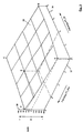
- FIG. 3 is a predetermined map 35, which shows the dependence between the Driver type setpoint FT_Soll, the driver type actual value FT_Ist and the increment INKR, and to determine the Increment INKR is used in the processing function S9.
- the driver type actual value FT_Ist is on a first Axis 36, the driver type setpoint FT_Soll on a second Axis 37 and the increment INKR on a third axis 38 applied.
- the map 35 there is a surface with the Endpoints A, B, C and D.
- the Driver type setpoint FT_Soll_n entered and the driver type actual value FT_Is determined. From the intersection of this The two values in the map 35 result in the associated one Increment increment on axis 38.
- FIG. 3 shows two examples for determining a Increments can be seen, the first example by dashed lines and the second example by dash-dotted lines Lines is shown.
- the distinctive function S10 becomes a counter shown in Fig. 4 39 with counter values ZW, which are defined in a certain Counter value ranges assigned to driver type or start-up style For example, are divided.
- the counter 39 has an up counter 40 and a down counter 41, which are symbolic as parallel number lines are shown.
- the increment counter 40 starts with the value zero and increases continuously up to one Counter value ZW of n, and that in the opposite direction current down counter 41 begins with the counter value of n and rises continuously up to the counter value zero.
- the intervals between the counter values ZW are at the Up counter 40 and down counter 41 are identical, so that the counter values of the up counter 40 and the down counter 41 cover.
- the counter values are in n-counter value ranges divided, the intervals of a counter value range ZB_auf at the high counter 40 and that of a counter value range For example, coincide with the down counter 41.
- the counter value ranges ZB_auf and ZB_ab are to each other by a certain number of counter values ZW, in the example according to FIG. 4 by ten counter values, transferred.
- the first counter value range ZB on 1 of the increment counter 40 begins with the counter reading zero according to FIG. 4 and ends at the counter value 50.
- the second counter value range ZB_auf_2 of the up counter 40 begins at the counter value 50 and ends at the counter value 80. In contrast, begins in the counter value range ZB_ab_1 in the present example of the down counter 41 with the counter value 40 and ends at the counter reading zero.
- the second counter value range ZB_ab_2 of the down counter 41 starts at the counter value 70 and ends with the counter value 40.
- the counter value ranges ZB_auf, ZB_ab represent sportiness levels of a driver type or Driving behavior, with an increasing number of the counter value range ZB_auf or ZB_ab the sportiness of the Movement of a vehicle is estimated to be higher.
- the width of an overlap zone 42 corresponds to the counter value interval by which the counter value ranges are offset from one another, i.e. the Overlap zone 42 in the example of FIG. 4 has a width of ten counter values.
- the overlap zones 42 represent calming zones.
- a counter value for this is shown in FIG. 4 as an example ZW_Range center of the counter value range ZB_auf_1 or ZB_ab_1 is drawn in, the counter value of which is 25.
- the discrimination function S10 outputs the result, that the increment is greater or less than zero, i.e. that is the driver type setpoint FT_Soll and driver type actual value FT_Ist differ from each other is in a processing function S12 a summand from a previous counter value ZW_Alt and the increment INKR as the new counter value ZW_Neu determined and the counter 39 set accordingly.
- the increment value 50 i.e. H. the counter value is increased by the Amount 50 increased.
- the counter 39 is thus dependent on the driving situation incremented or decremented directly without filtering or if the driver type actual value FT_actual and driver type setpoint match FT_Soll to the middle of a counter value range set.
- a switching characteristic SL from the new counter value ZW_Neu a variety of switching characteristics, each for one certain driver type or starting style are suitable.
Landscapes
- Engineering & Computer Science (AREA)
- General Engineering & Computer Science (AREA)
- Mechanical Engineering (AREA)
- Control Of Transmission Device (AREA)
Abstract
Claims (8)
- Procédé d'évaluation d'un processus de démarrage d'une boíte automatique d'un véhicule au moyen d'un appareil de commande électronique de la boíte, d'une unité de calcul, d'un micro-contrôleur, d'une unité de mémoire et d'une installation de commande pour activer un appareil de commande hydraulique de la boíte, caractérisé en ce qu' il comporte les phases suivants :1. on fournit à l'appareil de commande électronique (11) de la boíte un signal correspondant à un couple d'un moteur (M_M) et un signal correspondant à une vitesse de rotation du moteur (n_M) issus d'un appareil de commande (27) d'un moteur, et un signal correspondant à un couple (M_T) ou d'une vitesse de rotation (n_T) de l'arbre de turbine (18) issus d'une installation de mesure (24) d'un arbre de turbine (18) d'un convertisseur (2) de la boíte automatique (1),2. l'appareil de mesure électronique (11) fournit une valeur maximale (Max) de la différence dépendant du temps (DIFF(t)) entre le couple du moteur (M_M) et le couple (M_T) de l'arbre de turbine (18) ou de la différence (DIFF(t)) entre la vitesse de rotation (n_M) du moteur et la vitesse de rotation (n_T) de l'arbre de turbine (18),3. on détermine, à partir de la valeur maximale (Max) des différences (DIFF(t)), une courbe de commande caractéristique (SL) d'un mode de démarrage déterminé par comparaison d'une valeur de consigne (FT_Soll_n) d'un type de conducteur attribué à la valeur maximale (Max) avec la valeur effective (FT_Ist) d'un type de conducteur, et on règle un compteur (39) pour générer des signaux de commande transmis à l'appareil de commande hydraulique de la boíte (10).
- Procédé selon la revendication 1, caractérisé en ce que la valeur maximale (Max) des différences dépendant du temps (DIFF(t)) est déterminée de telle manière que :1. un première fonction différentielle (S1) est mise en oeuvre pour déterminer si une vitesse de rotation (n_AB) de sortie de la boíte d'un arbre de sortie de la boíte (22) est supérieur à une première valeur limite (GW1 ) prédéterminée,2. au cas où la vitesse de rotation (n_AB) de sortie de la boíte est inférieure ou égale à la première valeur limite (GW1), une fonction de traitement (S4) pour le retour dans un programme principal est activé, et,
si la vitesse de rotation (n_AB) de sortie de la boíte est supérieure à la première valeur limite (GW1 ) une fonction de calcul (S2) pour le calcul des différences (DIFF(t)) est démarrée,3. une autre fonction différentielle (S3) pour déterminer si la vitesse de rotation (n_AB) de l'arbre de sortie de la boíte (22) est supérieure à une deuxième valeur limite (GW2) est activée,4. au cas où la vitesse de rotation (n_AB) de la sortie de la boíte est supérieure ou égale à la deuxième valeur limite (GW2), la fonction de traitement (S4) est activée, pour le retour dans le programme principal, et si la vitesse de rotation (n_AB) de la sortie de la boíte est inférieure à la deuxième valeur limite (GW2), une fonction différentielle (S5) est activée pour déterminer si une différence (DIFF(t-n)) calculée est supérieure à une première valeur prédéterminée (GW1_DIFF) de la différence,5. lors du constat que la différence (DIFF(t_n)) est supérieure à la première valeur limite de la différence (GW1_DIFF), une autre fonction différentielle (S6) est lancée pour déterminer si la différence (DIFF(t_n)) est la valeur maximale (Max) et
si la différence (DIFF(t_n)) est inférieure ou égale à la première valeur limite de la différence (GW1_DIFF), la fonction de traitement (S4) pour le retour dans le programme principal est activée,6. une fonction d'attente (S7) est activée aussi longtemps que la fonction différentielle (S6) reconnaít une différence (DIFF(t_n)) comme valeur maximale (Max). - Procédé selon la revendication 1 ou 2, caractérisé en ce que la courbe de commande caractéristique (SL) est déterminée à partir de la valeur maximale (Max) de telle manière que,1. une fonction de traitement (S8) attribue à la valeur maximale (Max) la valeur de consigne du type de conducteur (FT_Soll_n) à partir de plusieurs valeurs de consigne de types de conducteurs (FT_Soll),2. la valeur de consigne du type de conducteur (FT_Soll_n) déterminée par la fonction de traitement (S8) est transmise à une autre fonction de traitement (S9), cette dernière étant agencée pour définir un incrément (INKR) entre la valeur de consigne du type de conducteur (FT_Soll_n) et une valeur effective (FT_Ist) du type de conducteur,3. l'incrément (INKR) est transmis à une fonction différentielle (S10) pour déterminer si l'incrément (INKR) est égal à une valeur nulle,4. dans l'affirmative, le compteur (39) avec des valeurs de compteur (ZW), qui sont réparties en secteurs de valeurs du compteur (ZB_auf, ZB_ab) correspondant à des comportements, respectivement des styles de conduite déterminés, est réglé de telle manière que la nouvelle valeur de compteur (ZW_Neu) est définie par la fonction ZW_Neu = ZW_Alt +/- ZW_Null dans une fonction de traitement (S11), et
au cas où l'incrément (INKR) est supérieur ou inférieur à zéro, une somme d'une valeur de compteur antérieure (ZW_Alt) et de l'incrément (INKR) est définie comme nouvelle valeur de compteur (ZW_Neu) dans une fonction de traitement (S12),5. une autre fonction différentielle (S13) est démarrée pour déterminer si la différence (DIFF(t_n)) est inférieure à une deuxième valeur limite (GW2_DIFF),6. dans l'affirmative, la nouvelle valeur de compteur (ZW_Neu) est attribuée à une courbe de commande caractéristique (SL) dans une fonction (S14), et une fonction de traitement (S15) est démarrée pour le retour dans le programme principal et, au cas où la différence (DIFF(t)) est supérieure ou égale à une deuxième valeur limite (GW2_DIFF), la fonction différentielle (S5) est à nouveau démarrée. - Procédé selon la revendication 3, caractérisé en ce que la fonction de traitement (S8) attribue une courbe caractéristique (43) à la valeur maximale (Max), cette courbe étant liée à la valeur de consigne (FT_Soll_n) du type de conducteur, par les différences (DIFF(t)) entre les valeurs de consigne (FT_Soll) des types de conducteurs.
- Procédé selon la revendication 3, caractérisé en ce que l'incrément (INKR) de la fonction de traitement (S9) est déterminée à partir d'un secteur caractéristique prédéterminé (35) qui détermine la dépendance entre la valeur de consigne du type de conducteur (FT_Soll), la valeur effective du type de conducteur (FT_Ist) et l'incrément (INKR).
- Procédé selon la revendication 3, caractérisé en ce que les données de valeurs du compteur (39) (ZB_auf, ZB_ab) présentent des zones de recouvrement (42) dans leurs zones limites.
- Procédé selon l'une quelconque des revendications 1 à 6, caractérisé en ce que le couple moteur (M_M) est calculé à partir de la vitesse de rotation (n_M) du moteur et d'un temps d'injection (t_ein) par l'unité de calcul (30) de l'appareil électronique de commande de la boíte (11).
- Procédé selon la revendication 1 à 7, caractérisé en ce que le couple (M_T) de l'arbre de turbine (18) est calculé à partir du couple moteur (M_M) et d'une conversion de démarrage du convertisseur hydrodynamique (2).
Applications Claiming Priority (3)
| Application Number | Priority Date | Filing Date | Title |
|---|---|---|---|
| DE19618811A DE19618811A1 (de) | 1996-05-10 | 1996-05-10 | Verfahren zur Bewertung eines Anfahrvorganges bei einem Automatgetriebe |
| DE19618811 | 1996-05-10 | ||
| PCT/EP1997/002319 WO1997043569A1 (fr) | 1996-05-10 | 1997-05-07 | Procede d'evaluation d'une phase de demarrage dans une boite automatique |
Publications (2)
| Publication Number | Publication Date |
|---|---|
| EP0897498A1 EP0897498A1 (fr) | 1999-02-24 |
| EP0897498B1 true EP0897498B1 (fr) | 2000-03-29 |
Family
ID=7793917
Family Applications (1)
| Application Number | Title | Priority Date | Filing Date |
|---|---|---|---|
| EP97923852A Expired - Lifetime EP0897498B1 (fr) | 1996-05-10 | 1997-05-07 | Procede d'evaluation d'une phase de demarrage dans une boite automatique |
Country Status (5)
| Country | Link |
|---|---|
| US (1) | US6205388B1 (fr) |
| EP (1) | EP0897498B1 (fr) |
| JP (1) | JP3986560B2 (fr) |
| DE (2) | DE19618811A1 (fr) |
| WO (1) | WO1997043569A1 (fr) |
Families Citing this family (5)
| Publication number | Priority date | Publication date | Assignee | Title |
|---|---|---|---|---|
| AT3030U1 (de) | 1998-09-01 | 1999-08-25 | Avl List Gmbh | Verfahren zur analyse und zur beeinflussung des fahrverhaltens von kraftfahrzeugen |
| DE10024847A1 (de) * | 2000-05-19 | 2001-11-22 | Zf Batavia Llc | Verfahren zur Anpassung des Momentenaufbaus eines Antriebsmotors an die Dynamik eines durch ihn angetriebenen Automatgetriebes |
| US6827668B2 (en) * | 2000-12-30 | 2004-12-07 | Robert Bosch Gmbh | Engine control system |
| US8565985B2 (en) * | 2007-10-22 | 2013-10-22 | Komatsu Ltd. | Transmission control device and method for working vehicle |
| CN108072342B (zh) * | 2017-11-23 | 2020-06-09 | 无锡合壮智慧交通有限公司 | 一种手动挡机动车档位的自动检测方法及装置 |
Family Cites Families (13)
| Publication number | Priority date | Publication date | Assignee | Title |
|---|---|---|---|---|
| JPH07107421B2 (ja) * | 1988-07-06 | 1995-11-15 | 日産自動車株式会社 | 車両の変速制御装置 |
| JP2701429B2 (ja) * | 1989-03-03 | 1998-01-21 | 三菱電機株式会社 | 自動変速機の制御装置 |
| DE3922051A1 (de) * | 1989-07-05 | 1991-01-24 | Porsche Ag | Verfahren und vorrichtung zur steuerung eines selbsttaetig schaltenden getriebes |
| EP0513424B1 (fr) * | 1991-05-17 | 1995-10-25 | Siemens Aktiengesellschaft | Transmission d'un automobile avec un dispositif de commande |
| US5251512A (en) * | 1991-10-15 | 1993-10-12 | General Motors Corporation | Dynamic shift control for an automatic transmission |
| DE4136613C2 (de) * | 1991-11-07 | 1994-03-10 | Bayerische Motoren Werke Ag | Gangwechselsteuerung in Kraftfahrzeugen |
| US5510982A (en) * | 1991-12-03 | 1996-04-23 | Hitachi, Ltd. | Automatic automobile transmission with variable shift pattern controlled in response to estimated running load |
| DE4312717A1 (de) * | 1993-04-20 | 1993-11-04 | Zahnradfabrik Friedrichshafen | Verfahren zur steuerung eines automatischen schaltgetriebes |
| DE4324091C2 (de) * | 1993-07-17 | 1998-11-26 | Porsche Ag | Verfahren und Vorrichtung zum Steuern eines automatischen Getriebes |
| JP3321292B2 (ja) * | 1994-05-18 | 2002-09-03 | ジヤトコ株式会社 | 自動変速機の変速制御装置 |
| US5612874A (en) * | 1994-10-14 | 1997-03-18 | Ford Motor Company | Multiple ratio automatic transmission with solenoid operated valves for effecting pressure buildup |
| US5646842A (en) | 1994-10-14 | 1997-07-08 | Ford Motor Company | Shift control system for a multiple ratio automatic transmission |
| JP3374167B2 (ja) * | 1994-12-01 | 2003-02-04 | ジヤトコ株式会社 | 自動変速機の学習制御装置 |
-
1996
- 1996-05-10 DE DE19618811A patent/DE19618811A1/de not_active Withdrawn
-
1997
- 1997-05-07 WO PCT/EP1997/002319 patent/WO1997043569A1/fr not_active Ceased
- 1997-05-07 US US09/171,895 patent/US6205388B1/en not_active Expired - Lifetime
- 1997-05-07 DE DE59701367T patent/DE59701367D1/de not_active Expired - Lifetime
- 1997-05-07 EP EP97923852A patent/EP0897498B1/fr not_active Expired - Lifetime
- 1997-05-07 JP JP54047597A patent/JP3986560B2/ja not_active Expired - Lifetime
Also Published As
| Publication number | Publication date |
|---|---|
| US6205388B1 (en) | 2001-03-20 |
| EP0897498A1 (fr) | 1999-02-24 |
| JP2000510559A (ja) | 2000-08-15 |
| JP3986560B2 (ja) | 2007-10-03 |
| DE59701367D1 (de) | 2000-05-04 |
| WO1997043569A1 (fr) | 1997-11-20 |
| DE19618811A1 (de) | 1997-11-13 |
Similar Documents
| Publication | Publication Date | Title |
|---|---|---|
| DE3341652C2 (fr) | ||
| DE3922051C2 (fr) | ||
| DE69300958T2 (de) | Fuzzy-Logik Schaltplanung für automatisches Getriebe. | |
| EP0589910B1 (fr) | Procede pour la commande d'une boite de vitesse automatique d'un vehicule automobile | |
| EP1199498B1 (fr) | Dispositif de commande pour transmission d'un véhicule automobile | |
| EP0870134B1 (fr) | Procede pour predeterminer le rapport de demultiplication d'une transmission a variation continue | |
| DE4040780C2 (de) | Vorrichtung zum Steuern eines automatischen Stufengetriebes | |
| DE69121013T2 (de) | System und Verfahren zur Regelung eines automatischen Getriebes | |
| DE69126263T2 (de) | Antriebseinheit | |
| EP0634591A2 (fr) | Méthode et dispositif de commande d'une boîte de vitesses automatique | |
| EP0897498B1 (fr) | Procede d'evaluation d'une phase de demarrage dans une boite automatique | |
| EP0897496B1 (fr) | Procede d'evaluation de la negociation d'une courbe pour une boite automatique | |
| EP1348086A1 (fr) | Systeme de commande de boite de vitesses | |
| DE4342204A1 (de) | Verfahren zur Steuerung der Antriebseinheit von Kraftfahrzeugen | |
| DE4136613A1 (de) | Gangwechselsteuerung in kraftfahrzeugen | |
| EP0897497B1 (fr) | Procede d'evaluation d'un trace de route pour une boite automatique | |
| EP1749161B1 (fr) | Procede de commande d'une boite de vitesses | |
| EP1021667B1 (fr) | Procede d'adaptation d'un embrayage de pontage de convertisseur | |
| DE19526728A1 (de) | Steuerungssystem für Automatikgetriebe | |
| DE19921937A1 (de) | Verfahren zur Steuerung des Gangwechsels in einem Automatikgetriebe | |
| DE102008038095A1 (de) | Steuervorrichtung | |
| EP0760066B1 (fr) | Procede de commande d'une boite de vitesses automatique | |
| DE4326330B4 (de) | Vorrichtung in Kraftfahrzeugen mit einem mehrere Schalterstellungen aufweisenden Progammwahlschalter zur manuellen Anwahl eines Schaltprogrammes | |
| DE4293772C2 (de) | Gangwechselsteuerung für ein Fahrzeugautomatikgetriebe | |
| DE19641762A1 (de) | Steuerungsvorrichtung mit neuronalem Netzwerk für ein automatisches Stufenwechselgetriebe |
Legal Events
| Date | Code | Title | Description |
|---|---|---|---|
| PUAI | Public reference made under article 153(3) epc to a published international application that has entered the european phase |
Free format text: ORIGINAL CODE: 0009012 |
|
| 17P | Request for examination filed |
Effective date: 19980916 |
|
| AK | Designated contracting states |
Kind code of ref document: A1 Designated state(s): DE FR GB |
|
| GRAG | Despatch of communication of intention to grant |
Free format text: ORIGINAL CODE: EPIDOS AGRA |
|
| 17Q | First examination report despatched |
Effective date: 19990809 |
|
| GRAG | Despatch of communication of intention to grant |
Free format text: ORIGINAL CODE: EPIDOS AGRA |
|
| GRAH | Despatch of communication of intention to grant a patent |
Free format text: ORIGINAL CODE: EPIDOS IGRA |
|
| GRAH | Despatch of communication of intention to grant a patent |
Free format text: ORIGINAL CODE: EPIDOS IGRA |
|
| GRAA | (expected) grant |
Free format text: ORIGINAL CODE: 0009210 |
|
| AK | Designated contracting states |
Kind code of ref document: B1 Designated state(s): DE FR GB |
|
| GBT | Gb: translation of ep patent filed (gb section 77(6)(a)/1977) |
Effective date: 20000411 |
|
| REF | Corresponds to: |
Ref document number: 59701367 Country of ref document: DE Date of ref document: 20000504 |
|
| ET | Fr: translation filed | ||
| PLBE | No opposition filed within time limit |
Free format text: ORIGINAL CODE: 0009261 |
|
| STAA | Information on the status of an ep patent application or granted ep patent |
Free format text: STATUS: NO OPPOSITION FILED WITHIN TIME LIMIT |
|
| 26N | No opposition filed | ||
| REG | Reference to a national code |
Ref country code: GB Ref legal event code: IF02 |
|
| REG | Reference to a national code |
Ref country code: FR Ref legal event code: PLFP Year of fee payment: 20 |
|
| PGFP | Annual fee paid to national office [announced via postgrant information from national office to epo] |
Ref country code: DE Payment date: 20160504 Year of fee payment: 20 Ref country code: GB Payment date: 20160504 Year of fee payment: 20 |
|
| PGFP | Annual fee paid to national office [announced via postgrant information from national office to epo] |
Ref country code: FR Payment date: 20160412 Year of fee payment: 20 |
|
| REG | Reference to a national code |
Ref country code: DE Ref legal event code: R071 Ref document number: 59701367 Country of ref document: DE |
|
| REG | Reference to a national code |
Ref country code: GB Ref legal event code: PE20 Expiry date: 20170506 |
|
| PG25 | Lapsed in a contracting state [announced via postgrant information from national office to epo] |
Ref country code: GB Free format text: LAPSE BECAUSE OF EXPIRATION OF PROTECTION Effective date: 20170506 |