EP0897496B1 - Procede d'evaluation de la negociation d'une courbe pour une boite automatique - Google Patents
Procede d'evaluation de la negociation d'une courbe pour une boite automatique Download PDFInfo
- Publication number
- EP0897496B1 EP0897496B1 EP97921856A EP97921856A EP0897496B1 EP 0897496 B1 EP0897496 B1 EP 0897496B1 EP 97921856 A EP97921856 A EP 97921856A EP 97921856 A EP97921856 A EP 97921856A EP 0897496 B1 EP0897496 B1 EP 0897496B1
- Authority
- EP
- European Patent Office
- Prior art keywords
- increment
- inkr
- driver
- vehicle
- determined
- Prior art date
- Legal status (The legal status is an assumption and is not a legal conclusion. Google has not performed a legal analysis and makes no representation as to the accuracy of the status listed.)
- Expired - Lifetime
Links
- 238000000034 method Methods 0.000 title claims abstract description 17
- 230000001133 acceleration Effects 0.000 claims abstract description 11
- 238000013507 mapping Methods 0.000 claims 1
- 230000005540 biological transmission Effects 0.000 description 30
- 238000002485 combustion reaction Methods 0.000 description 4
- 238000010586 diagram Methods 0.000 description 2
- 230000000694 effects Effects 0.000 description 2
- 238000011156 evaluation Methods 0.000 description 2
- 230000001914 calming effect Effects 0.000 description 1
- 230000008878 coupling Effects 0.000 description 1
- 238000010168 coupling process Methods 0.000 description 1
- 238000005859 coupling reaction Methods 0.000 description 1
- 230000001419 dependent effect Effects 0.000 description 1
- 230000004069 differentiation Effects 0.000 description 1
- 238000001914 filtration Methods 0.000 description 1
- 239000012530 fluid Substances 0.000 description 1
Images


Classifications
-
- F—MECHANICAL ENGINEERING; LIGHTING; HEATING; WEAPONS; BLASTING
- F16—ENGINEERING ELEMENTS AND UNITS; GENERAL MEASURES FOR PRODUCING AND MAINTAINING EFFECTIVE FUNCTIONING OF MACHINES OR INSTALLATIONS; THERMAL INSULATION IN GENERAL
- F16H—GEARING
- F16H61/00—Control functions within control units of change-speed- or reversing-gearings for conveying rotary motion ; Control of exclusively fluid gearing, friction gearing, gearings with endless flexible members or other particular types of gearing
- F16H61/02—Control functions within control units of change-speed- or reversing-gearings for conveying rotary motion ; Control of exclusively fluid gearing, friction gearing, gearings with endless flexible members or other particular types of gearing characterised by the signals used
- F16H61/0202—Control functions within control units of change-speed- or reversing-gearings for conveying rotary motion ; Control of exclusively fluid gearing, friction gearing, gearings with endless flexible members or other particular types of gearing characterised by the signals used the signals being electric
- F16H61/0204—Control functions within control units of change-speed- or reversing-gearings for conveying rotary motion ; Control of exclusively fluid gearing, friction gearing, gearings with endless flexible members or other particular types of gearing characterised by the signals used the signals being electric for gearshift control, e.g. control functions for performing shifting or generation of shift signal
- F16H61/0213—Control functions within control units of change-speed- or reversing-gearings for conveying rotary motion ; Control of exclusively fluid gearing, friction gearing, gearings with endless flexible members or other particular types of gearing characterised by the signals used the signals being electric for gearshift control, e.g. control functions for performing shifting or generation of shift signal characterised by the method for generating shift signals
-
- F—MECHANICAL ENGINEERING; LIGHTING; HEATING; WEAPONS; BLASTING
- F16—ENGINEERING ELEMENTS AND UNITS; GENERAL MEASURES FOR PRODUCING AND MAINTAINING EFFECTIVE FUNCTIONING OF MACHINES OR INSTALLATIONS; THERMAL INSULATION IN GENERAL
- F16H—GEARING
- F16H59/00—Control inputs to control units of change-speed- or reversing-gearings for conveying rotary motion
- F16H2059/003—Detecting or using driving style of a driver, e.g. for adapting shift schedules
-
- F—MECHANICAL ENGINEERING; LIGHTING; HEATING; WEAPONS; BLASTING
- F16—ENGINEERING ELEMENTS AND UNITS; GENERAL MEASURES FOR PRODUCING AND MAINTAINING EFFECTIVE FUNCTIONING OF MACHINES OR INSTALLATIONS; THERMAL INSULATION IN GENERAL
- F16H—GEARING
- F16H61/00—Control functions within control units of change-speed- or reversing-gearings for conveying rotary motion ; Control of exclusively fluid gearing, friction gearing, gearings with endless flexible members or other particular types of gearing
- F16H61/02—Control functions within control units of change-speed- or reversing-gearings for conveying rotary motion ; Control of exclusively fluid gearing, friction gearing, gearings with endless flexible members or other particular types of gearing characterised by the signals used
- F16H61/0202—Control functions within control units of change-speed- or reversing-gearings for conveying rotary motion ; Control of exclusively fluid gearing, friction gearing, gearings with endless flexible members or other particular types of gearing characterised by the signals used the signals being electric
- F16H61/0204—Control functions within control units of change-speed- or reversing-gearings for conveying rotary motion ; Control of exclusively fluid gearing, friction gearing, gearings with endless flexible members or other particular types of gearing characterised by the signals used the signals being electric for gearshift control, e.g. control functions for performing shifting or generation of shift signal
- F16H61/0213—Control functions within control units of change-speed- or reversing-gearings for conveying rotary motion ; Control of exclusively fluid gearing, friction gearing, gearings with endless flexible members or other particular types of gearing characterised by the signals used the signals being electric for gearshift control, e.g. control functions for performing shifting or generation of shift signal characterised by the method for generating shift signals
- F16H2061/0227—Shift map selection, i.e. methods for controlling selection between different shift maps, e.g. to initiate switch to a map for up-hill driving
-
- F—MECHANICAL ENGINEERING; LIGHTING; HEATING; WEAPONS; BLASTING
- F16—ENGINEERING ELEMENTS AND UNITS; GENERAL MEASURES FOR PRODUCING AND MAINTAINING EFFECTIVE FUNCTIONING OF MACHINES OR INSTALLATIONS; THERMAL INSULATION IN GENERAL
- F16H—GEARING
- F16H59/00—Control inputs to control units of change-speed- or reversing-gearings for conveying rotary motion
- F16H59/50—Inputs being a function of the status of the machine, e.g. position of doors or safety belts
- F16H59/58—Inputs being a function of the status of the machine, e.g. position of doors or safety belts dependent on signals from the steering
Definitions
- the invention relates to a method for evaluation cornering in the automatic transmission of a vehicle by means of an electronic transmission control unit a calculation unit, a micro controller, one Storage device and a control device for Control of a hydraulic transmission control unit.
- Such an intelligent switching program is, for example described in DE-OS 39 22 051, wherein under "Intelligent" means that the driver of a vehicle no dial to set a specific one Switching range, such as B. for sporty driving or economical Drive, must operate, since an electronic transmission control unit based on input variables on the behavior of the driver and thus the driver type.
- input variables serve here, for example, the signal Throttle valve, the speed of an internal combustion engine and the longitudinal and lateral acceleration determined from the wheel speeds.
- the input variables determines a driving activity or a driver type. Based on the driver type, a corresponding Shifting characteristic curve from a plurality of shifting characteristic curves selected. For example, for a quiet driver type a switching line with low switching points and for a sporty driver type a shift characteristic with high Switching points selected.
- a driver's driving behavior in different Driving situations may be different, e.g. B. a otherwise a sporty driver, but one in corners slower driving preferred, a general classification of his driving behavior as sporty in this driving situation feel annoying.
- the circuit program must therefore be flexible can react to different driving situations.
- a method is related a cornering known in which an upshift only is then permitted when the lateral acceleration is below of a limit.
- This method known from the prior art thus has the disadvantage that when cornering with a high lateral acceleration prevents a circuit but the driving activity or driver type is not evaluated.
- the method according to the invention has the advantage that it is simple even when cornering enables the evaluation of a driver type.
- the method according to the invention It is advantageous that the driver type actual value used in the method always kept up to date becomes.
- the Automatic transmission 1 is a highly schematic System diagram of an automatic transmission 1 shown.
- the Automatic transmission 1 consists of a mechanical part 1A with a hydrodynamic converter 2 and as couplings or brakes trained switching elements 3 to 9 and a control part 1B with a hydraulic control unit 10 and an electronic control unit 11.
- the automatic transmission 1 is driven by a drive unit 12, which is expediently designed as an internal combustion engine, driven via a drive shaft 13.
- the drive shaft 13 is with a pump wheel 14 of the hydrodynamic Converter 2, which is also a turbine 15 and a Stator 16, rotatably connected.
- a converter clutch 17 is arranged in parallel to that hydrodynamic converter 2, a converter clutch 17 is arranged.
- the converter clutch 17 and the turbine wheel 15 lead to a turbine shaft 18, the turbine shaft 18 the same when the converter clutch 17 is actuated Speed as the drive shaft 13 has.
- the automatic transmission 1 has a transmission output shaft as the output 22 formed, which on a not shown Differential leads that over two axle half-waves - Also not shown - drive wheels of a vehicle drives. The selection of a gear level is made via a corresponding clutch / brake combination. Since the described elements of the automatic transmission 1 for the further Understanding of the invention is of no further importance are not dealt with in more detail at this point.
- the Storage device 29 which expediently as an EProm, EEProm or executed as buffered RAM, the gear relevant Data, for example programs and count data and diagnostic data.
- the control device 31 is used to control itself in the hydraulic control unit 10 located actuators 32, which are used to pressurize the clutches or brakes 3 to 9 are provided, as symbolic by the arrows 33 is indicated in Fig. 1.
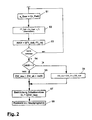
- FIG. 2 is a program flow chart for a subroutine for evaluating cornering.
- a measuring device 34 determined wheel speed n_Rad to a first processing function S1 of the calculation unit 30 for determining a Driver types issued.
- the processing function S1 delivers by a calculation from the wheel speeds n_rad Lateral acceleration a_Cross the vehicle.
- the thus determined Lateral acceleration a_Quer is used by the processing function S1 forwarded to a processing function S2, in the from the vehicle lateral acceleration a_Quer and a vehicle speed v_F a driver type setpoint FT_Soll is determined.
- the vehicle speed v_F becomes from one on the drive shaft 22 of the automatic transmission 1 measured transmission output speed n_AB from the Calculation unit 30 determined.
- Processing function S3 is compared by a comparison of the Driver type setpoint FT_Soll with an actual driver type value FT_Is an increment INKR determined.
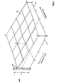
- the 3 is a predetermined map 35, which shows the dependence between the Driver type setpoint FT_Soll, the driver type actual value FT_Ist and the increment INKR, and to determine the Incremental INKR is used in the processing function S3.
- the driver type actual value FT_Ist is on a first Axis 36, the driver type setpoint FT_Soll on a second Axis 37 and the increment INKR on a third axis 38 applied.
- the map 35 there is a surface with the Endpoints A, B, C and D.
- the Driver type setpoint FT_Soll and the driver type actual value FT_Ist certainly. From the intersection of these two values in the Map 35 gives the associated increment INKR the axis 38.
- FIG. 3 shows two examples for determining a Increments can be seen, the first example by dashed lines and the second example by dash-dotted lines Lines is shown.
- the distinctive function S4 delivers, becomes a counter shown in Fig. 4 39 with counter values ZW, which are defined in a certain Counter value ranges assigned to driver type or cornering style For example, are divided.
- the counter 39 has an up counter 40 and a down counter 41, which are symbolic as parallel number lines are shown.
- the increment counter 40 starts with the value zero and increases continuously up to one Counter value ZW of n, and that in the opposite direction current down counter 41 begins with the counter value of n and rises continuously up to the counter value zero.
- the intervals between the counter values ZW are at the Up counter 40 and down counter 41 are identical, so that the counter values of the up counter 40 and the down counter 41 cover.
- the counter values are in n-counter value ranges divided, the intervals of a counter value range ZB_etz at the high counter 40 and that of a counter value range For example, coincide with the down counter 41.
- the counter value ranges ZB_auf and ZB_ab are to each other by a certain number of counter values ZW, in the example according to FIG. 4 by ten counter values, transferred.
- the first counter value range ZB_auf_1 of the incremental counter 40 begins with the counter reading zero according to FIG. 4 and ends at the counter value 50.
- the second counter value range ZB_auf_2 of the up counter 40 begins at the counter value 50 and ends at the counter value 80.
- the second counter value range ZB_ab_2 of the down counter 41 starts at the counter value 70 and ends with the counter value 40.
- the counter value ranges ZB_auf, ZB_ab represent sportiness levels of a driver type or Driving behavior, with an increasing number of the counter value range ZB_auf or ZB_ab the sportiness of the Movement of a vehicle is estimated to be higher.
- Between two correlating counter value ranges ZB_auf_n and ZB_ab_n result in overlap zones in the border areas 42 due to the offset of the counter value ranges ZB_auf and ZB_ab to each other.
- the width of an overlap zone 42 corresponds to the counter value interval by which the counter value ranges are offset from one another, d. H.
- the Overlap zone 42 in the example of FIG. 4 has a width of ten counter values.
- the overlap zones 42 represent calming zones.
- FIG. 4 An example of this in FIG. 4 is a counter value ZW_range center of the counter value range ZB_auf_1 or ZB_ab_1 is drawn in, the counter value of which is 25.
- the distinction function S4 outputs the result, that the increment is greater or less than zero, i.e. that is the driver type setpoint FT_Soll and driver type actual value FT_Ist differ from each other is in a processing function S5 a summand from a previous counter value ZW_Alt and the increment INKR as the new counter value ZW_Neu determined and the counter 39 set accordingly.
- the increment value 40 i.e. H. the counter value is increased by the amount 40 increased.
- the new counter value ZW_Neu a switching characteristic SL from a variety of switching characteristics, each for a specific Driver type or cornering style are suitable.
- this function is only executed when the Has been negotiated, d. H. when the vehicle lateral acceleration is less than a limit (a_Quer ⁇ GW).
- the INKR increment is used to select one switching characteristic corresponding to the driver type with high or low switching points.
Landscapes
- Engineering & Computer Science (AREA)
- General Engineering & Computer Science (AREA)
- Mechanical Engineering (AREA)
- Control Of Transmission Device (AREA)
Abstract
Claims (5)
- Procédé d'évaluation de la négociation d'une courbe pour une boíte automatique d'un véhicule au moyen d'un appareil de commande électronique de la transmission comportant une unité de calcul, un micro-contrôleur, une mémoire et un dispositif de commande pour un appareil de commande hydraulique de la transmission, caractérisé par les étapes de procédé suivantes:1. à partir des vitesses de rotation (n-Rad) mesurées par un dispositif de mesure (34) sur les roues du véhicule, est déterminée, dans une première fonction de traitement (S1) de l'unité de calcul (30), une accélération transversale (a_Quer) du véhicule,2. dans une autre fonction de traitement (S2), une valeur de consigne du type de conducteur (FT_Soll) est déterminée à partir de l'accélération transversale du véhicule (a_Quer) et d'une vitesse du véhicule (v_F),3. à partir d'un incrément (INKR) entre la valeur de consigne du type de conducteur (FT_Soll) et une valeur effective du type de conducteur (FT_Ist) est déterminée une courbe caractéristique des changements de vitesse (SL) à partir de plusieurs courbes caractéristiques affectées à un type de conducteur défini, respectivement à un style de conduite dans les virages.
- Procédé selon la revendication 1, caractérisé en ce que la vitesse du véhicule (v_F) est déterminée par l'unité de calcul (30) dans la fonction de traitement (S2) à partir d'une vitesse de rotation de sortie de la boíte de vitesses (n_AB) mesurée sur un arbre de sortie (22) de la boíte.
- Procédé selon les revendications 1 ou 2, caractérisé en ce que l'incrément (INKR) est déterminé dans une fonction de traitement (S3) à partir d'un diagramme caractéristique prédéfini (35), lequel détermine la relation entre la valeur de consigne du type de conducteur (FT_Soll), la valeur réelle du type de conducteur (FT_Ist) et l'incrément (INKR).
- Procédé selon l'une des revendications 1 à 3, caractérisé en ce que pour déterminer la courbe caractéristique des changements de vitesse (SL) à partir de l'incrément (INKR) :1. l'incrément (INKR) est transmis à une fonction de discrimination (S4) en vue de vérifier si l'incrément (INKR) est égal à une valeur nulle et, si oui, un compteur (39) avec des valeurs de compteur (ZW) réparties dans des zones de valeurs de compteur définies affectées à un type de conducteur spécifique, respectivement à un style de conduite dans les virages (ZB_auf, ZB_ab), est réglé de telle façon qu'une nouvelle valeur de compteur (ZW_Neu) est déterminée selon la fonction ZW_Neu = ZW_Alt +/- ZW_Null dans une fonction de traitement (S11), et
si l'incrément (INKR) est supérieur ou inférieur à zéro, un opérande d'une somme est déterminé dans une fonction de traitement (S5) à partir d'une valeur de compteur précédant (ZW_Alt) et l'incrément (INKR) comme nouvelle valeur de compteur (ZW_Neu),2. dans une fonction de traitement (S7), une courbe caractéristique de changement de vitesse (SL) est affectée à la nouvelle valeur de compteur (ZW_Neu) et une fonction de traitement (S8) est démarrée pour le retour dans un programme principal. - Procédé selon la revendication 4, caractérisé en ce que les zones des valeurs de compteur (ZB_auf, ZB_ab) du compteur (39) présentent des intersections (42) dans leurs zones limites.
Applications Claiming Priority (3)
| Application Number | Priority Date | Filing Date | Title |
|---|---|---|---|
| DE19618805 | 1996-05-10 | ||
| DE19618805A DE19618805A1 (de) | 1996-05-10 | 1996-05-10 | Verfahren zur Bewertung einer Kurvenfahrt bei einem Automatgetriebe |
| PCT/EP1997/002318 WO1997043568A1 (fr) | 1996-05-10 | 1997-05-07 | Procede d'evaluation de la negociation d'une courbe pour une boite automatique |
Publications (2)
| Publication Number | Publication Date |
|---|---|
| EP0897496A1 EP0897496A1 (fr) | 1999-02-24 |
| EP0897496B1 true EP0897496B1 (fr) | 1999-12-29 |
Family
ID=7793911
Family Applications (1)
| Application Number | Title | Priority Date | Filing Date |
|---|---|---|---|
| EP97921856A Expired - Lifetime EP0897496B1 (fr) | 1996-05-10 | 1997-05-07 | Procede d'evaluation de la negociation d'une courbe pour une boite automatique |
Country Status (5)
| Country | Link |
|---|---|
| US (1) | US6259994B1 (fr) |
| EP (1) | EP0897496B1 (fr) |
| JP (1) | JP4079999B2 (fr) |
| DE (2) | DE19618805A1 (fr) |
| WO (1) | WO1997043568A1 (fr) |
Cited By (1)
| Publication number | Priority date | Publication date | Assignee | Title |
|---|---|---|---|---|
| WO2011098174A1 (fr) | 2010-02-12 | 2011-08-18 | Zf Friedrichshafen Ag | Procédé de détermination et de commande de la vitesse optimale avant l'abord d'une courbe pour un véhicule automobile comprenant une boîte de vitesses automatique |
Families Citing this family (6)
| Publication number | Priority date | Publication date | Assignee | Title |
|---|---|---|---|---|
| DE19839858A1 (de) | 1998-09-02 | 2000-03-09 | Zahnradfabrik Friedrichshafen | Verfahren zur Kurvenfahrterkennung für ein Fahrzeug mit selbsttätig schaltendem Getriebe |
| DE19911301A1 (de) | 1999-03-13 | 2000-09-14 | Zahnradfabrik Friedrichshafen | Verfahren zur Steuerung eines Automatgetriebes mit Ermittlung eines Querbeschleunigungswertes |
| KR20030085561A (ko) * | 2001-03-22 | 2003-11-05 | 룩라멜렌운트쿠플룽스바우베타일리궁스카게 | 차량의 자동 트랜스미션을 제어 및/또는 조정하기 위한 방법 |
| DE10163401A1 (de) * | 2001-12-21 | 2003-07-03 | Zf Sachs Ag | Kraftfahrzeug mit einem Mehrfachkupplungs-Mehrganggetriebe |
| US8880308B2 (en) * | 2011-12-12 | 2014-11-04 | Chrysler Group Llc | Methods and system for using vehicle longitudinal acceleration for transmission control |
| FR3013094B1 (fr) * | 2013-11-08 | 2015-11-27 | Renault Sas | Dispositif et procede de controle d'une transmision automatique en situation de virage |
Family Cites Families (13)
| Publication number | Priority date | Publication date | Assignee | Title |
|---|---|---|---|---|
| DE3341652A1 (de) * | 1983-11-18 | 1985-06-05 | Dr.Ing.H.C. F. Porsche Ag, 7000 Stuttgart | Verfahren und vorrichtung zur steuerung einer kupplungs-getriebe-einheit |
| US5099720A (en) * | 1987-02-26 | 1992-03-31 | Zahnradfabrik Friedrichshafen Ag | Control mechanism for an automatic gear-shifting transmission using turn signal control unit |
| DE3922040A1 (de) * | 1989-07-05 | 1991-01-17 | Porsche Ag | Verfahren und vorrichtung zur steuerung eines selbsttaetig schaltenden getriebes |
| DE3922051A1 (de) * | 1989-07-05 | 1991-01-24 | Porsche Ag | Verfahren und vorrichtung zur steuerung eines selbsttaetig schaltenden getriebes |
| EP0471102B1 (fr) * | 1990-08-14 | 1994-01-05 | Siemens Aktiengesellschaft | Commande de boîte de vitesses pour véhicule à moteur |
| JP2580865B2 (ja) * | 1990-10-17 | 1997-02-12 | 三菱自動車工業株式会社 | 車両用ステアリング制御装置 |
| JPH04272568A (ja) | 1991-02-25 | 1992-09-29 | Hitachi Ltd | 自動変速機制御装置 |
| DE4120603C2 (de) | 1991-06-21 | 1995-11-09 | Porsche Ag | Steuereinrichtung für ein selbsttätig schaltendes Getriebe eines Kraftfahrzeugs |
| JP2765341B2 (ja) * | 1992-02-14 | 1998-06-11 | 三菱自動車工業株式会社 | 車両用サスペンション装置 |
| DE4312717A1 (de) * | 1993-04-20 | 1993-11-04 | Zahnradfabrik Friedrichshafen | Verfahren zur steuerung eines automatischen schaltgetriebes |
| EP0638742A1 (fr) * | 1993-08-12 | 1995-02-15 | Siemens Aktiengesellschaft | Régulation d'un sous-système d'un véhicule, en particulier d'une transmission automatique |
| KR100335041B1 (ko) * | 1994-01-19 | 2002-10-09 | 지멘스 악티엔게젤샤프트 | 차량변속기용제어기 |
| DE19527412A1 (de) * | 1995-07-27 | 1997-01-30 | Zahnradfabrik Friedrichshafen | Vorrichtung zur Regelung des Übersetzungsverhältnisses eines stufenlosen Getriebes |
-
1996
- 1996-05-10 DE DE19618805A patent/DE19618805A1/de not_active Withdrawn
-
1997
- 1997-05-07 WO PCT/EP1997/002318 patent/WO1997043568A1/fr not_active Ceased
- 1997-05-07 EP EP97921856A patent/EP0897496B1/fr not_active Expired - Lifetime
- 1997-05-07 JP JP54047497A patent/JP4079999B2/ja not_active Expired - Lifetime
- 1997-05-07 DE DE59700939T patent/DE59700939D1/de not_active Expired - Lifetime
- 1997-05-07 US US09/180,313 patent/US6259994B1/en not_active Expired - Lifetime
Cited By (3)
| Publication number | Priority date | Publication date | Assignee | Title |
|---|---|---|---|---|
| WO2011098174A1 (fr) | 2010-02-12 | 2011-08-18 | Zf Friedrichshafen Ag | Procédé de détermination et de commande de la vitesse optimale avant l'abord d'une courbe pour un véhicule automobile comprenant une boîte de vitesses automatique |
| DE102010001873A1 (de) | 2010-02-12 | 2011-08-18 | ZF Friedrichshafen AG, 88046 | Verfahren zur Bestimmung und Schaltung des optimalen Ganges vor der Einfahrt in eine Kurve bei einem Kraftfahrzeug umfassend ein Automatgetriebe |
| US9043104B2 (en) | 2010-02-12 | 2015-05-26 | Zf Friedrichshafen Ag | Method for determining and selecting the optimal gear before driving into a curve for a motor vehicle having an automatic transmission |
Also Published As
| Publication number | Publication date |
|---|---|
| EP0897496A1 (fr) | 1999-02-24 |
| DE19618805A1 (de) | 1997-11-13 |
| US6259994B1 (en) | 2001-07-10 |
| JP2000510558A (ja) | 2000-08-15 |
| DE59700939D1 (de) | 2000-02-03 |
| JP4079999B2 (ja) | 2008-04-23 |
| WO1997043568A1 (fr) | 1997-11-20 |
Similar Documents
| Publication | Publication Date | Title |
|---|---|---|
| DE3341652C2 (fr) | ||
| DE3922051C2 (fr) | ||
| DE69300958T2 (de) | Fuzzy-Logik Schaltplanung für automatisches Getriebe. | |
| EP0589910B1 (fr) | Procede pour la commande d'une boite de vitesse automatique d'un vehicule automobile | |
| DE3402872C2 (fr) | ||
| EP1199498B1 (fr) | Dispositif de commande pour transmission d'un véhicule automobile | |
| DE3032403A1 (de) | Halbautomatische getriebesteuerung | |
| EP1030984B1 (fr) | Procede de commande d'une boite de vitesses automatique | |
| DE2755201A1 (de) | Verfahren zur elektronischen nachbildung eines freilaufes | |
| EP1880128B1 (fr) | Procede de commande d'une boite de vitesses dans un vehicule a moteur | |
| DE3939303C2 (de) | Schaltsteuereinrichtung für ein Automatikgetriebe für Kraftfahrzeuge | |
| EP0897496B1 (fr) | Procede d'evaluation de la negociation d'une courbe pour une boite automatique | |
| EP0764089B1 (fr) | Dispositif de commande pour un vehicule | |
| DE68913463T2 (de) | Automatisches Steuerungssystem für Getriebe. | |
| DE4337957C2 (de) | Schalteinrichtung für ein Getriebe | |
| EP1348086A1 (fr) | Systeme de commande de boite de vitesses | |
| EP0897497B1 (fr) | Procede d'evaluation d'un trace de route pour une boite automatique | |
| EP0897498B1 (fr) | Procede d'evaluation d'une phase de demarrage dans une boite automatique | |
| EP1749161B1 (fr) | Procede de commande d'une boite de vitesses | |
| EP1021667B1 (fr) | Procede d'adaptation d'un embrayage de pontage de convertisseur | |
| DE69623537T2 (de) | Verfahren und Vorrichtung zur Verhinderung von Gang-Rückschaltungen | |
| DE19732369B4 (de) | Verfahren zur Ansteuerung eines Automatikgetriebes und eine Schaltvorrichtung zur Auswahl der Fahrstrategien | |
| EP0760066B1 (fr) | Procede de commande d'une boite de vitesses automatique | |
| DE102007048862B4 (de) | Verfahren und Vorrichtung zur Begrenzung einer Drehzahl eines Motors | |
| DE102004027575B3 (de) | Verfahren zur Ansteuerung einer automatischen Kupplung |
Legal Events
| Date | Code | Title | Description |
|---|---|---|---|
| PUAI | Public reference made under article 153(3) epc to a published international application that has entered the european phase |
Free format text: ORIGINAL CODE: 0009012 |
|
| 17P | Request for examination filed |
Effective date: 19980916 |
|
| AK | Designated contracting states |
Kind code of ref document: A1 Designated state(s): DE FR GB |
|
| RIN1 | Information on inventor provided before grant (corrected) |
Inventor name: O'CONNOR, GARY Inventor name: POLJANSEK, MARKO Inventor name: SCHMID, WOLFGANG Inventor name: HENNEKEN, MARKUS |
|
| GRAG | Despatch of communication of intention to grant |
Free format text: ORIGINAL CODE: EPIDOS AGRA |
|
| GRAG | Despatch of communication of intention to grant |
Free format text: ORIGINAL CODE: EPIDOS AGRA |
|
| GRAH | Despatch of communication of intention to grant a patent |
Free format text: ORIGINAL CODE: EPIDOS IGRA |
|
| 17Q | First examination report despatched |
Effective date: 19990503 |
|
| GRAH | Despatch of communication of intention to grant a patent |
Free format text: ORIGINAL CODE: EPIDOS IGRA |
|
| GRAA | (expected) grant |
Free format text: ORIGINAL CODE: 0009210 |
|
| AK | Designated contracting states |
Kind code of ref document: B1 Designated state(s): DE FR GB |
|
| GBT | Gb: translation of ep patent filed (gb section 77(6)(a)/1977) |
Effective date: 19991229 |
|
| REF | Corresponds to: |
Ref document number: 59700939 Country of ref document: DE Date of ref document: 20000203 |
|
| ET | Fr: translation filed | ||
| PLBE | No opposition filed within time limit |
Free format text: ORIGINAL CODE: 0009261 |
|
| STAA | Information on the status of an ep patent application or granted ep patent |
Free format text: STATUS: NO OPPOSITION FILED WITHIN TIME LIMIT |
|
| 26N | No opposition filed | ||
| REG | Reference to a national code |
Ref country code: GB Ref legal event code: IF02 |
|
| REG | Reference to a national code |
Ref country code: FR Ref legal event code: PLFP Year of fee payment: 20 |
|
| PGFP | Annual fee paid to national office [announced via postgrant information from national office to epo] |
Ref country code: GB Payment date: 20160504 Year of fee payment: 20 Ref country code: DE Payment date: 20160504 Year of fee payment: 20 |
|
| PGFP | Annual fee paid to national office [announced via postgrant information from national office to epo] |
Ref country code: FR Payment date: 20160412 Year of fee payment: 20 |
|
| REG | Reference to a national code |
Ref country code: DE Ref legal event code: R071 Ref document number: 59700939 Country of ref document: DE |
|
| REG | Reference to a national code |
Ref country code: GB Ref legal event code: PE20 Expiry date: 20170506 |
|
| PG25 | Lapsed in a contracting state [announced via postgrant information from national office to epo] |
Ref country code: GB Free format text: LAPSE BECAUSE OF EXPIRATION OF PROTECTION Effective date: 20170506 |