EP0897645B1 - Rufweiterleitungsfunktion für eine tragbare funkkommunikationseinrichtung - Google Patents
Rufweiterleitungsfunktion für eine tragbare funkkommunikationseinrichtung Download PDFInfo
- Publication number
- EP0897645B1 EP0897645B1 EP97922276A EP97922276A EP0897645B1 EP 0897645 B1 EP0897645 B1 EP 0897645B1 EP 97922276 A EP97922276 A EP 97922276A EP 97922276 A EP97922276 A EP 97922276A EP 0897645 B1 EP0897645 B1 EP 0897645B1
- Authority
- EP
- European Patent Office
- Prior art keywords
- mobile communications
- communications unit
- call forwarding
- forwarding
- receiving station
- Prior art date
- Legal status (The legal status is an assumption and is not a legal conclusion. Google has not performed a legal analysis and makes no representation as to the accuracy of the status listed.)
- Expired - Lifetime
Links
- 238000004891 communication Methods 0.000 title description 17
- 238000010295 mobile communication Methods 0.000 claims abstract description 36
- 230000000977 initiatory effect Effects 0.000 claims abstract description 14
- 238000000034 method Methods 0.000 claims description 11
- 238000001514 detection method Methods 0.000 claims 2
- 230000001419 dependent effect Effects 0.000 abstract 1
- 230000001413 cellular effect Effects 0.000 description 13
- 101100078001 Saccharomyces cerevisiae (strain ATCC 204508 / S288c) MSC2 gene Proteins 0.000 description 11
- 230000007246 mechanism Effects 0.000 description 7
- 238000010586 diagram Methods 0.000 description 5
- 230000006870 function Effects 0.000 description 4
- 101150117600 msc1 gene Proteins 0.000 description 4
- 230000011664 signaling Effects 0.000 description 4
- 230000008901 benefit Effects 0.000 description 3
- 230000010267 cellular communication Effects 0.000 description 3
- WHXSMMKQMYFTQS-UHFFFAOYSA-N Lithium Chemical compound [Li] WHXSMMKQMYFTQS-UHFFFAOYSA-N 0.000 description 2
- 230000006378 damage Effects 0.000 description 2
- 229910052744 lithium Inorganic materials 0.000 description 2
- 230000008569 process Effects 0.000 description 2
- 238000012545 processing Methods 0.000 description 2
- 230000000717 retained effect Effects 0.000 description 2
- 230000008878 coupling Effects 0.000 description 1
- 238000010168 coupling process Methods 0.000 description 1
- 238000005859 coupling reaction Methods 0.000 description 1
- 230000009977 dual effect Effects 0.000 description 1
- 238000003780 insertion Methods 0.000 description 1
- 230000037431 insertion Effects 0.000 description 1
- 238000004519 manufacturing process Methods 0.000 description 1
- 230000009528 severe injury Effects 0.000 description 1
- 238000012546 transfer Methods 0.000 description 1
- 238000012795 verification Methods 0.000 description 1
Images



Classifications
-
- H—ELECTRICITY
- H04—ELECTRIC COMMUNICATION TECHNIQUE
- H04W—WIRELESS COMMUNICATION NETWORKS
- H04W4/00—Services specially adapted for wireless communication networks; Facilities therefor
- H04W4/16—Communication-related supplementary services, e.g. call-transfer or call-hold
-
- H—ELECTRICITY
- H04—ELECTRIC COMMUNICATION TECHNIQUE
- H04B—TRANSMISSION
- H04B1/00—Details of transmission systems, not covered by a single one of groups H04B3/00 - H04B13/00; Details of transmission systems not characterised by the medium used for transmission
- H04B1/38—Transceivers, i.e. devices in which transmitter and receiver form a structural unit and in which at least one part is used for functions of transmitting and receiving
- H04B1/3827—Portable transceivers
- H04B1/3883—Arrangements for mounting batteries or battery chargers
-
- H—ELECTRICITY
- H04—ELECTRIC COMMUNICATION TECHNIQUE
- H04M—TELEPHONIC COMMUNICATION
- H04M1/00—Substation equipment, e.g. for use by subscribers
- H04M1/006—Call diverting means
Definitions
- the present invention relates to portable communication devices, such as cellular telephones, and more particularly to methods and apparatus for automatically issuing a call forwarding command to a communications network when the portable communication device has been placed into a battery charging device.
- a primary characteristic of a mobile communications system such as a cellular telephone system, is the fact that subscribers to the system may move around, taking their portable handsets with them. Regardless of a mobile subscriber's location within a service area, a calling party may establish a telephone connection with the mobile subscriber by dialling a telephone number associated with the mobile subscriber's portable handset. Thus, it is unnecessary for a calling party to know the whereabouts of the mobile subscriber before placing the call.
- PSTN public switched telephone network
- the telephone number of a person's cellular telephone is typically different from that same person's PSTN telephone.
- PSTN telephone When the person arrives home or at the office, where the PSTN telephone is located, it is convenient to divert incoming calls directed at the cellular telephone so that they will instead be established through the PSTN telephone.
- One advantage of this arises from the fact that people typically have extension PSTN telephones (including cordless PSTN telephones) situated throughout the home or office, making it more likely that the person is near the telephone when an incoming call arrives.
- extension PSTN telephones including cordless PSTN telephones
- being able to answer an incoming cellular telephone call on one of these nearby PSTN telephones frees the person from having to keep the cellular telephone nearby.
- there may be a cost advantage associated with receiving calls on the PSTN telephone instead of on the cellular telephone because it doesn't require any usage of the more expensive air interface.
- call forwarding Most telephone service operators provide a service, referred to as "call forwarding", which allows a subscriber to divert incoming calls from one telephone number to another. For example, in Sweden one may initiate call forwarding by dialling "* 61 * [forwarding telephone number] #". This sequence should be dialled from the telephone from which calls are to be diverted. Once initiated, all incoming calls will be diverted to the telephone corresponding to the "[forwarding telephone number]" specified in the call forwarding initiation sequence. Call forwarding can be cancelled in a similar way. For example, in Sweden one would dial the sequence "#61#" to cancel call forwarding.
- the above-described call forwarding service may be utilized to achieve the desired result of having incoming calls directed to the appropriate one of the user's several telephones, it has a drawback in that it must be manually invoked by the user, leaving open the possibility that the user may occasionally forget to invoke it at a time when it would be desired, or that the user may make a mistake in the dialling sequence, resulting in having calls redirected to the wrong telephone number.
- the referenced patent describes a personal communicator receiving station, also known as a holster, that is capable of receiving a personal communicator unit and communicating therewith.
- the receiving station is disposed at the same site as the PSTN telephone, and in one embodiment includes the call forwarding number of the PSTN telephone.
- the personal communicator e.g., a cellular telephone
- the call forwarding number is communicated from the receiving station to the personal communicator.
- the personal communicator then automatically invokes the call forwarding service by communicating the call forwarding number to the network through the personal communications system.
- the receiving station must include the special circuitry for storing and communicating the call forwarding number to the personal communicator.
- this extra circuitry may prohibitively increase production costs.
- EP-A-0639034 discloses a mobile communication device which, when it is placed in a battery charger, retrieves a stored forwarding number, and transmits a message to the mobile network to initiate call forwarding.
- FIG. 1 is a block diagram of a telecommunications system including methods and apparatus in accordance with the invention.
- a wired network PSTN 107 is shown together with a cellular radio network consisting of two mobile services switching centers MSC1 108 and MSC2 105.
- a calling subscriber pA (not shown) uses a telephone A 101 to dial the telephone number of a called subscriber pB (not shown) having a mobile radio terminal B 102.
- the connection is via line 111 to the PSTN 107 and via line 112 to the MSC1 108.
- a mobile radio terminal (A) 104 and a radio channel 116 may be used by the calling subscriber pA instead of the wire-bound terminal 101.
- MSC1 108 sends the dialed B-number to a home location register (HLR) 106 via signaling connection 113.
- HLR home location register
- the HLR 106 sends the MSC1 108 a roaming number allowing routing to the mobile radio terminal B 102 via the PSTN 107, connections 114, 115, the MSC2 105 and a radio channel 117.
- the roaming number was previously stored into the HLR 106 during a registration process in which the mobile radio terminal B 102 notifies MSC2 105 that it is within MSC2's service area.
- the MSC2 105 utilizes the signaling connection 110 to complete the registration process with the HLR 106.
- the system also includes a receiving unit, which in a preferred embodiment is a battery charger 123 located in the vicinity of a wire-bound terminal C 103.
- the battery charger 123 may be advantageously constructed as a table stand.
- the mobile radio terminal B 102 and the battery charger 123 are preferably each equipped with means for detecting insertion of the mobile radio terminal B 102 into the battery charger 123.
- Such means may be, for example, a simple data communication mechanism between the mobile radio terminal B 102 and the battery charger 123.
- a serial channel implemented by means of a universal asynchronous receiver-transmitter (UART) is used for this purpose.
- UART universal asynchronous receiver-transmitter
- the mobile radio terminal B 102 and the battery charger 123 should each further be equipped with means for detecting when the mobile radio terminal B 102 has been removed from the battery charger 123. It is further desirable for the battery charger 123 to be able to establish a connection 125 with the PSTN 107.
- the mobile radio terminal B 102 further includes means for storing the forwarding telephone number of, in this exemplary embodiment, the wire-bound terminal C 103.
- These storing means should be a non-volatile memory, such as a flash read only memory (flash ROM), or an erasable programmable read only memory (EPROM), so that the forwarding telephone number will be retained in the mobile radio terminal B 102 even when the power to the unit is turned off.
- flash ROM flash read only memory
- EPROM erasable programmable read only memory
- the mobile radio terminal B 102 is preferably equipped with a programmed processor and an input/output mechanism to permit the called subscriber pB to program one or more forwarding telephone numbers into the storing means.
- Storage of a plurality of forwarding numbers may advantageous if the called subscriber pB has more than one battery charger 123, each associated with a different wire-bound terminal C 103. Including the storing means within the mobile radio terminal B 102 makes it unnecessary for the battery charger 123 to contain comparable storing means or other circuitry for determining the forwarding telephone number and supplying this forwarding telephone number to the mobile radio terminal B 102. By omitting this circuitry, the battery charger 123 may be more economically manufactured.
- the mobile radio terminal B 102 detects that it has been inserted into the battery charger 123 ("YES" path out of decision block 201).
- the mobile radio terminal B 102 retrieves the forwarding telephone number from the storing means (step 203).
- the mobile radio terminal B 102 may perform the additional steps (not shown) of asking the battery charger 123 for a unique serial number that is stored in a non-volatile memory within the battery charger 123 (this does not increase the hardware cost of the battery charger 123). Once it has obtained the battery charger's unique serial number, the mobile radio terminal B 102 retrieves that one of the forwarding telephone numbers that is associated with the unique serial number. It will be noted that the first time the mobile radio terminal B 102 is inserted into a battery charger 123 having a serial number that has not been seen before, the called subscriber pB may be prompted to enter a PSTN telephone number associated with the "new" battery charger 123. The mobile radio terminal B 102 can then store this PSTN telephone number for future use.
- the mobile radio terminal B 102 establishes a communication channel 117 with the MSC2 105, and sends the appropriate command for initiating the call forwarding service (step 205).
- the MSC2 105 uses signalling connection 110 to register the forwarding telephone number with the HLR 106.
- the cellular communications network will henceforth forward all of the mobile radio terminal B's calls to the wire-bound terminal C 103 via PSTN 107 and connections 118, 119, as indicated by the switch 120 in MSC2 105.
- the mobile radio terminal B 102 detects that it has been removed from the battery charger 123 ("YES" PATH out of decision block 301). Then, the mobile radio terminal B 102 establishes a communication channel 117 with the MSC2 105, and sends the appropriate command for cancelling the call forwarding service (step 303). The MSC2 105 then uses signalling connection 110 to delete the forwarding telephone number from the HLR 106. The cellular communications network will henceforth direct all of the mobile radio terminal B's calls to the mobile radio terminal B 102. This feature is useful because it eliminates the need for the called subscriber pB to have to remember to cancel call forwarding every time he removes the mobile radio terminal B 102 from the battery charger 123.
- the above-described features relate to the mobile radio terminal's ability to automatically invoke and disable call forwarding when respectively inserted into and removed from the battery charger 123.
- this feature is available, it would additionally be useful for this call forwarding to be cancelled whenever the radio terminal B 102 is reinserted into the battery charger 123.
- the battery charger 123 should be further equipped with circuitry to perform a number of functions, including means for storing a forwarding telephone number that identifies the mobile radio terminal B 102.
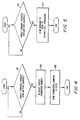
- This battery charger call forwarding feature will now be described with respect to FIG. 1 in conjunction with FIG. 4.
- the following steps are performed by circuitry in the battery charger 123 after the mobile radio terminal B 102 has been removed from the battery charger 123.
- the battery charger 123 detects that the mobile radio terminal B 102 has been removed from the battery charger 123 ("YES" PATH out of decision block 401).
- the battery charger 123 accesses its storage means and retrieves therefrom the mobile radio terminal B's forwarding number (step 403).
- the battery charger 123 establishes the communication link 125 with the PSTN 107, and sends an appropriate command for causing the PSTN 107 to begin forwarding the wire-bound terminal C's calls to the mobile radio terminal B 102 (step 405).
- the automatic cancelling of call forwarding from the wire-bound terminal C 103 to the mobile radio terminal B 102 will now be described with respect to FIG. 1 in conjunction with FIG. 5.
- the following steps are performed by circuitry in the battery charger 123 after the mobile radio terminal B 102 has been inserted into the battery charger 123.
- the battery charger 123 detects that the mobile radio terminal B 102 has been inserted into the battery charger 123 ("YES" PATH out of decision block 501). Then, the battery charger 123 establishes the communication link 125 with the PSTN 107, and sends an appropriate command for causing the PSTN 107 to cancel the call forwarding of the wire-bound terminal C's calls to the mobile radio terminal B 102 (step 405).
- a verification is provided to ensure that the mobile radio terminal B 102 has been placed into an authorized receiving station.
- a verification may be desired for a number of reasons, including the need to assure that the personal communicator is not connected to inferior quality equipment that has the potential to damage the personal communicator, such as by improperly recharging the personal communicator's lithium battery, thereby causing it to catch fire or explode.
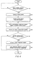
- the mobile radio terminal B 102 detects that it has been inserted into the battery charger 123 ("YES" path out of decision block 601).
- the mobile radio terminal B 102 generates a random number, using any of a number of well-known techniques (step 603).
- the communication interface between the mobile radio terminal B 102 and the battery charger 123 is then used to transfer a copy of the random number from the mobile radio terminal B 102 and the battery charger 123 (step 605).
- the mobile radio terminal B 102 and the battery charger 123 each have processing means which apply a secret cryptographic algorithm to the random number (step 607). After the battery charger 123 generates a result from the cryptographic algorithm, this result is transmitted back to the mobile radio terminal B 102 (step 609). The mobile radio terminal B 102 then compares the received result with the one it was expecting (decision block 611).
- the mobile radio terminal B 102 proceeds to invoke call forwarding by retrieving the forwarding telephone number from the storing means (step 613) and then establishing a communication channel 117 with the MSC2 105, and sending the appropriate command to the cellular communications network for initiating the call forwarding service (step 615) as described above with respect to FIG. 2.
- the mobile radio terminal B 102 will additionally disable the charging of its battery, to prevent possible damage from incompatible charging methods. As mentioned earlier, severe damage may occur by, for example, improperly recharging a lithium battery.
- the components for implementing the invention are disposed in the battery charger 123 and in the mobile radio terminal B 102.
- the battery charger 123 includes a processor 701 coupled to a random access memory (RAM) 703 and to a read only memory (ROM) 705.
- the ROM 705 stores a program for controlling operation of the processor 701.
- the RAM 703 is used for storing variables, such as a forwarding telephone number.
- the battery charger is designed to perform the automatic call forwarding as described above with respect to FIGS. 4 and 5, it includes an interface 709 to the PSTN 107.
- a power supply 707 within the battery charger 123 receives power from a main power supply, and generates therefrom suitable voltage and current levels for charging one or more batteries in the mobile radio terminal B 102.
- the battery charger 123 may additionally include a home switch 711 coupled to the processor 701.
- the purpose of the home switch 711 is to cause the processor 701 to remove any divert function that is active on the wire-bound terminal C 103.
- the home switch 711 is useful, for example, in the following situation: Suppose a first family member leaves the house with the mobile radio terminal B 102. Removal of the mobile radio terminal B 102 from the battery charger 123 automatically causes the wire-bound terminal C's telephone calls to be forwarded to the mobile radio terminal B 102 as described above with respect to FIG. 4. This is the desired function when there is no one else at home. However, if someone else is home, then the first family member would push the home switch 711 just after lifting the mobile radio terminal B 102 from the battery charger 123. This causes the processor 701 to take appropriate steps to disable the just-invoked call forwarding.
- the first family member may leave the house with the mobile terminal B 102 at a time when no one else is at home, so that call forwarding is desired and left in force. If a second family member then returns home, he can push the home switch 711 and, again, cause any call forwarding of the wire-bound terminal C's telephone calls to the mobile radio terminal B 102 to cease.
- the battery charger may be further equipped with a dual color light emitting diode (LED) 713 to indicate the forwarding status of the wire-bound terminal C 103. For example, a red light may indicate that the wire-bound terminal C 103 is diverted to the mobile radio terminal B 102. A green light may indicate that the wire-bound terminal C 103 is not diverted, that is, that it is capable of receiving incoming calls.
- LED light emitting diode
- the battery charger 123 further includes a serial communications interface 715 for coupling to a serial communications interface 717 located on the mobile radio terminal B 102.
- the purpose of each of these interfaces is to provide a mechanism for allowing each of the battery charger 123 and the mobile radio terminal B 102 to detect the presence of the other.
- a power supply port 719 on the battery charger 123 supplies the power for charging the battery located in the mobile radio terminal B 102.
- the mobile radio terminal B 102 includes a processor 721 coupled to a RAM 723, to a ROM 725 and to a non-volatile memory such as an electrically erasable programmable read only memory (EEPROM) 733.
- the ROM 725 stores a program for controlling operation of the processor 721, and may be designed to operate as described above with respect to FIGS. 2, 3 and 6.
- the RAM 723 is used for storing variables, such as a generated random number and an expected result from a cryptographic algorithm.
- the EEPROM 733 is used for storing variables, such as forwarding telephone numbers, that need to be retained even if power to the mobile radio terminal B 102 is lost.
- the mobile radio terminal B 102 further includes a charging circuit 727 for recharging at least one battery 729. Power is supplied to the charging circuit 727 by the battery charger's power supply port 719.
- the charging circuit 727 may also include a connection 731 to the processor 721 so that the processor 721 can determine whether recharging should take place, as described above, and control the charging circuit 727 accordingly.
- a mechanism may be provided to allow the user to disable the automatic call forwarding functions performed by the mobile radio terminal B 102.
- This mechanism may be in the form of a menu selection made by the user via an input/output unit (not shown) on the mobile radio terminal B 102, or it may alternatively be made by a switch (not shown) provided on the unit.
- the described embodiments include a battery charger into which the mobile radio terminal is inserted when in the vicinity of the wire-bound terminal.
- the presence of the battery charging circuitry is not essential to the invention.
- the battery charger may simply be replaced by a table stand or other receiving station for the mobile radio terminal, wherein the receiving station contains the call-forwarding circuitry described above, and is located near the wire-bound terminal.
Landscapes
- Engineering & Computer Science (AREA)
- Signal Processing (AREA)
- Computer Networks & Wireless Communication (AREA)
- Mobile Radio Communication Systems (AREA)
- Telephonic Communication Services (AREA)
Claims (4)
- Automatische Rufweiterleitungseinrichtung in einer Mobilkommunikationseinheit, wobei die automatische Rufweiterleitungseinrichtung umfasst:gekennzeichnet durch:eine Vorrichtung zum Speichern einer Weiterleitungstelefonnummer;eine Vorrichtung zum Erfassen, ob die Mobilkommunikationseinheit in einer Empfangsstation aufgenommen ist;eine Vorrichtung zum Holen der Weiterleitungstelefonnummer aus der Speichervorrichtung ansprechend auf ein Erfassen, dass die Kommunikationseinheit in die Empfangsstation eingefügt worden ist;eine Vorrichtung zum Erzeugen eines Rufweiterleitungsveranlassungsbefehls, der das Einholen der Weiterleitungstelefonnummer einschließt; undeine Vorrichtung zum Senden des erzeugten Rufweiterleitungsveranlassungsbefehls an ein Mobilkommunikationsnetz, das Rufweiterleitungsoperationen für die Mobilkommunikationseinheit steuert, undwobei die Vorrichtung zum Senden des erzeugten Rufweiterleitungsveranlassungsbefehls zu dem Mobilkommunikationsnetz nur arbeitet, wenn das Testergebnis mit dem erwarteten Ergebnis übereinstimmt.eine Vorrichtung zum Erzeugen einer Zufallszahl;eine Vorrichtung zum Senden einer Zufallszahl;eine Vorrichtung zum Senden der Zufallszahl zu der Empfangsstation;eine Vorrichtung zum Anwenden eines kryptographischen Algorithmus auf die Zufallszahl zum Erzeugen eines erwarteten Ergebnisses;eine Vorrichtung zum Empfangen eines Testergebnisses von der Empfangsstation; undeine Vorrichtung zum Vergleichen des Testergebnisses mit dem erwarteten Ergebnis,
- Automatisches Rufweiterleitungssystem, umfassend:wobei die Empfangsstation umfasst:eine Mobilkommunikationseinheit, die eine automatische Rufweiterleitungseinrichtung nach Anspruch 1 einschließt; undeine Empfangsstation für die Mobilkommunikationseinheit,eine Vorrichtung zum Kooperieren mit der Erfassungsvorrichtung in der Mobilkommunikationseinheit, um die Erfassungsvorrichtung in die Lage zu versetzen, zu erfassen, ob die Mobilkommunikationseinheit in die Empfangsstation eingefügt ist,eine Vorrichtung zum Empfangen der Zufallszahl von der Mobilkommunikationseinheit;eine Vorrichtung zum Anwenden des kryptographischen Algorithmus auf die Zufallszahl zum Erzeugen des Testergebnisses; undeine Vorrichtung zum Zuführen des Testergebnisses zu der Mobilkommunikationseinheit.
- Verfahren zum automatischen Weiterleiten von Rufen von einer Mobilkommunikationseinheit zu einem hartverdrahteten Endgerät, wobei das Verfahren die Schritte umfasst:gekennzeichnet durch die Schritte :in der Mobilkommunikationseinheit, Speichern einer Weiterleitungstelefonnummer, die die Telefonnummer des hartverdrahteten Endgerätes ist;Erfassen, ob die Mobilkommunikationseinheit in einer Empfangsstation (601) eingefügt ist;Holen der gespeicherten Weiterleitungstelefonnummer ansprechend auf das Erfassen, dass die Mobilkommunikationseinheit in die Empfangsstation (613) eingefügt ist;Erzeugen eines Rufweiterleitungsveranlassungsbefehls, der die geholte Weiterleitungstelefonnummer einschließt; undSenden des erzeugten Rufweiterleitungsveranlassungsbefehls zu einem Mobilkommunikationsnetz, das Rufweiterleitungsvorgänge für die Mobilkommunikationseinheit (615) steuert,wobei der Schritt des Sendens des erzeugten Rufweiterleitungsveranlassungsbefehls zu dem Mobilkommunikationsnetz nur ausgeführt wird, wenn das Testergebnis mit dem erwarteten Ergebnis übereinstimmt.Erzeugen einer Zufallszahl in der Mobilkommunikationseinheit (603);Senden der Zufallszahl zu der Empfangsstation (605);in der Mobilkommunikationseinheit, Anwenden eines kryptographischen Algorithmus auf die Zufallszahl zum Erzeugen eines erwarteten Ergebnisses (607);Empfangen eines Testergebnisses von der Empfangsstation (609); undVergleichen des Testergebnisses mit dem erwarteten Ergebnis (611),
- Verfahren nach Anspruch 3, ferner die Schritte umfassend:in der Empfangsstation:Empfangen der Zufallszahl von der Mobilkommunikationseinheit;Anwenden des kryptographischen Algorithmus auf die Zufallszahl zum Erzeugen eines Testergebnisses; undZuführen des Testergebnisses zu der Mobilkommunikationseinheit.
Applications Claiming Priority (3)
| Application Number | Priority Date | Filing Date | Title |
|---|---|---|---|
| US64457396A | 1996-05-10 | 1996-05-10 | |
| US644573 | 1996-05-10 | ||
| PCT/SE1997/000757 WO1997043864A1 (en) | 1996-05-10 | 1997-05-06 | Call forwarding function for a portable radio communications device |
Publications (2)
| Publication Number | Publication Date |
|---|---|
| EP0897645A1 EP0897645A1 (de) | 1999-02-24 |
| EP0897645B1 true EP0897645B1 (de) | 2005-08-31 |
Family
ID=24585472
Family Applications (1)
| Application Number | Title | Priority Date | Filing Date |
|---|---|---|---|
| EP97922276A Expired - Lifetime EP0897645B1 (de) | 1996-05-10 | 1997-05-06 | Rufweiterleitungsfunktion für eine tragbare funkkommunikationseinrichtung |
Country Status (7)
| Country | Link |
|---|---|
| EP (1) | EP0897645B1 (de) |
| JP (1) | JP2000510304A (de) |
| CN (1) | CN1106129C (de) |
| AU (1) | AU721171B2 (de) |
| BR (1) | BR9708938A (de) |
| EE (1) | EE04135B1 (de) |
| WO (1) | WO1997043864A1 (de) |
Families Citing this family (23)
| Publication number | Priority date | Publication date | Assignee | Title |
|---|---|---|---|---|
| GB2337411B (en) * | 1998-05-13 | 2002-09-18 | Nec Technologies | Interconnect controller |
| MXPA99011343A (es) * | 1999-05-18 | 2004-09-01 | Vtech Communications Ltd | Metodo para enviar automaticamente llamadas destinadas a telefono celular a otro numero telefonico. |
| FR2794331B1 (fr) * | 1999-05-25 | 2001-06-22 | Sagem | Ensemble de routage d'appels telephoniques pour un reseau telephonique local, routeur et chargeur de telephone cellulaire associes |
| US6236326B1 (en) * | 1999-10-29 | 2001-05-22 | Vtech Telecommunications, Ltd. | Method and apparatus for intelligently signaling a battery charge condition in a wireless telephone |
| DE19960964A1 (de) * | 1999-12-17 | 2001-06-21 | Siemens Ag | Telekommunikations-Endgeräte und Verfahren zur Steuerung der Rufumleitung zwischen Telekommunikations-Endgeräten |
| EP1111886A1 (de) * | 1999-12-23 | 2001-06-27 | Sony International (Europe) GmbH | Telefonapparat |
| US6405042B1 (en) * | 2000-02-03 | 2002-06-11 | Lucent Technologies Inc. | Provision of cellular/wire-line service |
| CN100375565C (zh) | 2000-08-04 | 2008-03-12 | 西门子公司 | 控制通信系统的呼叫转移的方法、移动终端设备和基站 |
| US7437148B1 (en) * | 2001-06-08 | 2008-10-14 | Vaghi Family Intellectual Properties, Llc | Personal communications system and method |
| US6970696B1 (en) * | 2001-07-03 | 2005-11-29 | At&T Corp. | Method and apparatus for controlling a network device |
| CA2365559A1 (en) * | 2001-12-18 | 2003-06-18 | Michel Deschenes | Method and system for automatically providing handset operational status information to a wireless carrier when interfaced to a hybrid fixed wireless device |
| CN100421498C (zh) * | 2002-09-04 | 2008-09-24 | 英华达(上海)电子有限公司 | 短消息呼叫转移方法 |
| CN100454953C (zh) * | 2003-07-06 | 2009-01-21 | 艾威梯软件技术(北京)有限公司 | 一种实现蓝牙手机自动呼叫转移的设备及其方法 |
| GB0322973D0 (en) * | 2003-10-01 | 2003-11-05 | Siemens Ag | Telephone call processing |
| CN1553687A (zh) * | 2003-12-16 | 2004-12-08 | 刚 阮 | 使移动电话可以在来电时选择转移至哪个电话号码的方法 |
| KR101067304B1 (ko) | 2003-12-25 | 2011-09-23 | 오끼 덴끼 고오교 가부시끼가이샤 | 교환처리 시스템 |
| KR100619901B1 (ko) * | 2004-09-18 | 2006-09-12 | 엘지전자 주식회사 | 이동 통신 단말기의 호 전환 표시 상태 처리 방법 |
| KR100608827B1 (ko) * | 2004-09-18 | 2006-08-09 | 엘지전자 주식회사 | 이동 통신 단말기의 호 전환 표시 상태 처리 방법 |
| CN100428838C (zh) * | 2004-09-24 | 2008-10-22 | 普天信息技术研究院 | 一种电信终端接入选择的方法 |
| US8971865B2 (en) * | 2007-09-26 | 2015-03-03 | Google Inc. | Converged cordless and cellular phone system |
| US8614560B2 (en) * | 2010-03-26 | 2013-12-24 | Nokia Corporation | Method and apparatus for determining interaction mode |
| CN104144397B (zh) * | 2013-05-08 | 2019-09-13 | 南京中兴新软件有限责任公司 | 一种取消被设定为呼叫转移号码的方法及核心网设备 |
| CN106162585A (zh) * | 2015-04-08 | 2016-11-23 | 中兴通讯股份有限公司 | 一种呼叫转移的方法、装置和系统 |
Family Cites Families (3)
| Publication number | Priority date | Publication date | Assignee | Title |
|---|---|---|---|---|
| GB9301769D0 (en) * | 1993-01-29 | 1993-03-17 | Ind Limited W | Opticla system |
| FR2709034B1 (fr) * | 1993-08-13 | 1995-09-08 | Alcatel Mobile Comm France | Procédé de transfert d'appels à partir d'une station mobile vers un autre poste, et dispositif de recharge pour la mise en Óoeuvre de ce procédé. |
| GB2284727A (en) * | 1993-12-09 | 1995-06-14 | Stephen Robin Temple | Portable radio telephone capable of receiving calls over fixed telephone network |
-
1997
- 1997-05-06 AU AU27990/97A patent/AU721171B2/en not_active Ceased
- 1997-05-06 CN CN97196009A patent/CN1106129C/zh not_active Expired - Fee Related
- 1997-05-06 BR BR9708938A patent/BR9708938A/pt not_active IP Right Cessation
- 1997-05-06 WO PCT/SE1997/000757 patent/WO1997043864A1/en not_active Ceased
- 1997-05-06 EP EP97922276A patent/EP0897645B1/de not_active Expired - Lifetime
- 1997-05-06 EE EE9800379A patent/EE04135B1/xx not_active IP Right Cessation
- 1997-05-06 JP JP09540787A patent/JP2000510304A/ja not_active Ceased
Also Published As
| Publication number | Publication date |
|---|---|
| EE04135B1 (et) | 2003-08-15 |
| EE9800379A (et) | 1999-04-15 |
| JP2000510304A (ja) | 2000-08-08 |
| CN1223778A (zh) | 1999-07-21 |
| AU2799097A (en) | 1997-12-05 |
| AU721171B2 (en) | 2000-06-22 |
| EP0897645A1 (de) | 1999-02-24 |
| CN1106129C (zh) | 2003-04-16 |
| WO1997043864A1 (en) | 1997-11-20 |
| BR9708938A (pt) | 1999-08-03 |
Similar Documents
| Publication | Publication Date | Title |
|---|---|---|
| EP0897645B1 (de) | Rufweiterleitungsfunktion für eine tragbare funkkommunikationseinrichtung | |
| CA2157068C (en) | Apparatus and method for mobile (e.g., cellular or wireless) telephone call handover and impersonation | |
| KR970002755B1 (ko) | Pabx 무선 전화 시스템 | |
| US6480714B1 (en) | Cellular docking station | |
| JPH0334702B2 (de) | ||
| US7463726B2 (en) | Remotely selecting an economical communications transmission medium | |
| CN1225214A (zh) | 无绳电话设备 | |
| US7496187B2 (en) | In-bound call directed telephone station and method of directing a telephone station based on an in-bound call | |
| US4794636A (en) | Method and apparatus for code matching the base and mobile unit of a cordless telephone set | |
| EP0952742B1 (de) | Punkt-zu-Punkt-zu-Punkt-Anruf | |
| US6470082B1 (en) | Communications system using portable recording medium | |
| US6804342B1 (en) | Procedure for establishment of communication between two data transmission terminals and terminal for the embodiment of the procedure | |
| KR100450858B1 (ko) | 휴대용무선통신장치의호발송기능 | |
| KR19990004344A (ko) | 이동통신시스템의 사용자 고유번호를 이용한 휴대기 사용방법 | |
| JP3313662B2 (ja) | 携帯端末 | |
| KR100248103B1 (ko) | 간이교환 시스템에서의 착신호 전환 방법 | |
| KR19990014044A (ko) | 호출 전송 방법 및 장치 | |
| JP4462811B2 (ja) | 電話交換システム | |
| JPH06326786A (ja) | 移動通信システムにおける端末電話機クラス識別方式 | |
| JPH1141351A (ja) | 交換機 | |
| JPH0595416A (ja) | Disa機能付き交換システム | |
| KR19980075415A (ko) | 자동응답전화기의 메시지 전달장치 및 그 방법 | |
| JPH10112755A (ja) | 異種回線網間交換接続装置 | |
| JPH04185049A (ja) | 内線単位課金方式 | |
| JPH0233249A (ja) | 限定発信電話機 |
Legal Events
| Date | Code | Title | Description |
|---|---|---|---|
| PUAI | Public reference made under article 153(3) epc to a published international application that has entered the european phase |
Free format text: ORIGINAL CODE: 0009012 |
|
| 17P | Request for examination filed |
Effective date: 19981024 |
|
| AK | Designated contracting states |
Kind code of ref document: A1 Designated state(s): ES GB IT SE |
|
| 17Q | First examination report despatched |
Effective date: 20030929 |
|
| RAP1 | Party data changed (applicant data changed or rights of an application transferred) |
Owner name: TELEFONAKTIEBOLAGET LM ERICSSON (PUBL) |
|
| GRAP | Despatch of communication of intention to grant a patent |
Free format text: ORIGINAL CODE: EPIDOSNIGR1 |
|
| GRAS | Grant fee paid |
Free format text: ORIGINAL CODE: EPIDOSNIGR3 |
|
| GRAA | (expected) grant |
Free format text: ORIGINAL CODE: 0009210 |
|
| AK | Designated contracting states |
Kind code of ref document: B1 Designated state(s): ES GB IT SE |
|
| PG25 | Lapsed in a contracting state [announced via postgrant information from national office to epo] |
Ref country code: IT Free format text: LAPSE BECAUSE OF FAILURE TO SUBMIT A TRANSLATION OF THE DESCRIPTION OR TO PAY THE FEE WITHIN THE PRESCRIBED TIME-LIMIT;WARNING: LAPSES OF ITALIAN PATENTS WITH EFFECTIVE DATE BEFORE 2007 MAY HAVE OCCURRED AT ANY TIME BEFORE 2007. THE CORRECT EFFECTIVE DATE MAY BE DIFFERENT FROM THE ONE RECORDED. Effective date: 20050831 |
|
| REG | Reference to a national code |
Ref country code: GB Ref legal event code: FG4D |
|
| PG25 | Lapsed in a contracting state [announced via postgrant information from national office to epo] |
Ref country code: SE Free format text: LAPSE BECAUSE OF FAILURE TO SUBMIT A TRANSLATION OF THE DESCRIPTION OR TO PAY THE FEE WITHIN THE PRESCRIBED TIME-LIMIT Effective date: 20051130 |
|
| PLBE | No opposition filed within time limit |
Free format text: ORIGINAL CODE: 0009261 |
|
| STAA | Information on the status of an ep patent application or granted ep patent |
Free format text: STATUS: NO OPPOSITION FILED WITHIN TIME LIMIT |
|
| 26N | No opposition filed |
Effective date: 20060601 |
|
| PGFP | Annual fee paid to national office [announced via postgrant information from national office to epo] |
Ref country code: GB Payment date: 20080529 Year of fee payment: 12 |
|
| PG25 | Lapsed in a contracting state [announced via postgrant information from national office to epo] |
Ref country code: ES Free format text: LAPSE BECAUSE OF NON-PAYMENT OF DUE FEES Effective date: 20060531 |
|
| GBPC | Gb: european patent ceased through non-payment of renewal fee |
Effective date: 20090506 |
|
| PG25 | Lapsed in a contracting state [announced via postgrant information from national office to epo] |
Ref country code: GB Free format text: LAPSE BECAUSE OF NON-PAYMENT OF DUE FEES Effective date: 20090506 |