EP0897760B1 - Dispositif de convoyage dans un système d'inspection de réceipients - Google Patents
Dispositif de convoyage dans un système d'inspection de réceipients Download PDFInfo
- Publication number
- EP0897760B1 EP0897760B1 EP98830455A EP98830455A EP0897760B1 EP 0897760 B1 EP0897760 B1 EP 0897760B1 EP 98830455 A EP98830455 A EP 98830455A EP 98830455 A EP98830455 A EP 98830455A EP 0897760 B1 EP0897760 B1 EP 0897760B1
- Authority
- EP
- European Patent Office
- Prior art keywords
- containers
- conveyor
- deviation
- section
- travel
- Prior art date
- Legal status (The legal status is an assumption and is not a legal conclusion. Google has not performed a legal analysis and makes no representation as to the accuracy of the status listed.)
- Expired - Lifetime
Links
- 238000007689 inspection Methods 0.000 title claims abstract description 26
- 230000000284 resting effect Effects 0.000 claims abstract description 3
- 239000000463 material Substances 0.000 claims description 2
- 238000005286 illumination Methods 0.000 description 6
- 238000011144 upstream manufacturing Methods 0.000 description 4
- 239000011521 glass Substances 0.000 description 2
- 230000007246 mechanism Effects 0.000 description 2
- 230000003213 activating effect Effects 0.000 description 1
- 238000004458 analytical method Methods 0.000 description 1
- 238000005452 bending Methods 0.000 description 1
- 230000002950 deficient Effects 0.000 description 1
- 238000009434 installation Methods 0.000 description 1
- 239000007788 liquid Substances 0.000 description 1
- 238000012423 maintenance Methods 0.000 description 1
- 230000007257 malfunction Effects 0.000 description 1
- 230000000717 retained effect Effects 0.000 description 1
- 238000006748 scratching Methods 0.000 description 1
- 230000002393 scratching effect Effects 0.000 description 1
Images


Classifications
-
- B—PERFORMING OPERATIONS; TRANSPORTING
- B65—CONVEYING; PACKING; STORING; HANDLING THIN OR FILAMENTARY MATERIAL
- B65G—TRANSPORT OR STORAGE DEVICES, e.g. CONVEYORS FOR LOADING OR TIPPING, SHOP CONVEYOR SYSTEMS OR PNEUMATIC TUBE CONVEYORS
- B65G47/00—Article or material-handling devices associated with conveyors; Methods employing such devices
- B65G47/52—Devices for transferring articles or materials between conveyors i.e. discharging or feeding devices
- B65G47/68—Devices for transferring articles or materials between conveyors i.e. discharging or feeding devices adapted to receive articles arriving in one layer from one conveyor lane and to transfer them in individual layers to more than one conveyor lane or to one broader conveyor lane, or vice versa, e.g. combining the flows of articles conveyed by more than one conveyor
- B65G47/71—Devices for transferring articles or materials between conveyors i.e. discharging or feeding devices adapted to receive articles arriving in one layer from one conveyor lane and to transfer them in individual layers to more than one conveyor lane or to one broader conveyor lane, or vice versa, e.g. combining the flows of articles conveyed by more than one conveyor the articles being discharged or distributed to several distinct separate conveyors or to a broader conveyor lane
-
- B—PERFORMING OPERATIONS; TRANSPORTING
- B07—SEPARATING SOLIDS FROM SOLIDS; SORTING
- B07C—POSTAL SORTING; SORTING INDIVIDUAL ARTICLES, OR BULK MATERIAL FIT TO BE SORTED PIECE-MEAL, e.g. BY PICKING
- B07C5/00—Sorting according to a characteristic or feature of the articles or material being sorted, e.g. by control effected by devices which detect or measure such characteristic or feature; Sorting by manually actuated devices, e.g. switches
- B07C5/34—Sorting according to other particular properties
- B07C5/3404—Sorting according to other particular properties according to properties of containers or receptacles, e.g. rigidity, leaks, fill-level
- B07C5/3408—Sorting according to other particular properties according to properties of containers or receptacles, e.g. rigidity, leaks, fill-level for bottles, jars or other glassware
-
- B—PERFORMING OPERATIONS; TRANSPORTING
- B65—CONVEYING; PACKING; STORING; HANDLING THIN OR FILAMENTARY MATERIAL
- B65G—TRANSPORT OR STORAGE DEVICES, e.g. CONVEYORS FOR LOADING OR TIPPING, SHOP CONVEYOR SYSTEMS OR PNEUMATIC TUBE CONVEYORS
- B65G47/00—Article or material-handling devices associated with conveyors; Methods employing such devices
- B65G47/22—Devices influencing the relative position or the attitude of articles during transit by conveyors
- B65G47/24—Devices influencing the relative position or the attitude of articles during transit by conveyors orientating the articles
- B65G47/244—Devices influencing the relative position or the attitude of articles during transit by conveyors orientating the articles by turning them about an axis substantially perpendicular to the conveying plane
- B65G47/2445—Devices influencing the relative position or the attitude of articles during transit by conveyors orientating the articles by turning them about an axis substantially perpendicular to the conveying plane by means of at least two co-operating endless conveying elements
-
- B—PERFORMING OPERATIONS; TRANSPORTING
- B65—CONVEYING; PACKING; STORING; HANDLING THIN OR FILAMENTARY MATERIAL
- B65G—TRANSPORT OR STORAGE DEVICES, e.g. CONVEYORS FOR LOADING OR TIPPING, SHOP CONVEYOR SYSTEMS OR PNEUMATIC TUBE CONVEYORS
- B65G47/00—Article or material-handling devices associated with conveyors; Methods employing such devices
- B65G47/52—Devices for transferring articles or materials between conveyors i.e. discharging or feeding devices
- B65G47/64—Switching conveyors
- B65G47/644—Switching conveyors by a pivoting displacement of the switching conveyor
- B65G47/648—Switching conveyors by a pivoting displacement of the switching conveyor about a vertical axis
-
- G—PHYSICS
- G01—MEASURING; TESTING
- G01N—INVESTIGATING OR ANALYSING MATERIALS BY DETERMINING THEIR CHEMICAL OR PHYSICAL PROPERTIES
- G01N33/00—Investigating or analysing materials by specific methods not covered by groups G01N1/00 - G01N31/00
- G01N33/0078—Testing material properties on manufactured objects
- G01N33/0081—Containers; Packages; Bottles
Definitions
- the present invention relates to a conveying device in a container inspection system.
- a conveying device in a container inspection system.
- a first device illustrated in US-A-4,691,231, shows containers conveyed on a transparent belt on which they rest with their base, but the transparent belt is subject to wear and scratching which impair the transparency thereof and may result in reading errors in the station inspecting the bottom.
- a second device for checking the bottom is known from EP-A-0,124,164 which, in the bottom inspection zone, shows the bottles kept in the suspended condition by pairs of continuous belt conveyors so that the main conveyor belt is interrupted in this zone and there is a vertical free passage for the inspection light ray.
- EP-B-0415154 which also performs checking of the side surface of the containers prior to and after interruption of the main conveyor and in said interruption uses continuous belt conveyors with different speeds so as to produce a rotation of the containers during their forwards movement.
- This second type of device has the drawback that it requires essentially three separate conveyors, namely the conveyor for the interruption section and the two conveyors respectively for the section upstream and the section downstream of said interruption, with obvious complications from the point of view of the movement and the synchronization of the conveyors.
- interruption zone and the conveyors are positioned so that any stoppage of the middle conveyor causes a stoppage of the entire line since it is not possible to pass from the upstream conveyor to the downstream conveyor, bypassing the interruption zone.
- a third device consists of a single conveyor of the rectilinear type which envisages, in zone where inspection of the bottom of the containers is performed, operation of a curved deviation apparatus which forces the containers to be conveyed, in the suspended condition, along a curved path outside the conveyor and then return onto said conveyor once inspection of the bottom has been completed.
- the deviation apparatus which consists of a star-wheel conveyor which grips the containers by the home and/or by the body, or of lateral guides which create an obligatory path for the containers, are however not an effective solution and it is not desirable that the containers should pass from a rectilinear conveying movement to a conveying movement along a curved path, which is difficult to adjust in the event of a change in the shape or size of the containers.
- said deviation apparatus cannot be bypassed in the case where inspection is not required or the inspection device is faulty and does not allow the containers to be brought into a storage zone downstream of the inspection zone.
- the devices according to the known art have, moreover, in most cases, the additional drawback of division of the rectilinear conveyor belt, namely the rectilinear belt is composed of two sections, one upstream and one downstream of the inspection zone and this makes it necessary to provide two drive systems: one for the belt downstream and one for the rectilinear belt upstream of the deviation, and moreover in the vicinity of the end zone of the rectilinear section, bending of the conveyor links is often the cause of sudden movements of the containers.
- the object of the present invention is that of eliminating the abovementioned drawbacks and providing a conveying device which allows inspection of the bottom, while keeping the containers in the suspended condition with the bottom being able to be inspected in a perfect manner.
- a further object is that of achieving this in an extremely simple and low-cost manner and such that it may be disconnected from the rest of the plant in the event that inspection of the bottom is not required.
- Another object is that of avoiding sudden movements of the containers along the various conveying sections.
- a first solution which is rather costly, envisages the use of several telecameras which detect the image of the container while the latter advances on a rectilinear conveyor belt.
- Another solution envisages the use of a single movable side belt and a fixed wall: the containers gripped between fixed wall and movable belt advance rotating about themselves.
- a further solution envisages the use of a single-path rectilinear conveyor which widens, producing an automatic rotation of containers during their forwards movement and positioning in an adjacent zig-zag configuration similar to a quincuncial arrangement.
- This solution has the drawback, however, that it requires a certain thrust applied to the containers themselves and is not activated for the first containers, i.e. until the outlet channel, where the containers proceed again along a single path in a straight row, is fully occupied. Moreover, it is difficult to control the amount of the angle of rotation.
- FR 2639621 discloses a well known conveyor of the type single/multiple-path provided with a deviation device to convey the containers in one of the three outlet lines. This device can not perform an inspection of the containers in suspended condition.
- US 4915237 is another well known device of single-path type wherein the containers are inspected in a suspended condition.
- this device has the drawbacks of the prior art already cited in the application, because it needs two separated conveyors (one before and one after the inspection section) with separated motorisations and it can not avoid the suspended inspection zone.
- the object of the present invention is to eliminate the possible drawbacks of the solutions mentioned above and in particular to provide a device which is able to produce a controlled and adjustable rotation of the containers in an extremely simple and low-cost manner, also applicable to numerous inspection systems which already exist.
- 1 denotes a conveyor 1 comprising a first single-path travel section 2 and a second multiple-path travel section 3 for conveying containers 4, for example glass bottles.
- the conveyor 1 is a belt conveyor of a substantially known type.
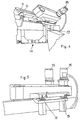
- Said zone 6 is provided with a device for inspecting the bottom of the containers, consisting of an illumination device 7 and a telecamera 8, but a device for inspecting the inlet opening may also be combined therewith, said device consisting of an additional telecamera 8a provided with an illumination device in accordance with that shown in Figure 3.
- the deviation conveyor in the example illustrated consists of two pairs of movable belts 9 wound on pulleys and acting on the body of the containers 4, but may also comprise a single pair of belts, and additional belts acting on the neck may be provided, or else, in accordance with a variant not illustrated, the use of belts 9 combined with a fixed wall between which the containers are retained while they advance may be envisaged.
- the containers 4 supplied from the first section 2 of the conveyor 1 are taken up by the deviation conveyor 5 which moves them in the suspended condition in the zone 6 where inspection of the containers occurs and then conveys them towards the second section 3 of the conveyor 1 where there is a storage area 10 created by means of a contact element 11 which may be removed if necessary.
- the deviation conveyor 5 may be displaced, by rotating it with respect to its pivoting axis 12 so that the containers are not subject to any deviation.
- the movable belts 9 may be widened (by means of actuator means denoted in their entirety by 14) so as to make the deviation conveyor 5 inactive: the containers are moved exclusively by the conveyor 1 and follow a rectilinear path, as illustrated in Figure 2.
- a thruster device 13 may be provided, said device expelling the containers 4 considered to be defective. Obviously the thruster device 13 is controlled by a PLC connected to the device for inspecting the bottom and/or the inlet opening of the containers.
- the deviation conveyor 5 is formed so as to be easily accessible for maintenance operations.
- the deviation conveyor 5 is composed of two parts which may open rotating about their axis via the use of a pair of hinges 15.
- the two half parts are in fact hinged with a frame 17 of the device so that they may at least partially open and be folded back with a rotation about an axis parallel to the direction of conveying of the containers in the device.
- the present device which adopts an original deviation conveyor 5 which deviates laterally the containers onto a rectlinear section where they travel suspended, combines the advantages of linear travel (rapidity of change in shape or size since it is sufficient to widen the travel zone between the belts) with the advantages of the single conveyor 1 of the continuous type also in the zone where the device is applied.
- This latter feature in fact allows the avoidance of sudden movements of the containers, the presence of a single drive system for the conveyor 1 and the possibility of activating lateral deviation only when it is actually required.
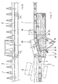
- the first part of the deviation conveyor 5 may be completed, in accordance with that shown in Figures 6 to 10, by a second part 25 which conveys the containers 4 from the first travel section 2 to the second travel section 3, causing them to rotate about themselves through a certain angle.
- the containers 4 are supplied, in the example illustrated in Figure 7, from a bottom inspection apparatus 8 of the known type, and in particular from the first part 5 of the deviation conveyor, but may also be supplied directly by the conveyor, as illustrated for example in Figure 9.
- the deviation conveyor consists of a single part coinciding with the second part 25.
- the present invention allows the original rotation of the containers 4 by means of simple contact and friction against the deviation conveyor during their forwards movement on the conveyor 1.
- the deviation conveyor 5 comprises a shaped guide made of material which is rubbery and in any case such as to produce a sufficient friction with the containers, and the operating profile of said guide is wavy or serrated or sawtoothed.
- the inclination of the guide is equal to about 10° - 35° with respect to the direction of the forwards movement of the first section 2.
- the rotation of the containers is preferably through at least 90° and may be varied by varying the inclination, the length and the shape of the guide with respect to the direction of conveying into the inlet of the deviation device.
- the guide is supported by arms 26 provided with articulations 21 and secured to fixed supports 27.
- the second travel section 3 comprises multiple paths, each with its own speed which may be different from that of the adjacent paths.
- the conveying paths are arranged with progressively increasing speeds in the direction of forwards movement of the containers (i.e. the conveying path closest to the outlet path has a speed which is greater than that of the conveying path adjacent to the inlet path) so as to maintain a constant thrusting force and compensate for the movement of the containers towards one another.
- the device according to the present invention it is possible to impart an automatic, controllable and adjustable rotation to the containers passing through on a conveyor during the step involving inspection of the wall or the contents, in an extremely simple and low-cost manner, which does not require any drive system or special kinematic mechanism.
- the positions of the telecamera 19 and the illumination device 20 with respect to the guide may be inverted and in particular the arms 26 may support the illumination device 20 with the guide at the base, so that the entire side surface of the containers is visible by the telecamera and is not partially covered by the guide and in such a way as to avoid additional support means for the illumination device.
Landscapes
- Engineering & Computer Science (AREA)
- Mechanical Engineering (AREA)
- Health & Medical Sciences (AREA)
- Life Sciences & Earth Sciences (AREA)
- Chemical & Material Sciences (AREA)
- Food Science & Technology (AREA)
- Medicinal Chemistry (AREA)
- Physics & Mathematics (AREA)
- Analytical Chemistry (AREA)
- Biochemistry (AREA)
- General Health & Medical Sciences (AREA)
- General Physics & Mathematics (AREA)
- Immunology (AREA)
- Pathology (AREA)
- Investigating Materials By The Use Of Optical Means Adapted For Particular Applications (AREA)
- Automatic Analysis And Handling Materials Therefor (AREA)
- Discharge Of Articles From Conveyors (AREA)
- Sorting Of Articles (AREA)
- Attitude Control For Articles On Conveyors (AREA)
- Specific Conveyance Elements (AREA)
Claims (11)
- Dispositif de convoyage dans un système d'inspection de récipients, du type comprenant un convoyeur (1) de récipients, ayant au moins une première section de course à trajectoire unique (2) et une seconde section de course à trajectoire multiple (3) définissant au moins une ligne de convoyage continue de la première section (2) à la seconde section (3) de manière à définir un unique dispositif de convoyage, un convoyeur de déviation (5) conformé de manière à convoyer les récipients (4) de la première section de course à trajectoire unique (2) à la seconde section de course à trajectoire multiple (3), caractérisé en ce que le convoyeur de déviation (5) est conformé de manière à faire passer les récipients (4) au travers d'une zone (6) dans laquelle lesdits récipients (4) se déplacent en condition suspendue sans reposer sur leur base.
- Dispositif selon la revendication 1, dans lequel le convoyeur de déviation (5) est conformé de manière à être fixé en rotation en une extrémité (12) afin de pouvoir assumer de différentes positions de déviation ainsi qu'une position le plaçant dans la même direction que celle du convoyeur (1) dans le cas ou aucune déviation ne soit nécessaire.
- Dispositif selon la revendication 1, dans lequel ledit convoyeur de déviation (5) comprend au moins une paire de courroies ou bandes de convoyage (9) qui agissent latéralement sur les récipients (4) dans la région du corps et/ou du col.
- Dispositif selon la revendication 3, dans lequel lesdites courroies ou bandes (9) ont des mouvements dans des directions opposées ou à des vitesses différentes de manière à produire une rotation des récipients (4) pendant leur mouvement vers l'avant dans le convoyeur de déviation (5).
- Dispositif selon n'importe laquelle des revendications précédentes, dans lequel un appareil pour inspecter le fond des récipients et/ou un appareil pour inspecter l'ouverture d'entrée des récipients est prévu dans la zone dans laquelle les récipients se déplacent dans une condition suspendue.
- Dispositif selon la revendication 1, dans lequel le convoyeur de déviation (5) comprend deux moitiés fixées à un châssis (17) du dispositif de manière à ce qu'elles puissent être rabattues et ouvertes au moins partiellement avec une rotation autour d'un axe parallèle à la direction de convoyage des récipients (4) dans le convoyeur de déviation (5).
- Dispositif selon la revendication 1, dans lequel est prévu un autre convoyeur de déviation (25) faisant pivoter les récipients (4) sur eux-mêmes selon un angle dépendant de l'inclinaison, de la longueur et de la forme du convoyeur de déviation (25) par rapport à la direction de la première section.
- Dispositif selon la revendication 7, dans lequel ledit convoyeur de déviation (25) comprend un guide façonné réalisé en un matériau caoutchouteux ou dans tous les cas conçu pour produire la rotation des récipients (4) au moyen du simple contact et de la friction de ces derniers contre le guide pendant leur mouvement vers l'avant sur le convoyeur (1).
- Dispositif selon la revendication 7, dans lequel ledit convoyeur de déviation (25) comprend des bras de supports articulables (7) fixés sur des supports fixes (7), la forme et l'inclinaison du convoyeur de déviation (25) étant variables au moyen de ces bras articulables.
- Dispositif selon la revendication 7, dans lequel l'inclinaison du convoyeur de déviation (1) varie de 10° à 35° par rapport à la direction du mouvement vers l'avant des récipients dans la première section de course (2).
- Dispositif selon la revendication 1, dans lequel sont prévus des moyens d'actionnement (14) pour un élargissement des courroies mobiles (9) de manière à rendre le convoyeur de déviation (5) inactif.
Applications Claiming Priority (4)
| Application Number | Priority Date | Filing Date | Title |
|---|---|---|---|
| ITPR970043 | 1997-07-29 | ||
| IT97PR000043 IT1294102B1 (it) | 1997-07-29 | 1997-07-29 | Dispositivo di trasporto in ispettore di contenitori. |
| ITPT970067 | 1997-11-19 | ||
| ITPT970067 | 1997-11-19 |
Publications (2)
| Publication Number | Publication Date |
|---|---|
| EP0897760A1 EP0897760A1 (fr) | 1999-02-24 |
| EP0897760B1 true EP0897760B1 (fr) | 2003-07-02 |
Family
ID=26331944
Family Applications (1)
| Application Number | Title | Priority Date | Filing Date |
|---|---|---|---|
| EP98830455A Expired - Lifetime EP0897760B1 (fr) | 1997-07-29 | 1998-07-27 | Dispositif de convoyage dans un système d'inspection de réceipients |
Country Status (3)
| Country | Link |
|---|---|
| EP (1) | EP0897760B1 (fr) |
| AT (1) | ATE244076T1 (fr) |
| DE (1) | DE69815963T2 (fr) |
Cited By (1)
| Publication number | Priority date | Publication date | Assignee | Title |
|---|---|---|---|---|
| WO2024104745A1 (fr) * | 2022-11-15 | 2024-05-23 | Alta Vision, SRL | Système et procédé d'inspection de récipients cylindriques |
Families Citing this family (14)
| Publication number | Priority date | Publication date | Assignee | Title |
|---|---|---|---|---|
| FR2846314B1 (fr) | 2002-10-25 | 2005-08-19 | Bsn Glasspack | Machine de deplacement de recipients devant des postes de controle |
| BE1016367A3 (nl) * | 2004-12-22 | 2006-09-05 | Willems Engineering Bv Met Bep | Sorteerinrichting. |
| DE102007054822A1 (de) * | 2007-11-16 | 2009-05-20 | Heidelberger Druckmaschinen Ag | Vorrichtung zum Drehen flacher Gegenstände, insbesondere von Faltschachtelzuschnitten |
| JP2012153423A (ja) * | 2011-01-28 | 2012-08-16 | Mitsubishi Heavy Industries Food & Packaging Machinery Co Ltd | ボトル回転装置およびボトル回転装置を備えるボトル搬送装置 |
| JP2011213417A (ja) * | 2011-07-12 | 2011-10-27 | Mitsubishi Heavy Ind Ltd | ボトルキャップ殺菌装置 |
| DE102013209451A1 (de) * | 2013-05-22 | 2014-11-27 | Krones Ag | Inspektionsmaschine für Behälter und Verfahren zum Umlenken von Behältern aus einer ersten in eine zweite Transportrichtung |
| EP2818435B1 (fr) * | 2013-06-28 | 2016-04-06 | Tetra Laval Holdings & Finance S.A. | Système de distribution destiné à une unité servant à transférer des emballages scellés |
| CN104003157B (zh) * | 2014-05-22 | 2016-03-23 | 杭州中亚机械股份有限公司 | 一种翻转输送装置 |
| DE102018215416A1 (de) * | 2018-09-11 | 2020-03-12 | Symplex Vision Systems Gmbh | Behälterinspektionsvorrichtung |
| EP4053050A1 (fr) * | 2021-03-05 | 2022-09-07 | Europool S.r.l. | Module de traitement pour le traitement des récipients |
| CN116692457B (zh) * | 2023-07-24 | 2024-04-30 | 江苏浩视科技有限公司 | 一种瓶体检验排列设备 |
| DE102023133768A1 (de) * | 2023-12-04 | 2025-06-05 | Heuft Systemtechnik Gmbh | Inspektionsvorrichtung für Behälter |
| EP4640588A1 (fr) * | 2024-04-25 | 2025-10-29 | Movu | Système d'inspection pour inspecter des marchandises entrant ou sortant d'un stockage automatisé |
| US12515839B1 (en) * | 2024-07-05 | 2026-01-06 | Cvc Technologies Inc. | Bottle discharging and delivering equipment of counting machine |
Family Cites Families (7)
| Publication number | Priority date | Publication date | Assignee | Title |
|---|---|---|---|---|
| JPS5546172A (en) * | 1978-09-29 | 1980-03-31 | Kirin Brewery Co Ltd | Detector for foreign material |
| NL8303007A (nl) | 1983-04-22 | 1984-11-16 | Thomassen & Drijver | Inrichting voor het controleren van houders. |
| US4691231A (en) | 1985-10-01 | 1987-09-01 | Vistech Corporation | Bottle inspection system |
| US4915237A (en) * | 1986-09-11 | 1990-04-10 | Inex/Vistech Technologies, Inc. | Comprehensive container inspection system |
| FR2639621B1 (fr) * | 1988-11-28 | 1993-05-28 | Schepens Andre | Dispositif pour le deplacement et la distribution de conditionnement |
| NL8902041A (nl) | 1989-08-10 | 1991-03-01 | Heuft Qualiplus Bv | Inrichting voor het vanuit verschillende gezichtshoeken inspecteren van voorwerpen. |
| DE29600902U1 (de) * | 1996-01-19 | 1997-05-15 | Heuft Systemtechnik Gmbh, 56659 Burgbrohl | Vorrichtung zur Inspektion von Gegenständen, insbesondere Getränkeflaschen |
-
1998
- 1998-07-27 EP EP98830455A patent/EP0897760B1/fr not_active Expired - Lifetime
- 1998-07-27 DE DE69815963T patent/DE69815963T2/de not_active Expired - Fee Related
- 1998-07-27 AT AT98830455T patent/ATE244076T1/de not_active IP Right Cessation
Cited By (1)
| Publication number | Priority date | Publication date | Assignee | Title |
|---|---|---|---|---|
| WO2024104745A1 (fr) * | 2022-11-15 | 2024-05-23 | Alta Vision, SRL | Système et procédé d'inspection de récipients cylindriques |
Also Published As
| Publication number | Publication date |
|---|---|
| DE69815963T2 (de) | 2004-04-22 |
| DE69815963D1 (de) | 2003-08-07 |
| EP0897760A1 (fr) | 1999-02-24 |
| ATE244076T1 (de) | 2003-07-15 |
Similar Documents
| Publication | Publication Date | Title |
|---|---|---|
| EP0897760B1 (fr) | Dispositif de convoyage dans un système d'inspection de réceipients | |
| US5203444A (en) | Container grouping apparatus | |
| US5255495A (en) | Adjustable girth former | |
| US7232026B2 (en) | Device for dividing a disorderly flow of cylindrical objects, for example drinks bottles, into several pathways | |
| JP2895224B2 (ja) | モジュール式の搬送装置 | |
| KR100426593B1 (ko) | 병등의회전대칭적인용기들을지지압하에이송하면서회전시키는방법및장치 | |
| JP3749482B2 (ja) | 転向機構を備えた容器移送装置 | |
| US6454101B1 (en) | Endless conveyor | |
| RU2230697C2 (ru) | Устройство и способ проверки тары на линии конвейера | |
| JP3955095B2 (ja) | 物体、特に飲料水用ボトルを検査するための装置および方法 | |
| US5012914A (en) | Diverter assembly for article conveyor | |
| US5630679A (en) | Height adjustable conveyor system | |
| US4294344A (en) | Apparatus for positioning articles between the carriers of a drag conveyor, said articles being fed in a continuous closed row | |
| EP0742165B1 (fr) | Dispositif pour trier des produits | |
| US5240100A (en) | Apparatus for receiving or transferring, vertically transporting and delivering articles such as eggs | |
| US6851250B2 (en) | Package wrapping machine with automatic package positioning prior to wrapping | |
| EP0665810B1 (fr) | Dispositif de relevement a mouvement continu | |
| EP0605423A1 (fr) | Ensemble de mise en rotation d'un article. | |
| EP0468589A1 (fr) | Dispositif de préhension d'articles comme les oeufs et appareil de transport comportant un tel dispositif | |
| NL8120035A (nl) | Inrichting voor het op zijn kop behandelen van flessen en dergelijke. | |
| US5195628A (en) | Off-loading conveying system | |
| EP0845414B1 (fr) | Dispositif pour le transfert d'articles essentiellement ronds et fragiles, tels que des oeufs | |
| US4757891A (en) | Container handling device | |
| EP0519486B1 (fr) | Dispositif pour dériver une file d'objets, en particulier pour machines emballeuses | |
| US7377375B2 (en) | Continuous motion product transfer system with conveyors |
Legal Events
| Date | Code | Title | Description |
|---|---|---|---|
| PUAI | Public reference made under article 153(3) epc to a published international application that has entered the european phase |
Free format text: ORIGINAL CODE: 0009012 |
|
| AK | Designated contracting states |
Kind code of ref document: A1 Designated state(s): AT BE CH DE DK ES FR GB IT LI NL PT SE |
|
| AX | Request for extension of the european patent |
Free format text: AL;LT;LV;MK;RO;SI |
|
| 17P | Request for examination filed |
Effective date: 19990811 |
|
| AKX | Designation fees paid |
Free format text: AT BE CH DE DK ES FR GB IT LI NL PT SE |
|
| 17Q | First examination report despatched |
Effective date: 20011031 |
|
| GRAG | Despatch of communication of intention to grant |
Free format text: ORIGINAL CODE: EPIDOS AGRA |
|
| GRAG | Despatch of communication of intention to grant |
Free format text: ORIGINAL CODE: EPIDOS AGRA |
|
| GRAH | Despatch of communication of intention to grant a patent |
Free format text: ORIGINAL CODE: EPIDOS IGRA |
|
| GRAH | Despatch of communication of intention to grant a patent |
Free format text: ORIGINAL CODE: EPIDOS IGRA |
|
| GRAA | (expected) grant |
Free format text: ORIGINAL CODE: 0009210 |
|
| AK | Designated contracting states |
Designated state(s): AT BE CH DE DK ES FR GB IT LI NL PT SE |
|
| PG25 | Lapsed in a contracting state [announced via postgrant information from national office to epo] |
Ref country code: NL Free format text: LAPSE BECAUSE OF FAILURE TO SUBMIT A TRANSLATION OF THE DESCRIPTION OR TO PAY THE FEE WITHIN THE PRESCRIBED TIME-LIMIT Effective date: 20030702 Ref country code: LI Free format text: LAPSE BECAUSE OF FAILURE TO SUBMIT A TRANSLATION OF THE DESCRIPTION OR TO PAY THE FEE WITHIN THE PRESCRIBED TIME-LIMIT Effective date: 20030702 Ref country code: FR Free format text: LAPSE BECAUSE OF FAILURE TO SUBMIT A TRANSLATION OF THE DESCRIPTION OR TO PAY THE FEE WITHIN THE PRESCRIBED TIME-LIMIT Effective date: 20030702 Ref country code: CH Free format text: LAPSE BECAUSE OF FAILURE TO SUBMIT A TRANSLATION OF THE DESCRIPTION OR TO PAY THE FEE WITHIN THE PRESCRIBED TIME-LIMIT Effective date: 20030702 Ref country code: BE Free format text: LAPSE BECAUSE OF FAILURE TO SUBMIT A TRANSLATION OF THE DESCRIPTION OR TO PAY THE FEE WITHIN THE PRESCRIBED TIME-LIMIT Effective date: 20030702 Ref country code: AT Free format text: LAPSE BECAUSE OF FAILURE TO SUBMIT A TRANSLATION OF THE DESCRIPTION OR TO PAY THE FEE WITHIN THE PRESCRIBED TIME-LIMIT Effective date: 20030702 |
|
| REG | Reference to a national code |
Ref country code: GB Ref legal event code: FG4D |
|
| REG | Reference to a national code |
Ref country code: CH Ref legal event code: EP |
|
| REF | Corresponds to: |
Ref document number: 69815963 Country of ref document: DE Date of ref document: 20030807 Kind code of ref document: P |
|
| PG25 | Lapsed in a contracting state [announced via postgrant information from national office to epo] |
Ref country code: SE Free format text: LAPSE BECAUSE OF FAILURE TO SUBMIT A TRANSLATION OF THE DESCRIPTION OR TO PAY THE FEE WITHIN THE PRESCRIBED TIME-LIMIT Effective date: 20031002 Ref country code: PT Free format text: LAPSE BECAUSE OF FAILURE TO SUBMIT A TRANSLATION OF THE DESCRIPTION OR TO PAY THE FEE WITHIN THE PRESCRIBED TIME-LIMIT Effective date: 20031002 Ref country code: GB Free format text: LAPSE BECAUSE OF NON-PAYMENT OF DUE FEES Effective date: 20031002 Ref country code: DK Free format text: LAPSE BECAUSE OF FAILURE TO SUBMIT A TRANSLATION OF THE DESCRIPTION OR TO PAY THE FEE WITHIN THE PRESCRIBED TIME-LIMIT Effective date: 20031002 |
|
| PG25 | Lapsed in a contracting state [announced via postgrant information from national office to epo] |
Ref country code: ES Free format text: LAPSE BECAUSE OF FAILURE TO SUBMIT A TRANSLATION OF THE DESCRIPTION OR TO PAY THE FEE WITHIN THE PRESCRIBED TIME-LIMIT Effective date: 20031013 |
|
| NLV1 | Nl: lapsed or annulled due to failure to fulfill the requirements of art. 29p and 29m of the patents act | ||
| REG | Reference to a national code |
Ref country code: CH Ref legal event code: PL |
|
| PLBE | No opposition filed within time limit |
Free format text: ORIGINAL CODE: 0009261 |
|
| STAA | Information on the status of an ep patent application or granted ep patent |
Free format text: STATUS: NO OPPOSITION FILED WITHIN TIME LIMIT |
|
| GBPC | Gb: european patent ceased through non-payment of renewal fee |
Effective date: 20031002 |
|
| 26N | No opposition filed |
Effective date: 20040405 |
|
| EN | Fr: translation not filed | ||
| PG25 | Lapsed in a contracting state [announced via postgrant information from national office to epo] |
Ref country code: IT Free format text: LAPSE BECAUSE OF NON-PAYMENT OF DUE FEES;WARNING: LAPSES OF ITALIAN PATENTS WITH EFFECTIVE DATE BEFORE 2007 MAY HAVE OCCURRED AT ANY TIME BEFORE 2007. THE CORRECT EFFECTIVE DATE MAY BE DIFFERENT FROM THE ONE RECORDED. Effective date: 20050727 |
|
| PGFP | Annual fee paid to national office [announced via postgrant information from national office to epo] |
Ref country code: DE Payment date: 20060925 Year of fee payment: 9 |
|
| PG25 | Lapsed in a contracting state [announced via postgrant information from national office to epo] |
Ref country code: DE Free format text: LAPSE BECAUSE OF NON-PAYMENT OF DUE FEES Effective date: 20080201 |
|
| PGRI | Patent reinstated in contracting state [announced from national office to epo] |
Ref country code: IT Effective date: 20090401 |
|
| PGFP | Annual fee paid to national office [announced via postgrant information from national office to epo] |
Ref country code: IT Payment date: 20070711 Year of fee payment: 10 |
|
| PGRI | Patent reinstated in contracting state [announced from national office to epo] |
Ref country code: IT Effective date: 20090401 |