EP0897768B1 - Conteneur pour une machine de coulée sous pression et un procédé d'élimination d'impuretés - Google Patents
Conteneur pour une machine de coulée sous pression et un procédé d'élimination d'impuretés Download PDFInfo
- Publication number
- EP0897768B1 EP0897768B1 EP98114712A EP98114712A EP0897768B1 EP 0897768 B1 EP0897768 B1 EP 0897768B1 EP 98114712 A EP98114712 A EP 98114712A EP 98114712 A EP98114712 A EP 98114712A EP 0897768 B1 EP0897768 B1 EP 0897768B1
- Authority
- EP
- European Patent Office
- Prior art keywords
- shot
- section
- plunger
- longitudinal axis
- front opening
- Prior art date
- Legal status (The legal status is an assumption and is not a legal conclusion. Google has not performed a legal analysis and makes no representation as to the accuracy of the status listed.)
- Expired - Lifetime
Links
- 238000004512 die casting Methods 0.000 title claims abstract description 17
- 239000012535 impurity Substances 0.000 title claims description 22
- 238000000034 method Methods 0.000 title claims description 7
- 230000008569 process Effects 0.000 title claims description 6
- 230000004323 axial length Effects 0.000 claims description 19
- 235000015895 biscuits Nutrition 0.000 claims description 14
- 238000006073 displacement reaction Methods 0.000 claims description 5
- 238000010438 heat treatment Methods 0.000 claims description 2
- 239000012056 semi-solid material Substances 0.000 claims 2
- 238000007790 scraping Methods 0.000 claims 1
- 239000002184 metal Substances 0.000 description 20
- 229910052751 metal Inorganic materials 0.000 description 20
- 230000002093 peripheral effect Effects 0.000 description 13
- 239000007787 solid Substances 0.000 description 8
- 230000000694 effects Effects 0.000 description 7
- 239000007788 liquid Substances 0.000 description 5
- 238000005242 forging Methods 0.000 description 4
- 238000010008 shearing Methods 0.000 description 4
- 230000009471 action Effects 0.000 description 3
- 238000005266 casting Methods 0.000 description 3
- 210000001787 dendrite Anatomy 0.000 description 3
- 238000002347 injection Methods 0.000 description 3
- 239000007924 injection Substances 0.000 description 3
- 239000000463 material Substances 0.000 description 3
- 230000000717 retained effect Effects 0.000 description 3
- 230000002195 synergetic effect Effects 0.000 description 3
- 230000009974 thixotropic effect Effects 0.000 description 3
- 238000013459 approach Methods 0.000 description 2
- 238000011835 investigation Methods 0.000 description 2
- 229910001338 liquidmetal Inorganic materials 0.000 description 2
- 238000012986 modification Methods 0.000 description 2
- 230000004048 modification Effects 0.000 description 2
- 238000012545 processing Methods 0.000 description 2
- 230000004308 accommodation Effects 0.000 description 1
- 229910045601 alloy Inorganic materials 0.000 description 1
- 239000000956 alloy Substances 0.000 description 1
- 230000008901 benefit Effects 0.000 description 1
- 230000015572 biosynthetic process Effects 0.000 description 1
- 238000004891 communication Methods 0.000 description 1
- 229910052802 copper Inorganic materials 0.000 description 1
- 239000010949 copper Substances 0.000 description 1
- 230000003467 diminishing effect Effects 0.000 description 1
- 230000002349 favourable effect Effects 0.000 description 1
- 238000004519 manufacturing process Methods 0.000 description 1
- 239000002245 particle Substances 0.000 description 1
- 239000003923 scrap metal Substances 0.000 description 1
- -1 thixotropic Substances 0.000 description 1
- 230000009466 transformation Effects 0.000 description 1
Images

Classifications
-
- B—PERFORMING OPERATIONS; TRANSPORTING
- B22—CASTING; POWDER METALLURGY
- B22D—CASTING OF METALS; CASTING OF OTHER SUBSTANCES BY THE SAME PROCESSES OR DEVICES
- B22D17/00—Pressure die casting or injection die casting, i.e. casting in which the metal is forced into a mould under high pressure
- B22D17/20—Accessories: Details
- B22D17/2015—Means for forcing the molten metal into the die
- B22D17/2023—Nozzles or shot sleeves
-
- B—PERFORMING OPERATIONS; TRANSPORTING
- B22—CASTING; POWDER METALLURGY
- B22D—CASTING OF METALS; CASTING OF OTHER SUBSTANCES BY THE SAME PROCESSES OR DEVICES
- B22D17/00—Pressure die casting or injection die casting, i.e. casting in which the metal is forced into a mould under high pressure
- B22D17/007—Semi-solid pressure die casting
-
- B—PERFORMING OPERATIONS; TRANSPORTING
- B22—CASTING; POWDER METALLURGY
- B22D—CASTING OF METALS; CASTING OF OTHER SUBSTANCES BY THE SAME PROCESSES OR DEVICES
- B22D17/00—Pressure die casting or injection die casting, i.e. casting in which the metal is forced into a mould under high pressure
- B22D17/08—Cold chamber machines, i.e. with unheated press chamber into which molten metal is ladled
- B22D17/10—Cold chamber machines, i.e. with unheated press chamber into which molten metal is ladled with horizontal press motion
-
- B—PERFORMING OPERATIONS; TRANSPORTING
- B22—CASTING; POWDER METALLURGY
- B22D—CASTING OF METALS; CASTING OF OTHER SUBSTANCES BY THE SAME PROCESSES OR DEVICES
- B22D17/00—Pressure die casting or injection die casting, i.e. casting in which the metal is forced into a mould under high pressure
- B22D17/20—Accessories: Details
- B22D17/2015—Means for forcing the molten metal into the die
- B22D17/2069—Exerting after-pressure on the moulding material
Definitions
- the invention relates to a shot sleeve and a shot unit for a die casting machine, more particularly to a cold chamber die casting machine, especially to those having a horizontal cold chamber or shot sleeve.
- the invention is particularly intended, although not limited, to the use in casting thixotropic metal.
- die casting machines this term as used herein should encompass also those machines which often are referred as “forging machines”, although forging, in its proper sense, is an operation to process solid metal, while processing semi-solid or thixotropic (sometimes referred as "superplastic") material by forging machines which employ a shot unit is more similar to die casting than to forging.
- peripheral shells When processing metal either in liquid or in semi-solid form, one problem that may arise is the formation of peripheral shells.
- Such shells form, for example, when liquid metal of high temperature is poured into a relative cold shot chamber where the periphery tends to solidify more or less, thus forming a peripheral shell which is not desirable and should not enter the cavity of a die.
- the JP-59141358 A teaches a casting method to remove oxides and to improve the heat retaining property of a molten metal by dropping a heat insulated material vessel in which the molten metal is charged onto a plunger tip and moving upward the plunger tie after bringing to a top mold into press contact with a bottom mold there by casting the molten metal.
- the shot sleeve shows a cross-section which enlarges and vessel which is crushed.
- the JP 0116255 A discloses a horizontal closing, vertical injection die casting machine, teaching an improved productivity by projecting the injection stroke limit position of the plunger chip from the upper side end face of an injection sleeve and rushing it into a biscuit. Due to the space of the biscuit part having the gap caused by the thickness of the sleeve between the outer periphery of a plunger chip and the inner wall periphery of the holes no solidified shell is cut off by the plunger chip.
- scrapping is a "dynamic" operation in that, when stripping the shell, it becomes thicker and thicker the more the plunger moves to the front opening.
- a further advantage is that with a conical biscuit remaining after the shot, it is easier to push it out, thus saving some energy.
- this "dynamic" effect is taken into account.
- this enlargement can be a stepwise enlargement, although it is preferred if the cross-section enlarges steadily in a tapering shape.
- the present invention concerns also a whole shot unit, i.e. a unit which comprises not only the shot sleeve, but also the shot plunger and its drive, and, optionally, the adjacent parts towards and before the cavity, such as those surfaces which define the sprue runner.
- the plunger's front surface comprises a conical surface tapering away from the plunger's perimetrical scrapping edge, the conical surface having a base of smaller cross-section than the perimetrical edge to form a marginal surface under an angle to said conical surface.
- the tapering front cone acts like the tip of an arrow or like a plough, urging the stripped shell into the more and more enlarging lateral space of the shot chamber.
- the sprue runner extends substantially in alignment with the direction of displacement of the shot plunger.
- the walls or surfaces which define the sprue runner form a hollow conical surface facing the interior of the shot chamber to enhance flow of liquefying semi-solid metal.
- This hollow cone matches the shape of the conical front surface of the plunger; this results in a double effect:
- the interengaging cones form a valve-like closure member which establishes a further means to prevent oxides and other impurities from flowing into the runner system.
- the biscuit can be smaller than usually, thus diminishing the losses in the form of scrap metal.
- the effect of the configuration according to the invention is the accommodation of a doubled shell of impurities, such as oxides, or of pre-solidified metal
- a process where the axial length of the enlargement of the chamber of the shot sleeve is chosen as a function of the axial length of a slug to be shaped in a die casting machine, as will become apparent from the following description.
- the present invention relates also to a process for removing impurities contained in a circumferential region of a heated slug according to claim 9.
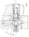
- a conventional die casting machine only part of which is shown in Fig. 1, comprises a stationary die mounting platen 1 onto which a stationary die 2 is mounted in a manner known per se and. therefore, not shown in detail.
- the stationary die 2 has an insert 3 that, together with an insert 4 of a movable die 5 defines a cavity 6 only part of which is shown in Fig. 1.
- This cavity 6 is to receive metal in liquid state that enters through a gate 7 of restricted cross-section which is in communication with a chamber 8 of a shot sleeve 9 through a sprue runner 10 and a front opening 15 of the chamber 8.
- the shot sleeve 9 has an elongated opening 11 through which metal (e.g. a semi-solid slug 12) may be inserted when a shot plunger 13 is in a retracted position at the right side of Fig. 1 beyond opening 11.
- the shot sleeve has, moreover, a projection or flange 14 for fastening it to the platen 1 before the stationary die 2 is mounted on the platen. In this way, the shot sleeve 9 is clamped in a conventional manner between the parts 1 and 2.
- the cross-section of the chamber 8 will normally be substantially circular, but other cross-sections, such as polygonal ones, are also known in the art.
- the plunger 13 has a front surface 16 surrounded by a perimetrical or peripheral edge 17 that forms an angle of 90° with respect to a longitudinal axis A of the chamber 8 and the inner wall 18 thereof. In this way, the edge 17 will act as a scrapper whenever a shell of metal forms along this inner wall 18. This applies also if liquid metal is filled into the chamber 8 through the opening 11 and freezes at the bottom of the chamber 8.
- the present inventor has considered that when the marginal or perimetrical edge 17 scraps any shell off which may be formed on the outside of the metal 12, e.g. a shell of peripheral oxides, at least the major part or substantially the entire shell should be prevented from entering the cavity 6 in order not to deteriorate the mechanical properties of the part to be formed.
- such a surface impurity accommodating space is therefore provided in that the cross-section of the chamber 8 enlarges more and more over a portion 1 of its length towards the front opening 15. The more such shell accumulates the more space is now provided to accommodate it.
- the enlargement is shown, in principle, in a linear, tapering way, but could comprise at least one step, particularly an initial step 20 starting from the minimum cross-section before the enlargement of the chamber 8 begins. Just an initial step 20 enhances doubling of any shell that might be present on the slug 12, while avoiding any squeezing effect due to a wedge-like configuration between the peripheral surface of the plunger 13 and the enlarging portion of the chamber 8.
- the tapering angle ( will be chosen according to the axial length of the slug, the thickness of a possibly existing shell, the type of metal used etc. It has been found, however, that this angle (, in practice, should be in a range of 3° to 20° at least over part of its axial length. Most preferred is it when this tapering angle is about 10° ⁇ 5°.
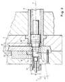
- Fig. 2 shows a more advanced condition of a modified plunger 13' in a modified front opening and sprue runner system which is more preferred.
- the plunger 13' presses against the end surface of the slug 12 to press it through a restricted front opening 15' which, preferably, aligned with the longitudinal axis A, but could, in principle, be also excentrical relative to this axis A.
- the plunger 13' has a front surface which forms a conical surface and tapers away from the perimetrical scrapping edge under a second tapering angle ⁇ which has, preferably, the same magnitude as the tapering angle ⁇ or is, at least, in the same range.
- the conical front surface 16' has a smaller cross-section or diameter than the perimetrical edge 17. Therefore, a marginal surface 16" is formed that is under an angle to the conical surface. 16'.
- this configuration is known from the above-mentioned US-A-4,144,734, it has a certain synergetic effect together with the enlarging cross-section of the shot sleeve 9 in that the marginal surface 16" enhances doubling of any shell (12' in Fig. 2) while at the same time the enlarging inner wall provides a space so that doubling is effected to the radial outside rather than to the inside, as might be the case with a conical surface 16? only.
- the conical surface 16' acts like a plough urging the shell 12' to the side towards the inner wall 18.
- the plunger 13 may have a marginal edge which joins the conical surface 16' by a rounding 18', as indicated by interrupted lines, and which forms preferably a peripheral groove (also indicated by interrupted lines).
- the outer edge 17 (or its tangent to the rounding) will form a tip, when seen in cross-section, which better scraps any shell off, on the one hand, while the rounding 18' folds or doubles it radially outside. This is particularly advantageous, because it promotes the tendency of such shell to be displaced into the radial outer space provided by the enlargement of the chamber within the shot sleeve 9.
- the cross-section of the chamber enlarges more in a section "s" adjacent the front opening 15'. In Fig. 2 this is accomplished by having the angle ⁇ enlarged to form an angle ⁇ '.
- the invention is not restricted to a mere enlargement of the widening angle, but can also be in the form of a step.
- the angles ⁇ and ⁇ ' rather than forming an edge, can join in a curved manner.
- Fig. 2 shows different magnitudes of those angles ⁇ and ⁇ , it should be understood that it is preferred if these tapering angles are mirror symmetrical with respect to the line L, at least over part of their axial length, i.e. with exception of the section "s" with the angle ⁇ ' in the embodiment shown.
- the sprue runner 10' comprises an impurity trap formed as a blind hole 21 which is substantially in alignment with the direction of displacement of the shot plunger 13 along its axis A.
- the sprue runner of Fig. 2 has then a branch conduit 10" leading upwards and sidewards into the cavity (not shown).
- a squeeze piston 22 may form the back wall of this blind hole 21.
- cyclone-like traps may be provided along the sprue runner, e.g. along the branch conduit 10".
- either the front surface of the plunger 13 may have an undercut to grip the biscuit and to tear it off when the plunger 13 is retracting, or the parts delimiting the front opening 15' can be displaced apart to release the biscuit such as by a sliding plate arrangement disclosed in DE-A-19 50 795. Both approaches are well known to those skilled in the art.
- the sprue runner system and trap are much the same as shown in Fig. 2.
- the conical front surface 16' is, in this case larger as compared with that of Fig. 2, i.e. it has an axial length at which is substantially equal to that of the hollow cone formed by the end section of the chamber that is defined by the shot sleeve 9. Since the axial length at shall act in the manner of a plough, it is preferable if the axial length at amounts to at least 50% of its width b measured normally to the longitudinal axis A. This is much more than the prior art used with the same objective to retain impurities or a pre-solidified shell.
- the axial length is about as long as the width b or even longer. It is, however, more preferable, if the axial length al amounts to at least 66% of width b, and in the most preferred case, the axial length al amounts to about 70% to 80% of said width. Furthermore, it can be seen that the angles ⁇ and ⁇ are mirror symmetrical with respect to line L. To facilitate the manufacture, the marginal surface is flat forming a 90° angle with the axis A..
- conical front surface 16' acts as a kind of valve body that co-operates with a hollow conical surface 24 formed in the piece 23 which defines the front surface 15'.
- This hollow conical surface 24 faces the chamber of the shot sleeve 9 and forms a predetermined angle with the longitudinal axis A. Preferably this angle corresponds to the angle ⁇ so that the cone 16' can (almost) engage the hollow conical surface 24 when the plunger 13 is in the end position shown in Fig. 3.
- a shot sleeve 9 When using a shot sleeve 9 according to the present invention, one should select the length 1 (Fig. 1) in relationship to the axial length of the slug 12 so as to take into account that a possible shell of impurities has to be doubled within the space provided by the enlargement of the chamber 8, on the one hand, and that, in most cases, a biscuit of a certain axial length shall remain (to provide a stock of material for an after-pressure after filling the cavity and before the metal is solidified).
- the length 1 of the shot sleeve 9 amounts to at least the length of the slug 12 used, but, ordinarily, it will be still more favorable if length of said shot sleeve amounting to approximately the two-fold of said predetermined length of said slug, or to accommodate . at least twice the volume of the portion of the metal to be retained.
- interengaging conical surfaces 16' and 24 reduces the loss of metal due to a biscuit of significant length, on the one hand, and closes the chamber of the shot sleeve 9 so as to prevent safely entering of impurities from this chamber into the runner system, on the other hand.
Landscapes
- Engineering & Computer Science (AREA)
- Mechanical Engineering (AREA)
- Injection Moulding Of Plastics Or The Like (AREA)
- Moulds For Moulding Plastics Or The Like (AREA)
- Molds, Cores, And Manufacturing Methods Thereof (AREA)
Claims (7)
- Un cylindre d'injection pour une machine à couler sous pression comprenant :caractérisé en ce que :un corps allongé creux (9) destiné à recevoir et à guider un piston d'injection (13), ledit corps (9) s'étendant le long d'un axe longitudinal (A) et définissant une chambre allongée (8) d'une coupe transversale et d'une largeur prédéterminés, lorsque l'on le mesure de façon transversale audit axe longitudinal (A) , et ayant une ouverture avant (15) pour faire face à un canal de coulée (10) d'un moule (2,5) ladite coupe transversale prédéterminée s'élargissant sur une partie (I) de sa longueur en direction de ladite ouverture avant (15) ; etun moyen d'attache (14) sur ledit corps (9) destiné à tenir le corps (9) en rapport fixe avec ledit moule (2, 5) et ladite coupe transversale prédéterminée s'élargit de plus en plus sur ladite partie (I) de sa longueur en direction de ladite ouverture avant (15), etle moyen d'attache comprend une bride (14) sur une périphérie extérieure dudit cylindre d'injection (,9), l'élargissement de ladite coupe transversale prédéterminée étant entre ladite ouverture avant (15) et ladite bride (14) ;a) l'élargissement de ladite coupe transversale prédéterminée commence avec une étape (20) d'une coupe transversale minimale, dans laquelle ladite étape (20) est dans une échelle de 2 à 8 % de la largeur minimale ;b) ladite chambre (8) comporte une première portion d'une coupe transversale circulaire engageant une racle de grattage du piston d'injection (13) et une seconde portion de coupe transversale circulaire, la seconde portion ayant un diamètre plus large que la première portion et la seconde portion s'étendant sur une distance le long dudit axe longitudinal (A) supérieur au diamètre de la première portion ;c) le corps (9) comporte une ouverture allongée (11) dans une de ses parois, l'ouverture allongée (11) ayant une longueur parallèle audit axe longitudinal (A) et une largeur perpendiculaire audit axe longitudinal (A) suffisants pour recevoir un pion (12) d'un matériau semi solide d'une taille permettant de mouler une ou plusieurs pièces, l'élargissement de ladite coupe transversale prédéterminée étant suffisant pour loger les oxydes du pion (12) et empêcher les oxydes de passer au travers de l'ouverture avant (15) pendant le die casting d'une ou plusieurs pièces.
- Une unité d'injection pour une machine à couler sous pression comprenant :caractérisé en ce que ladite coupe transversale prédéterminée forme un angle dégressif (α,α') par rapport à une ligne parallèle audit axe longitudinal (A), et s'élargit de façon monotone dans une forme bombée et ladite coupe transversale prédéterminée s'élargit d'un degré supérieur (α') dans une section (s) adjacente à ladite ouverture avant (15) et/ou l'élargissement de ladite coupe transversale prédéterminée commence avec une étape (20) d'une coupe transversale minimale, ladite étape (20) étant dans l'échelle de 2 à 8 % de sa largeur minimale.un piston d'injection (13) déplaçable le long d'un chemin prédéterminé à partir d'une position de départ d'injection vers une position finale, ledit piston (13) ayant une surface avant défini par un bord périmétrique (17), et une surface arrière ;des moyens de direction (19) destinés à diriger ledit piston d'injection (13) le long dudit chemin prédéterminé, ledit moyen de direction comportant une tige du piston d'injection (19) connectée à ladite surface arrière ;un cylindre d'injection creux allongée (8, 9) destiné à recevoir et à guider ledit piston d'injection (13), ledit cylindre d'injection (8, 9) définissant une chambre allongée (8) de coupe transversale prédéterminée le long d'un axe longitudinal (A) et ayant une ouverture avant (15) averted de ladite tige du piston d'injection (19) pour faire face à un canal de coulée (10) d'un moule (2, 5) ; ladite coupe transversale prédéterminée s'élargissant sur la partie (I) de sa longueur en direction de ladite ouverture avant (15) ; etun moyen d'attache sur ledit cylindre destiné à tenir le cylindre en rapport fixe avec ledit moule et ladite partie (I) de la longueur du corps du cylindre d'injection (9) s'élargit de plus en plus en direction de ladite ouverture avant (15)
- Unité d'injection comme revendiqué dans la revendication 2, dans laquelle au moins une des caractéristiques suivantes figure :a) ladite chambre (8) comprend une première portion d'une coupe transversale circulaire engageant une racle grattante (17) du piston d'injection (13) et une seconde portion (I) de coupe transversale circulaire, la seconde portion (I) ayant un diamètre plus large que la première portion et la seconde portion (I) s'étendant sur une distance le long duit axe longitudinal supérieure au diamètre de la première portion ;b) le moyen d'attache comprend une bride (14) sur une périphérie extérieure dudit cylindre d'injection (8, 9), l'élargissement de ladite coupe transversale prédéterminée étant entre ladite ouverture avant (15) et ladite bride (14 ;c) le cylindre d'injection (8, 9) comporte une ouverture allongée (11) dans une de ses parois, l'ouverture allongée (11) ayant une longueur parallèle audit axe longitudinal (A) et une largeur perpendiculaire audit axe longitudinal (A) suffisants pour recevoir un pion (12) d'un matériau semi solide dont la taille permet de mouler une ou plusieurs pièces, l'élargissement de ladite coupe transversale prédéterminée étant suffisant pour recevoir les oxydes du pion (12) et empêcher les oxydes de passer au travers de l'ouverture avant (15) pendant le moulage d'une ou plusieurs pièces ;d) le canal de coulée (10) s'étend de façon perpendiculaire audit axe longitudinal (A), au moins une portion du canal de coulée (10) étant définie par une partie d'une face extrême axiale du cylindre d'injection (Fig.1.)
- Unité d'injection tel que revendiqué dans n'importe laquelle des revendication 2 ou 3 dans laquelle ladite surface avant dudit piston d'injection (13) comprend une surface conique (16') s'écartant dudit bord périmétrique (17) sous un second angle dégressif (β) par rapport à une ligne (L) parallèle audit axe longitudinal (A), ladite surface conique (16') ayant une base de coupe transversale plus petite que ledit bord périmétrique (17) pour former une surface marginale (16'') sous un angle de ladite surface conique (16'), dans laquelle au moins une des caractéristiques suivantes figure de préférence :a) ledit premier et second angle dégressifs (α, β) étant de préférence exactement symétriques à ladite ligne IL), au moins sur une partie de leur longueur axiale ;b) au moins un desdits premier e second angles dégressifs (α, β) est dans une échelle de 3° à 20° au moins sur une partie de sa longueur axiale, au moins un desdits premiers et second angles dégressifs (α, β) étant de préférence d'environ 10° +-5° au moins sur une partie de sa longueur axiale ;c) la longueur axiale de la surface conique avant (16') et de ladite surface conique creuse (18) son substantiellement égale ;d) la surface extrême axiale du piston (13) forme substantiellement un angle droit par rapport audit axe longitudinal (A).
- Unité d'injection tel que revendiqué dans l'une quelconque des revendications précédentes, dans laquelle ladite surface avant du piston d'injection (13) comprend une surface conique (16') s'écartant dudit bord périmétrique (13) sous un second angle dégressif (β) par rapport à une ligne (L) parallèle audit axe longitudinal (A), ladite surface conique (16') ayant une base de largeur prédéterminée (b), quand elle est mesurée normalement par rapport audit axe longitudinal (A), et une longueur axiale (al) s'élevant au moins à 50 % de ladite largeur (b), de préférence au à 66 % de ladite largeur (b) particulièrement à environ 70 % à 80 % de ladite largeur (b).
- Unité d'injection tel que revendiqué dans l'une quelconque des revendications précédentes, comprenant d'autre part un moyen (23) définissant ledit canal de coulée (10') pour s'étendre substantiellement en alignement avec la direction dudit déplacement du piston d'injection (13), au moins une des caractéristiques suivantes étant de préférence apportée :a) ledit moyen (23) définissant ledit canal de coulée (10') s'étant de façon substantielle en alignement avec ledit axe longitudinal (A) ;b) ledit moyen (23) définissant ledit canal de coulée (10') forme une surface conique creuse (24) faisant face à ladite chambre (8) et formant un angle prédéterminé avec ledit axe longitudinal (A), ladite surface avant dudit piston d'injection (13) comprenant de préférence une surface conique (16') s'écartant dudit bord périmétrique (17), la surface conique (16') de ladite surface avant et ladite surface conique creuse (24) dudit moyen (23) définissant ledit canal de coulée (10') se terminant substantiellement sous le même angle de sorte à interengager l'un l'autre lorsque ledit piston (13) atteint sa position finale ;c) ledit moyen (23) définissant ledit canal de coulée (10') comprend une fosse d'impuretés formée comme un trou borgne (21) substantiellement en alignement avec la direction dudit déplacement du piston d'injection (13).
- Un procédé destiné à retirer les impuretés contenues dans une région circonférentielle d'un pion chauffé dans une machine a couler sous pression, ledit procédé comprenant les étapes de :chauffage d'un pion (12) d'une longueur prédéterminée ; placement du pion chauffé (12) dans un cylindre d'injection pour ladite machine à couler sous pression, ledit cylindre d'injection comportant un corps allongé creux (9) destinée à recevoir et à guider un piston d'injection (13), ledit corps (9) s'étendant le long d'un axe longitudinal (A) et définissant une chambre allongée (8) de coupe transversale et de largeur prédéterminés lorsque l'on les mesure de façon transversale audit axe longitudinal (A), et ayant une ouverture avant (15) pour faire face à un canal de coulée (10) d'un moule (2, 5) ; ladite coupe transversale prédéterminée s'élargissant sur la partie (I) de sa longueur en direction de ladite ouverture avant (15) ;avancement t le piston (13) dans le cylindre d'injection (8, 9) tel qu'une portion du pion (12) entre dans le moule (2, 5) et forme une pièce moulée, alors qu'une autre portion du pion (12) forme une pastille qui reste dans le cylindre d'injection (8, 9) la pastille étant située dans la portion élargie (I) de la chambre (8) ; etretrait d'une pièce formée tram le moule (2,5) et retrait de la pastille tram le cylindre d'injection (8), caractérisée en ce que la coupe transversale prédéterminée s'élargit de plus en plus sur une pièce (I) de sa longueur et sur une distance d'au moins environ égale à ladite longueur prédéterminé dudit pion (12) prenant ladite pastille, dans laquelle ladite pastille demeure comme double coquille.
Applications Claiming Priority (2)
| Application Number | Priority Date | Filing Date | Title |
|---|---|---|---|
| US916222 | 1992-07-16 | ||
| US08/916,222 US5954116A (en) | 1997-08-22 | 1997-08-22 | Shot sleeve and shot unit for a die casting machine |
Publications (2)
| Publication Number | Publication Date |
|---|---|
| EP0897768A1 EP0897768A1 (fr) | 1999-02-24 |
| EP0897768B1 true EP0897768B1 (fr) | 2003-03-26 |
Family
ID=25436904
Family Applications (1)
| Application Number | Title | Priority Date | Filing Date |
|---|---|---|---|
| EP98114712A Expired - Lifetime EP0897768B1 (fr) | 1997-08-22 | 1998-08-05 | Conteneur pour une machine de coulée sous pression et un procédé d'élimination d'impuretés |
Country Status (5)
| Country | Link |
|---|---|
| US (1) | US5954116A (fr) |
| EP (1) | EP0897768B1 (fr) |
| JP (1) | JPH11123519A (fr) |
| AT (1) | ATE235333T1 (fr) |
| DE (1) | DE69812502T2 (fr) |
Cited By (2)
| Publication number | Priority date | Publication date | Assignee | Title |
|---|---|---|---|---|
| DE102004024952A1 (de) * | 2004-05-21 | 2005-12-22 | Bayerische Motoren Werke Ag | Druckgusswerkzeug |
| WO2008152665A1 (fr) * | 2007-06-15 | 2008-12-18 | Giorgio Benzi | Appareil de coulage sous pression équipé d'un cylindre à double injection |
Families Citing this family (16)
| Publication number | Priority date | Publication date | Assignee | Title |
|---|---|---|---|---|
| DE19923341B4 (de) * | 1999-05-21 | 2005-03-03 | Audi Ag | Verfahren zum Betreiben einer Druckgießmaschine sowie Druckgießmaschine zur Durchführung des Verfahrens |
| DE10064840B4 (de) * | 2000-12-23 | 2010-01-07 | Volkswagen Ag | Giesswerkzeug |
| US6745819B2 (en) * | 2001-05-17 | 2004-06-08 | Tht Presses Inc. | Vertical die casting press and method of producing die cast metal parts |
| US6467528B1 (en) * | 2001-05-17 | 2002-10-22 | Tht Presses Inc. | Vertical die casting press and method of producing fiber reinforced die cast metal parts |
| DE10256427B3 (de) * | 2002-12-02 | 2004-02-26 | Drm Druckguss Gmbh | Vorrichtung zum Druckgießen von Metallen |
| US6918427B2 (en) * | 2003-03-04 | 2005-07-19 | Idraprince, Inc. | Process and apparatus for preparing a metal alloy |
| JP5533430B2 (ja) * | 2010-08-23 | 2014-06-25 | トヨタ自動車株式会社 | 鋳造装置 |
| JP5608103B2 (ja) * | 2011-01-11 | 2014-10-15 | リョービ株式会社 | 横射出ダイカスト用装置及びダイカスト法 |
| JP2013132644A (ja) * | 2011-12-23 | 2013-07-08 | Kochi Univ Of Technology | ダイカスト法 |
| CN104736272B (zh) * | 2012-03-22 | 2017-05-03 | 苹果公司 | 用于凝壳捕集的方法、系统与柱塞 |
| KR101362700B1 (ko) * | 2012-03-26 | 2014-02-14 | 주식회사 지알켐 | 고진공 다이캐스팅 금형구조 |
| CN103831313A (zh) * | 2012-11-26 | 2014-06-04 | 北京有色金属研究总院 | 一种低成本半固态触变精密成形压叶轮的制造方法 |
| SG2013072814A (en) * | 2013-09-26 | 2015-04-29 | Pratt & Whitney Services Pte Ltd | Insert for die cast shot sleeve |
| SG2013087283A (en) | 2013-11-25 | 2015-06-29 | Pratt & Whitney Services Pte Ltd | Replaceable piston ring for die casting machine plunger |
| US10040117B2 (en) * | 2016-12-29 | 2018-08-07 | Vinet Micro-Technologies Inc. | Contaminant-purging cold chamber die casting apparatus and method |
| FR3067269B1 (fr) | 2017-06-09 | 2022-03-18 | Univ Grenoble Alpes | Dispositif et procede d'injection pour la production d'au moins une piece en un verre metallique |
Family Cites Families (18)
| Publication number | Priority date | Publication date | Assignee | Title |
|---|---|---|---|---|
| FR640842A (fr) * | 1927-02-22 | 1928-07-23 | Dispositif de creuset formant nourrice pour moulage sous pression | |
| DE921881C (de) * | 1942-07-10 | 1954-12-30 | Erhard Dipl-Ing Mueller | Presskammer fuer Pressgiessmaschinen |
| US2932865A (en) * | 1957-01-23 | 1960-04-19 | Nat Lead Co | Cold chamber shot end with loose piece arrangement |
| US3270383A (en) * | 1963-06-24 | 1966-09-06 | Gen Motors Corp | Method of die casting |
| US3528478A (en) * | 1968-07-25 | 1970-09-15 | Nat Lead Co | Method of die casting high melting point alloys |
| JPS5832004B2 (ja) * | 1976-03-01 | 1983-07-09 | ワイケイケイ株式会社 | 間接押出し方法 |
| JPS602947B1 (fr) * | 1979-02-14 | 1985-01-24 | Nippon Denso Co | |
| JPS565621A (en) * | 1979-06-26 | 1981-01-21 | Asahi Dengyo | Gondla for building exterior working |
| JPS59141358A (ja) * | 1983-02-01 | 1984-08-14 | Nissan Motor Co Ltd | 鋳造方法 |
| US4664173A (en) * | 1985-10-11 | 1987-05-12 | Wolniak Robert T | Shot rod |
| US4667729A (en) * | 1986-02-28 | 1987-05-26 | Zecman Kenneth P | Shot tip for cold chamber die casting machine |
| US4687042A (en) * | 1986-07-23 | 1987-08-18 | Alumax, Inc. | Method of producing shaped metal parts |
| JPH01162555A (ja) * | 1987-12-17 | 1989-06-27 | Toshiba Mach Co Ltd | 横型締、立射出 ダイカストマシン |
| US5575325A (en) * | 1993-02-03 | 1996-11-19 | Asahi Tec Corporation | Semi-molten metal molding method and apparatus |
| CH689379A5 (de) * | 1994-05-31 | 1999-03-31 | Buehler Ag | Formmaschine. |
| IT1274094B (it) * | 1994-11-07 | 1997-07-15 | Reynolds Wheels Int Ltd | Procedimento di formatura tixotropica di cerchi per pneumatici in lega metallica reocolata. |
| US5630463A (en) * | 1994-12-08 | 1997-05-20 | Nelson Metal Products Corporation | Variable volume die casting shot sleeve |
| CH688613A5 (de) * | 1994-12-22 | 1997-12-15 | Alusuisse Lonza Services Ag | Oxidabstreifer. |
-
1997
- 1997-08-22 US US08/916,222 patent/US5954116A/en not_active Expired - Fee Related
-
1998
- 1998-08-05 DE DE69812502T patent/DE69812502T2/de not_active Expired - Fee Related
- 1998-08-05 AT AT98114712T patent/ATE235333T1/de not_active IP Right Cessation
- 1998-08-05 EP EP98114712A patent/EP0897768B1/fr not_active Expired - Lifetime
- 1998-08-21 JP JP10235852A patent/JPH11123519A/ja not_active Withdrawn
Cited By (3)
| Publication number | Priority date | Publication date | Assignee | Title |
|---|---|---|---|---|
| DE102004024952A1 (de) * | 2004-05-21 | 2005-12-22 | Bayerische Motoren Werke Ag | Druckgusswerkzeug |
| DE102004024952B4 (de) * | 2004-05-21 | 2008-06-05 | Bayerische Motoren Werke Ag | Druckgusswerkzeug |
| WO2008152665A1 (fr) * | 2007-06-15 | 2008-12-18 | Giorgio Benzi | Appareil de coulage sous pression équipé d'un cylindre à double injection |
Also Published As
| Publication number | Publication date |
|---|---|
| US5954116A (en) | 1999-09-21 |
| JPH11123519A (ja) | 1999-05-11 |
| EP0897768A1 (fr) | 1999-02-24 |
| DE69812502T2 (de) | 2004-06-24 |
| ATE235333T1 (de) | 2003-04-15 |
| DE69812502D1 (de) | 2003-04-30 |
Similar Documents
| Publication | Publication Date | Title |
|---|---|---|
| EP0897768B1 (fr) | Conteneur pour une machine de coulée sous pression et un procédé d'élimination d'impuretés | |
| EA014660B1 (ru) | Вставка питателя и питающий элемент | |
| WO2011054098A1 (fr) | Systeme d'alimentation pour injection de metal semi-solide | |
| JPH09155533A (ja) | ダイカスト鋳造法及びダイカスト鋳造装置 | |
| JP7564643B2 (ja) | ダイカスト用装置およびダイカスト法 | |
| US4760874A (en) | Method and apparatus for forming disk wheel like formed parts | |
| US6901991B2 (en) | Semi-solid molding apparatus and method | |
| US3791440A (en) | Die casting method | |
| JP7783375B2 (ja) | 加圧ロッドの動作制御方法、ダイカスト法 | |
| JPH05285628A (ja) | 溶湯鍛造方法および装置 | |
| JP2004122146A (ja) | 厚肉製品の高圧鋳造法 | |
| JP5533430B2 (ja) | 鋳造装置 | |
| US20030222121A1 (en) | Die casting sprue system | |
| JP4265338B2 (ja) | 半溶融金属の成形用金型 | |
| JP2000117411A (ja) | ダイカスト装置およびダイカスト方法 | |
| JPH08281409A (ja) | 金型用ガス抜き装置および金型用ガス抜き装置を用いた鋳造方法 | |
| JP2005066663A (ja) | 鋳鉄のチクソキャスティング装置と方法 | |
| JPH024760Y2 (fr) | ||
| US20050155738A1 (en) | Device and method for cooling a shot plug | |
| JP3741913B2 (ja) | シリンダブロックの鋳造装置及び鋳造方法 | |
| JPH0710841Y2 (ja) | ダイカスト装置 | |
| CA2183191C (fr) | Distributeur de lubrifiant en capsules monte sur matrice de moulage | |
| JPH09220655A (ja) | 軽合金製ホイールハブ類の製造方法 | |
| JP2025109345A (ja) | ダイカスト用のプランジャチップ及び射出装置 | |
| JPH09192811A (ja) | 半溶融金属ダイキャスト成形機 |
Legal Events
| Date | Code | Title | Description |
|---|---|---|---|
| PUAI | Public reference made under article 153(3) epc to a published international application that has entered the european phase |
Free format text: ORIGINAL CODE: 0009012 |
|
| AK | Designated contracting states |
Kind code of ref document: A1 Designated state(s): AT CH DE FR GB IT LI NL SE |
|
| AX | Request for extension of the european patent |
Free format text: AL;LT;LV;MK;RO;SI |
|
| 17P | Request for examination filed |
Effective date: 19990422 |
|
| AKX | Designation fees paid |
Free format text: AT CH DE FR GB IT LI NL SE |
|
| 17Q | First examination report despatched |
Effective date: 20000925 |
|
| GRAH | Despatch of communication of intention to grant a patent |
Free format text: ORIGINAL CODE: EPIDOS IGRA |
|
| GRAH | Despatch of communication of intention to grant a patent |
Free format text: ORIGINAL CODE: EPIDOS IGRA |
|
| GRAA | (expected) grant |
Free format text: ORIGINAL CODE: 0009210 |
|
| AK | Designated contracting states |
Designated state(s): AT CH DE FR GB IT LI NL SE |
|
| REG | Reference to a national code |
Ref country code: GB Ref legal event code: FG4D |
|
| REG | Reference to a national code |
Ref country code: CH Ref legal event code: EP |
|
| REG | Reference to a national code |
Ref country code: SE Ref legal event code: TRGR |
|
| REF | Corresponds to: |
Ref document number: 69812502 Country of ref document: DE Date of ref document: 20030430 Kind code of ref document: P |
|
| ET | Fr: translation filed | ||
| PLBE | No opposition filed within time limit |
Free format text: ORIGINAL CODE: 0009261 |
|
| STAA | Information on the status of an ep patent application or granted ep patent |
Free format text: STATUS: NO OPPOSITION FILED WITHIN TIME LIMIT |
|
| 26N | No opposition filed |
Effective date: 20031230 |
|
| PGFP | Annual fee paid to national office [announced via postgrant information from national office to epo] |
Ref country code: NL Payment date: 20080715 Year of fee payment: 11 Ref country code: DE Payment date: 20080829 Year of fee payment: 11 Ref country code: CH Payment date: 20080710 Year of fee payment: 11 |
|
| PGFP | Annual fee paid to national office [announced via postgrant information from national office to epo] |
Ref country code: IT Payment date: 20080816 Year of fee payment: 11 Ref country code: FR Payment date: 20080807 Year of fee payment: 11 Ref country code: AT Payment date: 20080709 Year of fee payment: 11 |
|
| PGFP | Annual fee paid to national office [announced via postgrant information from national office to epo] |
Ref country code: GB Payment date: 20080708 Year of fee payment: 11 |
|
| PGFP | Annual fee paid to national office [announced via postgrant information from national office to epo] |
Ref country code: SE Payment date: 20080808 Year of fee payment: 11 |
|
| REG | Reference to a national code |
Ref country code: NL Ref legal event code: V1 Effective date: 20100301 Ref country code: CH Ref legal event code: PL |
|
| GBPC | Gb: european patent ceased through non-payment of renewal fee |
Effective date: 20090805 |
|
| PG25 | Lapsed in a contracting state [announced via postgrant information from national office to epo] |
Ref country code: LI Free format text: LAPSE BECAUSE OF NON-PAYMENT OF DUE FEES Effective date: 20090831 Ref country code: CH Free format text: LAPSE BECAUSE OF NON-PAYMENT OF DUE FEES Effective date: 20090831 |
|
| REG | Reference to a national code |
Ref country code: FR Ref legal event code: ST Effective date: 20100430 |
|
| PG25 | Lapsed in a contracting state [announced via postgrant information from national office to epo] |
Ref country code: AT Free format text: LAPSE BECAUSE OF NON-PAYMENT OF DUE FEES Effective date: 20090805 |
|
| PG25 | Lapsed in a contracting state [announced via postgrant information from national office to epo] |
Ref country code: NL Free format text: LAPSE BECAUSE OF NON-PAYMENT OF DUE FEES Effective date: 20100301 Ref country code: FR Free format text: LAPSE BECAUSE OF NON-PAYMENT OF DUE FEES Effective date: 20090831 Ref country code: DE Free format text: LAPSE BECAUSE OF NON-PAYMENT OF DUE FEES Effective date: 20100302 |
|
| PG25 | Lapsed in a contracting state [announced via postgrant information from national office to epo] |
Ref country code: GB Free format text: LAPSE BECAUSE OF NON-PAYMENT OF DUE FEES Effective date: 20090805 |
|
| PG25 | Lapsed in a contracting state [announced via postgrant information from national office to epo] |
Ref country code: IT Free format text: LAPSE BECAUSE OF NON-PAYMENT OF DUE FEES Effective date: 20090805 |
|
| PG25 | Lapsed in a contracting state [announced via postgrant information from national office to epo] |
Ref country code: SE Free format text: LAPSE BECAUSE OF NON-PAYMENT OF DUE FEES Effective date: 20090806 |