EP0897819A2 - Ensemble traverse supérieure et seuil avec bras à rouleau flottant pour porte de camionnette - Google Patents
Ensemble traverse supérieure et seuil avec bras à rouleau flottant pour porte de camionnette Download PDFInfo
- Publication number
- EP0897819A2 EP0897819A2 EP98115445A EP98115445A EP0897819A2 EP 0897819 A2 EP0897819 A2 EP 0897819A2 EP 98115445 A EP98115445 A EP 98115445A EP 98115445 A EP98115445 A EP 98115445A EP 0897819 A2 EP0897819 A2 EP 0897819A2
- Authority
- EP
- European Patent Office
- Prior art keywords
- roller
- slot
- door
- arm
- assembly
- Prior art date
- Legal status (The legal status is an assumption and is not a legal conclusion. Google has not performed a legal analysis and makes no representation as to the accuracy of the status listed.)
- Withdrawn
Links
Images


Classifications
-
- E—FIXED CONSTRUCTIONS
- E05—LOCKS; KEYS; WINDOW OR DOOR FITTINGS; SAFES
- E05D—HINGES OR SUSPENSION DEVICES FOR DOORS, WINDOWS OR WINGS
- E05D15/00—Suspension arrangements for wings
- E05D15/06—Suspension arrangements for wings for wings sliding horizontally more or less in their own plane
- E05D15/10—Suspension arrangements for wings for wings sliding horizontally more or less in their own plane movable out of one plane into a second parallel plane
- E05D15/1042—Suspension arrangements for wings for wings sliding horizontally more or less in their own plane movable out of one plane into a second parallel plane with transversely moving carriage
- E05D15/1047—Suspension arrangements for wings for wings sliding horizontally more or less in their own plane movable out of one plane into a second parallel plane with transversely moving carriage specially adapted for vehicles
-
- B—PERFORMING OPERATIONS; TRANSPORTING
- B60—VEHICLES IN GENERAL
- B60J—WINDOWS, WINDSCREENS, NON-FIXED ROOFS, DOORS, OR SIMILAR DEVICES FOR VEHICLES; REMOVABLE EXTERNAL PROTECTIVE COVERINGS SPECIALLY ADAPTED FOR VEHICLES
- B60J5/00—Doors
- B60J5/04—Doors arranged at the vehicle sides
- B60J5/06—Doors arranged at the vehicle sides slidable; foldable
-
- E—FIXED CONSTRUCTIONS
- E05—LOCKS; KEYS; WINDOW OR DOOR FITTINGS; SAFES
- E05D—HINGES OR SUSPENSION DEVICES FOR DOORS, WINDOWS OR WINGS
- E05D15/00—Suspension arrangements for wings
- E05D15/06—Suspension arrangements for wings for wings sliding horizontally more or less in their own plane
- E05D15/10—Suspension arrangements for wings for wings sliding horizontally more or less in their own plane movable out of one plane into a second parallel plane
- E05D15/1042—Suspension arrangements for wings for wings sliding horizontally more or less in their own plane movable out of one plane into a second parallel plane with transversely moving carriage
- E05D2015/1055—Suspension arrangements for wings for wings sliding horizontally more or less in their own plane movable out of one plane into a second parallel plane with transversely moving carriage with slanted or curved track sections or cams
-
- E—FIXED CONSTRUCTIONS
- E05—LOCKS; KEYS; WINDOW OR DOOR FITTINGS; SAFES
- E05Y—INDEXING SCHEME ASSOCIATED WITH SUBCLASSES E05D AND E05F, RELATING TO CONSTRUCTION ELEMENTS, ELECTRIC CONTROL, POWER SUPPLY, POWER SIGNAL OR TRANSMISSION, USER INTERFACES, MOUNTING OR COUPLING, DETAILS, ACCESSORIES, AUXILIARY OPERATIONS NOT OTHERWISE PROVIDED FOR, APPLICATION THEREOF
- E05Y2900/00—Application of doors, windows, wings or fittings thereof
- E05Y2900/50—Application of doors, windows, wings or fittings thereof for vehicles
- E05Y2900/506—Application of doors, windows, wings or fittings thereof for vehicles for buses
-
- E—FIXED CONSTRUCTIONS
- E05—LOCKS; KEYS; WINDOW OR DOOR FITTINGS; SAFES
- E05Y—INDEXING SCHEME ASSOCIATED WITH SUBCLASSES E05D AND E05F, RELATING TO CONSTRUCTION ELEMENTS, ELECTRIC CONTROL, POWER SUPPLY, POWER SIGNAL OR TRANSMISSION, USER INTERFACES, MOUNTING OR COUPLING, DETAILS, ACCESSORIES, AUXILIARY OPERATIONS NOT OTHERWISE PROVIDED FOR, APPLICATION THEREOF
- E05Y2900/00—Application of doors, windows, wings or fittings thereof
- E05Y2900/50—Application of doors, windows, wings or fittings thereof for vehicles
- E05Y2900/53—Type of wing
- E05Y2900/531—Doors
Definitions
- the invention relates to sliding side doors for passenger vehicles, principally vans and buses, and more particularly to improved narrow vertical profile header and sill assemblies, each having a floating roller arm for guided travel of the door from its open to closed position and back.
- the improvement In the header and sill assemblies permits increasing the vertical entry clearance between the floor and transom of the van which is particularly useful to permit entry and exit of handicapped persons there through, particularly wheelchair users.
- Vans and minivans have become extremely popular in the past 10-15 years. These vehicles are characterized by having at least one sliding side door which moves on a midpoint track at its rear marginal edge, and two forward tracks, one each at the upper header and the lower sill.
- the header is on the order of two to three inches in vertical height while the sill is on the order of two to four inches in vertical height.
- the sill track mechanism is located below the floor level.
- Vans have also become the vehicle of choice for disabled persons who require wheelchairs or scooters for mobility.
- a variety of approaches for effecting the entry of disabled persons into and from these vehicles are available.
- Primary among them are wheelchair lifts and ramps.
- vehicle "kneeling" assemblies which in their most common form, compress the springs of the vehicle on one side or in the front only, so that the vehicle tilts downward towards the passenger entry door to permit easier entrance.
- Another object and advantage of this invention is to provide an improved sill assembly of very low vertical profile which employs an improved roller arm which is suitable for retrofit van conversion, and which is easily attachable to the interior lower forward corner of a van door and provides excellent fit, positive tracking and seal of the door in its closed condition. Still other objects and advantages of the invention will be evident from the accompanying drawings and description.
- the header aspect of the invention comprises a generally rectangular plate having a front and a rear end, with its longitudinal axis generally parallel to the longitudinal axis of the vehicle in which the slidable side door is mounted.
- the plate is oriented horizontally and has a roller-receiving slot therein which has an arcuate forward portion and generally straight mid and rear portions. Merging with the slot is a roller insert/release hole or aperture, through which the dumbbell roller of the door roller arm can be inserted into the slot or removed therefrom.
- This roller insert/release hole in the preferred embodiment, is located forward of the rear-most end of the roller slot, on the inside of the slot. But it may be located at any convenient position along the track, either on the inside edge or the outside edge.
- this hole not be located at the very end travel point of the track because the door is fully closed or opened and latched at those positions. Since the hole is not located at either extreme rest point of the door, there will be substantially no chance for the door to become accidently removed from its track during normal operations. Since the weight on the door is generally outward, when it is unlatched in order for it to roll, placing the hole on the inside of the slot means that the door roller will not accidently roll into that hole.
- the rollers insert/release hole is generally round, and intersects the slot at a chord of the circle rather than at a diameter.
- the chord length is slightly shorter than the diameter of the center spindle portion of the roller bearing so that the door must be forced inwardly to snap into place into the roller insert/release hole.
- the roller bearing is preferably a dumbbell type of double roller having an upper disk and a lower disk, spaced apart by the central spindle section which is slightly longer than the thickness of the planar plate in which the slot is formed.
- the dumbbell may be multi-part or unitary.
- the insert/release hole is slightly larger in diameter than the diameter of the roller disc.
- the dumbbell type roller is journaled on a pin (shaft) that can adjustably fastened in a slot adjacent to the inboard end of the door arm.
- the outboard end of the arm is adapted to be pivotally received between a pair of right angle brackets which fasten to the inner face of the door at its upper forward margin.
- the plate preferably includes one or more upstanding mounting flanges along the interior and/or exterior margins of the plate to keep the plate generally horizontally aligned with the roof members and to shield access to the space formed between the top face of the plate and the underside of the roof members.
- the forward and rear ends of the plate may have suitable upstanding or depending mounting plates joined thereto or formed Integrally therein for mounting to, or adjacent to, the forward B pillar and the rear framing member of the door opening of the van.
- the sill embodiment of the invention comprises a similar plate and slot with insert/release hole, with a rigid arm having the "dumbbell" type roller mounted on the inboard end thereof.
- the brackets are mounted to the forward lower end of the door.
- the upper and lower plates are mounted generally co-planar and co-axially so that the door closes properly.
- the dumbbell roller is adjustably mounted in a slot adjacent to the inboard end of the door roller arm. This permits the top and bottom of the door to be adjusted precisely for full closure and a seal.
- the vertical center line of the door can be tilted inwardly or outwardly (Camber) with respect to true vertical in order to ensure a good seal.
- the door center line can be precisely angularly aligned by the lateral adjustment of the roller in the slot on the inboard end of the upper door mounting arm with respect to the lower arm.
- the door mounting assembly comprises a U-shaped bracket or a pair of spaced, L-shaped brackets mountable to the inner face of the door.
- the arm on which the dumbbell roller is mounted pivots up and down on a horizontal pin journaled in the bracket(s).
- the arm floats. That is, due to the pivot mounting of the outboard end of the arm, the inboard end can float upwardly and downwardly.
- the upper roller arm floats, whereas the bottom roller arm is either rigidly mounted or floats only downwardly In order to carry the weight of the door. That is, the bottom arm in a first embodiment is not pivoted at the outboard end, but is rigidly secured to the brackets mountable to the inner face of the door at its lower forward corner.
- the arm is pivoted at the outboard end but that end is L-shaped, with the short arm up, to carry the weight. Since the end is L-shaped, the lower roller arm can pivot down out of the release hole.
- the upper arm is pivoted at its outer end so that the roller bearing can be pushed laterally into the release hole (aperture) and then dropped down out of the hole to completely disengage the top forward corner of the door so that the door can be easily mounted or dismounted.
- the position of the sill roller In the mounting slot in the lower support arm can be adjustably secured Inwardly or outwardly with respect to the vehicle center line to insure proper fit and seal.
- Fig. 1 shows a vehicle sliding door header assembly with a floating roller arm, shown in the door-closed position as seen from inside the vehicle, the left-hand edge of the drawing facing the forward end of the vehicle.
- the door header assembly 100 comprises generally rectangular header track plate 4 having a forward mounting plate 1 and a rear mounting plate 2 for mounting the header assembly to one or more of the vehicle B pillar 30 and the rear doorway frame members 35 respectively, (see Fig. 2), and to the roof trusses 14 (see Figs. 2-3 ).
- An interior flange 3 is attached to one or more of the roof framing members 14 of the vehicle (see Fig. 2 ).
- the header plate 4 includes a slide track slot 5, and a roller insertion/release hole 6 communicating with the slide track slot 5 by intersection of the hole 6 with slot 5 at chord 27.
- a floating roller arm 7 is slidably engaged in the slide track slot by means of a dumbbell roller assembly 8 mounted on the interior (inboard) end of the roller arm.
- the roller arm is pivotally connected at its outboard end to a pair of door mounting brackets 9 and 9' by means of a pivot pin 10.
- the door mounting brackets are mounted on the inner upper forward corner of a vehicle door 11 , a portion of which is shown in Figs.1, and 4 .
- the inboard end of the roller arm is provided with an adjustment slot 12 which engages a roller mounting pin 13 on which the roller assembly 8 is mounted.
- the roller mounting pin 13 is tightened by bolt 23 ( Fig. 8 ) to adjustably secure the roller assembly in the slot for accurate positioning of the vehicle door for closure and weather sealing.
- Fig. 2 is a photograph of an overall interior view of a van depicting a reduced profile sliding door header assembly, in the door-open position as installed in the vehicle.
- Mounting plates 1 and 2 are adapted for mounting on the fore and aft vertical doorway frames of the vehicle 30 and 35 respectively.
- Interior flange 3 is mounted to the vehicle roof frames 14 and 14'.
- Fig. 3 is a photograph of the same vehicle configuration as Fig. 2 , depicting in close-up the relationship between the vehicle sliding door 11, the floating roller arm 7, and the header plate 4, with the door in the fully open position.
- hole 6 is forward of the rear end 40 of slot 5 (best seen in Fig. 1 ). It also shows the attachment of the floating roller arm to roller assembly 8 by means of roller mounting pin/bolt assembly 13/23 secured in adjustment slot 12. The relationship between roller insertion/release hole 6 and slide track slot 5 is also shown.
- Fig. 4 is a photograph of the same vehicle configuration as Fig. 3 , depicting in close-up the mounting of door mounting brackets 9 and 9' to the vehicle sliding door 11, and the pivotal mounting of floating roller arm 7 to these brackets by means of pivot pin 10.
- the pivotal mounting of the roller arm to the door by means of pin 10 in brackets 9 and 9' permits the roller arm 7 to be rotated upwardly or downwardly to allow convenient installation or removal of the door from the slide track slot 5 by passing the roller assembly through the roller insertion/release hole 6.
- the roller insertion/release hole can be seen to be accessible only with the door in a predetermined intermediate position forward of the aft interlocked position, the roller arm being fully restrained in inboard/outboard motion by the slide track slot with the door in either fully closed or fully open positions, and during travel back and forth there between.
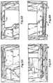
- Fig.5a is a photographic close-up showing particularly the upper portion of the sliding door opening of a van in its originally manufactured configuration with the OEM header 15.
- Fig.5b is a photographic close-up showing a the same van with reduced profile sliding door header 100 of this invention. This shows the increase in vertical height of the doorway made possible by the invention.
- Fig. 6a is a photograph showing the lower portion of a sliding door opening of a van in its originally manufactured configuration with the sill track assembly 19 below the floor 16 and above inner seal 17 and lower seal 18.
- Fig. 6b is a photograph showing a the same van with the newly configured doorway of the invention. This shows the lowered floor 16', sill track 19' installed in a lower position, and a single lower seal 20. Note that the vertical profile from floor to bottom of door opening 21 is greatly reduced. Either the original (OEM) sill track 19' may be used with the single lower seal 20, or a reduced profile sill (as in Fig. 1 but with curved arm 22 being above the plate 4) may be used.
- OEM original
- Fig. 7 is a plan view of a portion of the header plate designated by arrows 7-7 Figure 1 , showing the rear portion of the slide track slot and roller insertion/release hole 6, the outboard margin of the header plate being at the top of the figure. Since the center of mass of the door is generally outboard of the slide track slot 5, the bearing force of the roller assembly 8 is caused to be applied to the outboard face 45 of the slide track slot, preventing the roller from contacting the intersection 27 of the slide track slot 5 and roller insertion/release hole 6 on the inboard edge of the slot 47 during door opening and closing. The minimum dimension of this intersection chord 27 of hole 6 with the inside edge of slot 47 is indicated as "id".
- Fig. 8 is an elevation view in cross-section of the dumbbell roller assembly 8 and roller mounting pin 13 shown mounted, via bolt 23 in the adjustment slot 12 of the floating roller arm 7, pin 13 being internally threaded to receive the threaded portion 23' of bolt 23.
- the outside diameter of the neck or spindle 25 of roller is indicated as "od”.
- the dumbbell roller assembly 8 is of conventional design known in the art. However, with reference to Fig. 7 , the dimension id of the intersection chord 27 on the inside edge 47 of the slide track slot 5 and the roller insertion/release hole 6 is selected to be just slightly less than the outside diameter od 25 of the roller 8, to require a push or snap-in to hole 6, in order to transfer the roller between the roller insertion/release hole 6 and slot 5.
- the diameter D H of the hole 6 is slightly larger than the outer diameter D R of the roller 25.
- the principal embodiment has a horizontal header plate adjacent the top of the door opening having a longitudinal roller guide slot with a straight aft section and a forward section curved inward to guide the door as it slides between an aft open position along the vehicle side and a forward closed position within the door opening.
- the door is supported at its upper portion by a floating or pivoted roller arm which mounts a dumbbell shaped roller engaging the header slot.
- the roller and arm are selectably releasable from the header slot through a hole located in the header plate.
- the release hole intersects the inside edge of an intermediate portion of the guide slot to form a passage between the guide slot and the release hole.
- the engaged center portion of the roller is sized to "snap-fit" or move through this passage upon application of positive force, to facilitate mounting/demounting of the door by insertion/removal of the roller through the release hole.
- the lower portion of the door is supported by a sill incorporating a similarly shape guide slot engaging a roller mounted to an arm assembly which is fixed or optionally restrictedly pivoted, so that the arm supports the vertical forces on the door.
Landscapes
- Engineering & Computer Science (AREA)
- Mechanical Engineering (AREA)
- Support Devices For Sliding Doors (AREA)
Applications Claiming Priority (2)
| Application Number | Priority Date | Filing Date | Title |
|---|---|---|---|
| US91458797A | 1997-08-18 | 1997-08-18 | |
| US914587 | 1997-08-18 |
Publications (1)
| Publication Number | Publication Date |
|---|---|
| EP0897819A2 true EP0897819A2 (fr) | 1999-02-24 |
Family
ID=25434547
Family Applications (1)
| Application Number | Title | Priority Date | Filing Date |
|---|---|---|---|
| EP98115445A Withdrawn EP0897819A2 (fr) | 1997-08-18 | 1998-08-17 | Ensemble traverse supérieure et seuil avec bras à rouleau flottant pour porte de camionnette |
Country Status (4)
| Country | Link |
|---|---|
| US (2) | US6178697B1 (fr) |
| EP (1) | EP0897819A2 (fr) |
| AU (1) | AU749303B2 (fr) |
| CA (1) | CA2245210A1 (fr) |
Families Citing this family (10)
| Publication number | Priority date | Publication date | Assignee | Title |
|---|---|---|---|---|
| US7838115B2 (en) | 1995-04-11 | 2010-11-23 | Magna Mirrors Of America, Inc. | Method for manufacturing an articulatable vehicular window assembly |
| AU2481401A (en) | 1999-07-08 | 2001-02-05 | Aai Corporation | Passenger rail car sliding door with high platform threshold |
| US6539669B1 (en) * | 2000-09-14 | 2003-04-01 | Westinghouse Air Brake Technologies Corporation | Plug door drive system |
| US20080122262A1 (en) | 2006-08-21 | 2008-05-29 | Dura Automotive Systems, Inc. | Multi-Pane Window Assembly With Two-Sided Frame |
| GB2485986A (en) * | 2010-11-30 | 2012-06-06 | Clearview Ind Ltd | Window sash horn |
| US9101519B2 (en) | 2013-02-07 | 2015-08-11 | Dallas Smith Corporation | Leveling ramp for a wheelchair |
| ES2558848B1 (es) * | 2014-08-06 | 2016-08-10 | Kiro Robotics, S.L. | Ventana de guillotina para recintos asepticos |
| US9896871B2 (en) | 2016-02-16 | 2018-02-20 | Vantage Mobility International, Llc | Method of extending opening ranges of vehicle sliding doors |
| US10434849B1 (en) * | 2017-05-09 | 2019-10-08 | Mobility Accessories | Van door assembly |
| CA3142961A1 (fr) | 2019-07-02 | 2021-01-07 | The Braun Corporation | Fonctionnement de porte modifie pour un vehicule motorise |
Family Cites Families (11)
| Publication number | Priority date | Publication date | Assignee | Title |
|---|---|---|---|---|
| US2082541A (en) | 1935-04-22 | 1937-06-01 | Murray Corp | Window support and guiding means |
| DE675924C (de) | 1935-11-29 | 1939-05-20 | Standard Pressed Steel Co | Wagenkastenfensterfuehrung |
| US3879799A (en) * | 1973-05-03 | 1975-04-29 | Hough Mfg Corp | Multidirectional suspension system for operable partitions |
| EP0356373B1 (fr) | 1988-08-19 | 1995-07-05 | Suzuki Motor Corporation | Véhicules pourvus d'une porte coulissante |
| US4991905A (en) | 1988-08-29 | 1991-02-12 | Suzuki Motor Company Limited | Vehicle construction of automobile provided with slide door |
| EP0589096B1 (fr) | 1992-09-24 | 1996-12-27 | O.C.L.A.P. S.R.L. | Equipement pour portes coulissantes-louvoyantes pour véhicules de chemin de fer ou de voie de tramway |
| US5398988A (en) | 1993-11-22 | 1995-03-21 | Chrysler Corporation | Vehicle door assembly |
| US5618080A (en) * | 1993-12-27 | 1997-04-08 | Ford Motor Company | Upper track roller mechanism for sliding door |
| FI1694U1 (fi) * | 1994-08-17 | 1995-01-12 | Alusystems Ky | Svaengbar balkongglaskonstruktion |
| US5893242A (en) * | 1997-11-26 | 1999-04-13 | Perron; Jocelyn | Thermally insulating external window shutter |
| GB2383046A (en) | 2001-12-12 | 2003-06-18 | Imerys Minerals Ltd | Calcium carbonate filler in stretched polyolefin film |
-
1998
- 1998-08-17 EP EP98115445A patent/EP0897819A2/fr not_active Withdrawn
- 1998-08-17 CA CA002245210A patent/CA2245210A1/fr not_active Abandoned
- 1998-08-17 AU AU80764/98A patent/AU749303B2/en not_active Ceased
-
1999
- 1999-10-28 US US09/429,241 patent/US6178697B1/en not_active Expired - Fee Related
- 1999-12-28 US US09/473,507 patent/US6158173A/en not_active Expired - Fee Related
Also Published As
| Publication number | Publication date |
|---|---|
| AU8076498A (en) | 1999-02-25 |
| CA2245210A1 (fr) | 1999-02-18 |
| AU749303B2 (en) | 2002-06-20 |
| US6158173A (en) | 2000-12-12 |
| US6178697B1 (en) | 2001-01-30 |
Similar Documents
| Publication | Publication Date | Title |
|---|---|---|
| US4378043A (en) | Pivoting screen panel for sectional garage door | |
| AU749303B2 (en) | Van door header and sill assemblies having a floating roller arm | |
| US5069001A (en) | Pivotable window sash assembly | |
| US4544198A (en) | Automotive vehicle with front and rear sliding doors | |
| US9296280B2 (en) | Hinged bottom roller assembly and counterbalance mechanism for overhead door | |
| EP0100455B1 (fr) | Structure de guidage pour une automobile à portière coulissante | |
| US6860543B2 (en) | Mechanism for moving a door | |
| US6196617B1 (en) | Rear door structure for a vehicle | |
| US5832980A (en) | Floating pivot sliding and swinging panel construction for doors and the like | |
| US4420906A (en) | Window regulator | |
| US5806917A (en) | Integrated motor vehicle door and chassis | |
| US20230086262A1 (en) | Sliding door with braking system | |
| JP2002510762A (ja) | 主枠およびサッシ被覆部材を備えた屋根窓 | |
| US6851743B2 (en) | Slide mechanism for door and structural member assembly | |
| US20050205220A1 (en) | Method and apparatus for positioning a sectional door relative to an opening | |
| US4609027A (en) | Overhead door | |
| GB2214229A (en) | Window stays | |
| US5784839A (en) | Easy to assemble window | |
| US3230585A (en) | Doors | |
| US12077086B2 (en) | Vehicle access ramp | |
| US6623223B1 (en) | Auto rack deck hinge arrangement | |
| US20070272372A1 (en) | Multi-Fold Door and Window Assemblies | |
| JPH0221292Y2 (fr) | ||
| US11339595B2 (en) | Removable door and hinge system therefor | |
| JP2000303751A (ja) | 鉛直方向折り畳式雨戸 |
Legal Events
| Date | Code | Title | Description |
|---|---|---|---|
| PUAI | Public reference made under article 153(3) epc to a published international application that has entered the european phase |
Free format text: ORIGINAL CODE: 0009012 |
|
| AK | Designated contracting states |
Kind code of ref document: A2 Designated state(s): AT BE CH CY DE DK ES FI FR GB GR IE IT LI LU MC NL PT SE |
|
| AX | Request for extension of the european patent |
Free format text: AL PAYMENT 980817;LT PAYMENT 980817;LV PAYMENT 980817;MK;RO PAYMENT 980817;SI PAYMENT 980817 |
|
| STAA | Information on the status of an ep patent application or granted ep patent |
Free format text: STATUS: THE APPLICATION IS DEEMED TO BE WITHDRAWN |
|
| 18D | Application deemed to be withdrawn |
Effective date: 20030301 |