EP0897825A1 - Véhicule avec pile à combustible - Google Patents
Véhicule avec pile à combustible Download PDFInfo
- Publication number
- EP0897825A1 EP0897825A1 EP98112818A EP98112818A EP0897825A1 EP 0897825 A1 EP0897825 A1 EP 0897825A1 EP 98112818 A EP98112818 A EP 98112818A EP 98112818 A EP98112818 A EP 98112818A EP 0897825 A1 EP0897825 A1 EP 0897825A1
- Authority
- EP
- European Patent Office
- Prior art keywords
- fuel cell
- energy
- braking energy
- cell system
- methanol
- Prior art date
- Legal status (The legal status is an assumption and is not a legal conclusion. Google has not performed a legal analysis and makes no representation as to the accuracy of the status listed.)
- Withdrawn
Links
Images
Classifications
-
- H—ELECTRICITY
- H01—ELECTRIC ELEMENTS
- H01M—PROCESSES OR MEANS, e.g. BATTERIES, FOR THE DIRECT CONVERSION OF CHEMICAL ENERGY INTO ELECTRICAL ENERGY
- H01M8/00—Fuel cells; Manufacture thereof
- H01M8/04—Auxiliary arrangements, e.g. for control of pressure or for circulation of fluids
- H01M8/04082—Arrangements for control of reactant parameters, e.g. pressure or concentration
- H01M8/04089—Arrangements for control of reactant parameters, e.g. pressure or concentration of gaseous reactants
-
- B—PERFORMING OPERATIONS; TRANSPORTING
- B60—VEHICLES IN GENERAL
- B60L—PROPULSION OF ELECTRICALLY-PROPELLED VEHICLES; SUPPLYING ELECTRIC POWER FOR AUXILIARY EQUIPMENT OF ELECTRICALLY-PROPELLED VEHICLES; ELECTRODYNAMIC BRAKE SYSTEMS FOR VEHICLES IN GENERAL; MAGNETIC SUSPENSION OR LEVITATION FOR VEHICLES; MONITORING OPERATING VARIABLES OF ELECTRICALLY-PROPELLED VEHICLES; ELECTRIC SAFETY DEVICES FOR ELECTRICALLY-PROPELLED VEHICLES
- B60L58/00—Methods or circuit arrangements for monitoring or controlling batteries or fuel cells, specially adapted for electric vehicles
- B60L58/30—Methods or circuit arrangements for monitoring or controlling batteries or fuel cells, specially adapted for electric vehicles for monitoring or controlling fuel cells
- B60L58/32—Methods or circuit arrangements for monitoring or controlling batteries or fuel cells, specially adapted for electric vehicles for monitoring or controlling fuel cells for controlling the temperature of fuel cells, e.g. by controlling the electric load
- B60L58/33—Methods or circuit arrangements for monitoring or controlling batteries or fuel cells, specially adapted for electric vehicles for monitoring or controlling fuel cells for controlling the temperature of fuel cells, e.g. by controlling the electric load by cooling
-
- B—PERFORMING OPERATIONS; TRANSPORTING
- B60—VEHICLES IN GENERAL
- B60L—PROPULSION OF ELECTRICALLY-PROPELLED VEHICLES; SUPPLYING ELECTRIC POWER FOR AUXILIARY EQUIPMENT OF ELECTRICALLY-PROPELLED VEHICLES; ELECTRODYNAMIC BRAKE SYSTEMS FOR VEHICLES IN GENERAL; MAGNETIC SUSPENSION OR LEVITATION FOR VEHICLES; MONITORING OPERATING VARIABLES OF ELECTRICALLY-PROPELLED VEHICLES; ELECTRIC SAFETY DEVICES FOR ELECTRICALLY-PROPELLED VEHICLES
- B60L58/00—Methods or circuit arrangements for monitoring or controlling batteries or fuel cells, specially adapted for electric vehicles
- B60L58/30—Methods or circuit arrangements for monitoring or controlling batteries or fuel cells, specially adapted for electric vehicles for monitoring or controlling fuel cells
- B60L58/32—Methods or circuit arrangements for monitoring or controlling batteries or fuel cells, specially adapted for electric vehicles for monitoring or controlling fuel cells for controlling the temperature of fuel cells, e.g. by controlling the electric load
- B60L58/34—Methods or circuit arrangements for monitoring or controlling batteries or fuel cells, specially adapted for electric vehicles for monitoring or controlling fuel cells for controlling the temperature of fuel cells, e.g. by controlling the electric load by heating
-
- B—PERFORMING OPERATIONS; TRANSPORTING
- B60—VEHICLES IN GENERAL
- B60L—PROPULSION OF ELECTRICALLY-PROPELLED VEHICLES; SUPPLYING ELECTRIC POWER FOR AUXILIARY EQUIPMENT OF ELECTRICALLY-PROPELLED VEHICLES; ELECTRODYNAMIC BRAKE SYSTEMS FOR VEHICLES IN GENERAL; MAGNETIC SUSPENSION OR LEVITATION FOR VEHICLES; MONITORING OPERATING VARIABLES OF ELECTRICALLY-PROPELLED VEHICLES; ELECTRIC SAFETY DEVICES FOR ELECTRICALLY-PROPELLED VEHICLES
- B60L7/00—Electrodynamic brake systems for vehicles in general
- B60L7/10—Dynamic electric regenerative braking
-
- H—ELECTRICITY
- H01—ELECTRIC ELEMENTS
- H01M—PROCESSES OR MEANS, e.g. BATTERIES, FOR THE DIRECT CONVERSION OF CHEMICAL ENERGY INTO ELECTRICAL ENERGY
- H01M8/00—Fuel cells; Manufacture thereof
- H01M8/06—Combination of fuel cells with means for production of reactants or for treatment of residues
- H01M8/0606—Combination of fuel cells with means for production of reactants or for treatment of residues with means for production of gaseous reactants
- H01M8/0612—Combination of fuel cells with means for production of reactants or for treatment of residues with means for production of gaseous reactants from carbon-containing material
-
- H—ELECTRICITY
- H01—ELECTRIC ELEMENTS
- H01M—PROCESSES OR MEANS, e.g. BATTERIES, FOR THE DIRECT CONVERSION OF CHEMICAL ENERGY INTO ELECTRICAL ENERGY
- H01M2250/00—Fuel cells for particular applications; Specific features of fuel cell system
- H01M2250/20—Fuel cells in motive systems, e.g. vehicle, ship, plane
-
- H—ELECTRICITY
- H01—ELECTRIC ELEMENTS
- H01M—PROCESSES OR MEANS, e.g. BATTERIES, FOR THE DIRECT CONVERSION OF CHEMICAL ENERGY INTO ELECTRICAL ENERGY
- H01M8/00—Fuel cells; Manufacture thereof
- H01M8/04—Auxiliary arrangements, e.g. for control of pressure or for circulation of fluids
- H01M8/04007—Auxiliary arrangements, e.g. for control of pressure or for circulation of fluids related to heat exchange
- H01M8/04014—Heat exchange using gaseous fluids; Heat exchange by combustion of reactants
- H01M8/04022—Heating by combustion
-
- H—ELECTRICITY
- H01—ELECTRIC ELEMENTS
- H01M—PROCESSES OR MEANS, e.g. BATTERIES, FOR THE DIRECT CONVERSION OF CHEMICAL ENERGY INTO ELECTRICAL ENERGY
- H01M8/00—Fuel cells; Manufacture thereof
- H01M8/04—Auxiliary arrangements, e.g. for control of pressure or for circulation of fluids
- H01M8/04007—Auxiliary arrangements, e.g. for control of pressure or for circulation of fluids related to heat exchange
- H01M8/04029—Heat exchange using liquids
-
- H—ELECTRICITY
- H01—ELECTRIC ELEMENTS
- H01M—PROCESSES OR MEANS, e.g. BATTERIES, FOR THE DIRECT CONVERSION OF CHEMICAL ENERGY INTO ELECTRICAL ENERGY
- H01M8/00—Fuel cells; Manufacture thereof
- H01M8/04—Auxiliary arrangements, e.g. for control of pressure or for circulation of fluids
- H01M8/04082—Arrangements for control of reactant parameters, e.g. pressure or concentration
- H01M8/04089—Arrangements for control of reactant parameters, e.g. pressure or concentration of gaseous reactants
- H01M8/04119—Arrangements for control of reactant parameters, e.g. pressure or concentration of gaseous reactants with simultaneous supply or evacuation of electrolyte; Humidifying or dehumidifying
- H01M8/04156—Arrangements for control of reactant parameters, e.g. pressure or concentration of gaseous reactants with simultaneous supply or evacuation of electrolyte; Humidifying or dehumidifying with product water removal
-
- Y—GENERAL TAGGING OF NEW TECHNOLOGICAL DEVELOPMENTS; GENERAL TAGGING OF CROSS-SECTIONAL TECHNOLOGIES SPANNING OVER SEVERAL SECTIONS OF THE IPC; TECHNICAL SUBJECTS COVERED BY FORMER USPC CROSS-REFERENCE ART COLLECTIONS [XRACs] AND DIGESTS
- Y02—TECHNOLOGIES OR APPLICATIONS FOR MITIGATION OR ADAPTATION AGAINST CLIMATE CHANGE
- Y02E—REDUCTION OF GREENHOUSE GAS [GHG] EMISSIONS, RELATED TO ENERGY GENERATION, TRANSMISSION OR DISTRIBUTION
- Y02E60/00—Enabling technologies; Technologies with a potential or indirect contribution to GHG emissions mitigation
- Y02E60/30—Hydrogen technology
- Y02E60/50—Fuel cells
-
- Y—GENERAL TAGGING OF NEW TECHNOLOGICAL DEVELOPMENTS; GENERAL TAGGING OF CROSS-SECTIONAL TECHNOLOGIES SPANNING OVER SEVERAL SECTIONS OF THE IPC; TECHNICAL SUBJECTS COVERED BY FORMER USPC CROSS-REFERENCE ART COLLECTIONS [XRACs] AND DIGESTS
- Y02—TECHNOLOGIES OR APPLICATIONS FOR MITIGATION OR ADAPTATION AGAINST CLIMATE CHANGE
- Y02T—CLIMATE CHANGE MITIGATION TECHNOLOGIES RELATED TO TRANSPORTATION
- Y02T10/00—Road transport of goods or passengers
- Y02T10/80—Technologies aiming to reduce greenhouse gasses emissions common to all road transportation technologies
- Y02T10/92—Energy efficient charging or discharging systems for batteries, ultracapacitors, supercapacitors or double-layer capacitors specially adapted for vehicles
-
- Y—GENERAL TAGGING OF NEW TECHNOLOGICAL DEVELOPMENTS; GENERAL TAGGING OF CROSS-SECTIONAL TECHNOLOGIES SPANNING OVER SEVERAL SECTIONS OF THE IPC; TECHNICAL SUBJECTS COVERED BY FORMER USPC CROSS-REFERENCE ART COLLECTIONS [XRACs] AND DIGESTS
- Y02—TECHNOLOGIES OR APPLICATIONS FOR MITIGATION OR ADAPTATION AGAINST CLIMATE CHANGE
- Y02T—CLIMATE CHANGE MITIGATION TECHNOLOGIES RELATED TO TRANSPORTATION
- Y02T90/00—Enabling technologies or technologies with a potential or indirect contribution to GHG emissions mitigation
- Y02T90/40—Application of hydrogen technology to transportation, e.g. using fuel cells
Definitions
- the invention relates to a fuel cell vehicle according to the preamble of claim 1.
- Fuel cell vehicles with an electric drive system and a fuel cell system for providing electrical Energy for the drive system is generally known, the electric drive system typically one or more Has electric motors, which are those of the fuel cell system generated electrical energy in driving forces for the vehicle wheels implement.
- the fuel cell system includes known ones Fuel cell vehicles a methanol reforming plant, with which hydrogen to feed the fuel cells is recovered liquid entrained methanol, so that on a large-volume hydrogen storage can be dispensed with.
- a such a fuel cell system is in the published patent application DE 33 45 956 A1.
- Water electrolysis means are provided with which during vehicle operating phases with low or normal load part of the energy generated by the fuel cell system for the electrolysis of Water is used, the resulting hydrogen and Oxygen are stored in a respective pressure accumulator. Then during vehicle operating phases with peak load requirements the stored hydrogen and oxygen to the fuel cells as reaction gases instead of the methanol reformate gas and air supplied in the other operating phases as reaction gases to serve.
- the size of the fuel cell stack can thereby designed for the lower performance requirements during normal operation and still meet top performance requirements.
- the electric is known To set up a drive system for the recovery of braking energy, e.g. an electric machine of the drive system optionally operated as an electric motor and as a generator.
- the electrical machine works as a driving force Electric motor while it works as a generator in braking phases, with the kinetic vehicle energy into electrical energy is converted back.
- the braking energy recovered in this way is stored in an energy storage, e.g. a flywheel storage or a backup battery, cached and is again available as drive energy.
- a hybrid drive this type is in the published patent application DE 41 24 479 A1. It is also known to be the recovered Braking energy of a hybrid drive system optionally not in one Feed accumulator, but directly to feed existing electrical consumers such as lamps, fans or air conditioning compressor, see the published specification DE 41 42 863 A1.
- the one there Fuel cell system includes, among other things, a temperature control fluid circuit to regulate the temperature of there Fuel cell stack. Located in the temperature control fluid circuit there is an electrical resistance with which the temperature control fluid can be heated. The resistance is electrical via a Power bus powered by the fuel cell stack generated electrical energy is fed and to an electric vehicle drive motor via an inverter is coupled. About the one then working as a generator Drive electric motor and the inverter can brake vehicle energy fed back in the power supply bus and to energize the resistance and thus to heat the temperature control fluid be used if and insofar as need for one such heating fluid during a braking phase. To also heat the temperature control fluid e.g.
- the invention is a technical problem of providing a fuel cell vehicle of the type mentioned at the beginning, that has a comparatively high level of energy utilization.
- the invention solves this problem by providing a Fuel cell vehicle with the features of claim 1, 2 or 3.
- this is electrical Drive system set up for braking energy recovery, and Means are provided for direct use of the recovered braking energy in at least one energy consuming Component of the fuel cell system is realized.
- the kinetic vehicle energy goes on Braking is not entirely lost, but can at least partly in an energy-consuming component of the fuel cell system be used, which is the total energy efficiency of the vehicle increased.
- the recovered braking energy is used directly for the fuel cell system is not additional energy storage, e.g. in the form of a buffer or Drive battery, required, which saves weight contributes and a braking energy recovery easily for Systems without drive battery possible.
- the compressor can have an integrated flywheel storage contain the absorbed braking energy, or a pressure accumulator is provided, in which when feeding from recovered braking energy to the compressor compressed gas is temporarily stored.
- braking energy is recovered especially for the temporary storage of hydrogen-containing reformate gas used by a reforming reactor unit Methanol reforming plant is delivered. This is done downstream the reactor unit provided compressor with recovered Operated braking energy, which thereby compresses reformate gas, then in a pressure reservoir provided for this purpose is cached and for operating phases with increased Power requirements are available.
- braking energy is recovered especially in a methanol reformer as part of the Fuel cell system used by an evaporator an excess water / methanol mixture evaporates and the excess water / methanol vapor in a designated Steam storage is temporarily stored between the Evaporator and a downstream reforming reactor unit is arranged.
- a further developed vehicle according to claim 5 is recovered Braking energy for additional heating of an evaporator a methanol reforming plant with which a Methanol / water mixture before being fed into a reforming reactor unit is evaporated.
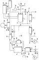
- the single figure shows a block diagram of what is essential to the invention Part of a fuel cell vehicle with a fuel cell system and an electric drive system coupled to it.
- the fuel cell system shown in the figure includes a fuel cell stack 1, the input side via a reformate gas line 2 a hydrogen-rich reformate gas from a Steam reforming of methanol and via an air supply line 3 compressed air can be supplied by a compressor 4 provided by drawing in a fresh air stream 5 becomes.
- An oil cooling circuit 6 with a cooler 7 and a cooling pump 8 serves to cool the fuel cell stack 1.
- the reformate gas is generated in a methanol reforming plant which is part of the fuel cell system and at the heart includes a conventional reforming reactor unit 9.
- An evaporator 10 is connected upstream of the reactor unit 9, liquid methanol from a methanol tank 11 a methanol metering pump 12 and liquid water supplied from a water tank 13 via a water metering pump 14 be and the evaporation of these components Water / methanol vapor mixture is generated via a mixture supply line 15 can be fed into the reactor unit 9 can.
- the reformate gas emerging from the reactor unit 9, the a proportion of carbon monoxide that is harmful to the fuel cells can be supplied to a CO oxidation stage 16, which exothermically oxidizes the carbon monoxide to carbon dioxide.
- the oxygen required for this is a first Part of the cathode exhaust gas stream 17 from the fuel cell stack 1 fed into the CO oxidation state 16, wherein for Quantity control a metering pump 18 is provided.
- a second Part of the cathode exhaust gas stream 17 is used as a heat transfer medium passed through the CO oxidation state 16 and takes the Oxidation heat, for which the CO oxidation state 16 a suitable Has heat exchanger structure.
- a third part of the cathode exhaust flow 17 is passed through a capacitor 19, the on the other hand is acted upon by a cooling air flow 20, which then also serves as a cooling medium for the cooler 7.
- Condenser 19 condenses that in the supplied cathode exhaust gas contained water, which then via a condensate line 21 in the Water tank 12 is returned. That cooled in the condenser 19 Cathode exhaust gas is given off as exhaust air.
- the one heated in the CO oxidation state 16 with the heat of oxidation Part of the cathode exhaust is through a cathode exhaust feed line 22 fed to a catalytic heater 23, the on the other hand, via an anode exhaust gas feed line 24, the anode exhaust gas flow is supplied from the fuel cell stack 1.
- a catalytic heater 23 is under the action of an appropriate one Catalyst material is a catalytic combustion process the anode exhaust gas component with that at the CO oxidation state 16 heated cathode exhaust component performed.
- the heater 23 has a heat exchanger structure and forms part of one Oil heating circuit 25 for heating the reforming reactor unit 9.
- the oil in the heater 23 by the heat of combustion of the catalytic combustion process and heated by a circulation pump 26 of the reforming reactor unit 9 fed to this to carry out the reforming reaction heat the appropriate temperature.
- the reactor unit 9 in a conventional manner Heat exchanger structure in which one or more of the heat oil flowed through heating channels through thermally conductive walls of one one or more parts, filled with suitable catalyst material Reaction space are separated. That from the reactor unit 9 escaping, cooled heating oil then circulates back into the Heater 23 back.
- the evaporator 10 has for this purpose again a heat exchanger structure with separate, in thermal contact standing flow channels for the hot combustion gas on the one hand and the water / methanol mixture on the other.
- the branch line 30 is located on the supply side Compressor 31 for compressing reformate gas to be stored temporarily and a controllable valve 32 on the discharge side, via which temporarily stored, compressed reformate gas from the pressure accumulator 29 metered fed back into the reformate gas line 2 can be.
- a controllable valve 32 on the discharge side, via which temporarily stored, compressed reformate gas from the pressure accumulator 29 metered fed back into the reformate gas line 2 can be.
- the fresh air compressor can be used for this intermediate compressed air storage an integrated flywheel storage for intermediate energy storage include.
- the fuel cell system is controlled by a central system control 35 controlled, hereinafter only related to the with the braking energy recovery implemented in the present vehicle relevant control measures are taken, while the control is otherwise in a conventional manner takes place, the associated also for the sake of clarity Control lines are omitted.
- the system control is used in particular 35 also as an interface between the fuel cell stack 1 and a conventional electric drive system 36, the one or more, on the drive wheels of the vehicle has acting electric motors.
- the drive electric motors during the active drive phases of the fuel stack 1 generated electrical energy is fed through corresponding electrical connecting lines 37, 38 from the fuel cell stack 1 the system control 35 and from there the electrical Drive system 36 is supplied.
- the mode of operation of the vehicle during is now characteristic Braking phases in which kinetic vehicle energy is recovered and directly in one or more energy-consuming components of the fuel cell system is used. That’s it electric drive system 36 set up for braking energy recovery, like this e.g. of hybrid drives is known. Specifically this can be realized in that as a drive electric motor an electrical machine is used which during Braking phases acts as a generator and in this way via the corresponding connecting line 38 electrical energy in the Control Panel 35 feeds back.
- the system controller 35 conducts the regenerative braking energy directly determined energy consuming Components of the fuel cell system for use, without this energy in a separate backup battery or the like must be cached. For this direct Use of recovered braking energy exists in the present Fuel cell system has several options, each of which one or more of the system controller 35 depending on the system state be taken.
- a first option is the reforming reactor unit 9 additionally heat up with regenerated braking energy and thereby their temperature for performing the endothermic Increase methanol reforming reaction, e.g. from approx. 250 ° C to approx. 300 ° C.
- this cannot be done using a Direct electrical heating of the reactor unit 9 shown or in that the system controller 35 an the oil heating circuit 25 assigned, electrical heating element 39 and operates the circulation pump 26 with the regenerated braking energy. Due to the heat capacity of the reactor unit 9, this can directly absorb the recovered braking energy, whereby the increased reactor temperature favors methanol conversion. This also works when the oil heating circuit 25 is heated Thermal oil as a thermal buffer.
- control panel 35 with additional braking energy of the evaporator 10 for example on the evaporator 10 an additional electrical heater 40 can be provided.
- an oil heating circuit may be provided, the heat capacity then in addition to that of the evaporator 10 as thermal Buffer acts.
- the heating of the evaporator 10 can e.g. from approx. 200 ° C to approx. 250 ° C.
- the system control initiates 35 the evaporation of the evaporator 10 supplied Water / methanol mixture in excess and storing the excess water / methanol vapor provided in the water / methanol vapor storage 27.
- the associated valve 28 can then after the braking process the temporarily stored steam successively into the reactor unit 9 can be initiated.
- a fourth possibility of using the regenerated braking energy in the fuel cell system is that the system control 35 the fresh air compressor 4 with regenerated braking energy operates and the additionally provided, compressed Air under high pressure in the compressed air storage 33 temporarily. This can then be carried out successively after the braking process has ended by appropriate control of the associated valve 34 in the fuel cell stack 1 are initiated. If the compressor 4 has an integrated flywheel memory, it can additionally or alternatively generate additional ones Compressed air to absorb the braking energy supplied to the compressor 4.
- a fifth possible use for recovered braking energy in the fuel cell system is that the system control 35 the reformate gas compressor 31 with regenerated braking energy operates, whereby compressed, essentially from hydrogen existing reformate gas under increased pressure in the reformate gas pressure accumulator 29 is cached. This can then be done the braking process is successively returned to the reformate gas line 2 and thus fed into the fuel cell stack 1 become.
Landscapes
- Engineering & Computer Science (AREA)
- Sustainable Energy (AREA)
- Life Sciences & Earth Sciences (AREA)
- Sustainable Development (AREA)
- Power Engineering (AREA)
- Transportation (AREA)
- Mechanical Engineering (AREA)
- Chemical & Material Sciences (AREA)
- Chemical Kinetics & Catalysis (AREA)
- Electrochemistry (AREA)
- General Chemical & Material Sciences (AREA)
- Manufacturing & Machinery (AREA)
- Fuel Cell (AREA)
- Electric Propulsion And Braking For Vehicles (AREA)
Applications Claiming Priority (2)
| Application Number | Priority Date | Filing Date | Title |
|---|---|---|---|
| DE19731642A DE19731642C1 (de) | 1997-07-23 | 1997-07-23 | Brennstoffzellenfahrzeug |
| DE19731642 | 1997-07-23 |
Publications (1)
| Publication Number | Publication Date |
|---|---|
| EP0897825A1 true EP0897825A1 (fr) | 1999-02-24 |
Family
ID=7836637
Family Applications (1)
| Application Number | Title | Priority Date | Filing Date |
|---|---|---|---|
| EP98112818A Withdrawn EP0897825A1 (fr) | 1997-07-23 | 1998-07-10 | Véhicule avec pile à combustible |
Country Status (3)
| Country | Link |
|---|---|
| US (1) | US6408966B1 (fr) |
| EP (1) | EP0897825A1 (fr) |
| DE (1) | DE19731642C1 (fr) |
Cited By (2)
| Publication number | Priority date | Publication date | Assignee | Title |
|---|---|---|---|---|
| EP1056147A3 (fr) * | 1999-05-22 | 2001-08-08 | DaimlerChrysler AG | Système de pile à combustible et méthode pour l'alimentation électrique d'un véhicule |
| WO2014056660A1 (fr) * | 2012-10-12 | 2014-04-17 | Robert Bosch Gmbh | Système de piles à combustible à base de piles à combustible à oxyde solide |
Families Citing this family (69)
| Publication number | Priority date | Publication date | Assignee | Title |
|---|---|---|---|---|
| DE19902051C2 (de) * | 1999-01-20 | 2001-07-19 | Daimler Chrysler Ag | Stromversorgungssystem für ein Fahrzeug |
| NL1013474C2 (nl) * | 1999-05-27 | 2000-12-01 | Plug Power Inc | Systeem voor het genereren van elektrische energie en warmte. |
| US7038766B2 (en) * | 1999-04-01 | 2006-05-02 | Microtrace, Llc | Identification particles and system and method for retrospective identification using spectral codes |
| US6892840B2 (en) * | 1999-05-05 | 2005-05-17 | Daniel J. Meaney, Jr. | Hybrid electric vehicle having alternate power sources |
| US20080264704A1 (en) * | 1999-05-05 | 2008-10-30 | Meaney Daniel J | Hybrid electric vehicle having alternate power sources |
| US6536547B1 (en) * | 1999-05-05 | 2003-03-25 | Daniel J. Meaney, Jr. | Hybrid electric vehicle having alternate power sources |
| DE10008823B4 (de) * | 2000-02-25 | 2006-08-17 | Nucellsys Gmbh | Brennstoffzellensystem und Verfahren zum Betrieb eines Brennstoffzellensystems |
| DE10013660A1 (de) * | 2000-03-20 | 2001-09-27 | Volkswagen Ag | Fahrzeug mit einer Brennstoffzelle |
| DE10015657A1 (de) * | 2000-03-29 | 2001-10-18 | Xcellsis Gmbh | Reformierungsvorrichtung |
| DE10031928A1 (de) * | 2000-06-30 | 2002-01-24 | Daimler Chrysler Ag | Oberleitungsbus |
| DE10047200A1 (de) * | 2000-09-23 | 2002-08-29 | Xcellsis Gmbh | Startvorrichtung für mobile Brennstoffzellensysteme |
| RU2198103C2 (ru) * | 2001-01-09 | 2003-02-10 | Кузнецов Геннадий Петрович | Автономное транспортное средство с рациональным использованием электроэнергии, вырабатываемой в процессе рекуперативного торможения |
| DE10139608B4 (de) * | 2001-08-11 | 2007-05-16 | Nucellsys Gmbh | Brennstoffzellenanlage mit einem Gaserzeugungssystem und einem Brennstoffzellensystem und deren Verwendung |
| US6571897B2 (en) * | 2001-08-13 | 2003-06-03 | Ballard Power Systems Ag | Vehicle with a fuel cell system and method for operating the same |
| US6488345B1 (en) | 2001-08-16 | 2002-12-03 | General Motors Corporation | Regenerative braking system for a batteriless fuel cell vehicle |
| US6968918B2 (en) | 2001-08-23 | 2005-11-29 | General Motors Corporation | Vehicle chassis having programmable operating characteristics and method for using same |
| US6986401B2 (en) | 2001-08-23 | 2006-01-17 | General Motors Corporation | Systems packaged within flat vehicle chassis |
| US6830117B2 (en) | 2001-08-23 | 2004-12-14 | General Motors Corporation | Vehicle chassis having systems responsive to non-mechanical control signals |
| US6938712B2 (en) | 2001-08-23 | 2005-09-06 | General Motors Corporation | Fuel cell powered chassis mobile electrical source and method of use thereof |
| US6976307B2 (en) | 2001-08-23 | 2005-12-20 | General Motors Corporation | Accelerated vehicle development process |
| US7000318B2 (en) * | 2001-08-23 | 2006-02-21 | General Motors Corporation | Method of designing and manufacturing vehicles |
| US20030040979A1 (en) * | 2001-08-23 | 2003-02-27 | Borroni-Bird Christopher E. | Methods of conducting vehicle business transactions |
| US6880856B2 (en) | 2001-08-23 | 2005-04-19 | General Motors Corporation | Vehicle body configurations |
| US6845839B2 (en) | 2001-08-23 | 2005-01-25 | General Motors Corporation | Vehicle body platform |
| US20030037982A1 (en) * | 2001-08-23 | 2003-02-27 | Chernoff Adrian B. | Vehicle chassis having programmable operating characteristics and method for using same |
| US6959475B2 (en) * | 2001-08-23 | 2005-11-01 | General Motors Corporation | Vehicle body business methods |
| US7373315B2 (en) * | 2001-08-23 | 2008-05-13 | General Motors Corporation | Vehicle body business methods |
| US6726438B2 (en) | 2001-08-23 | 2004-04-27 | General Motors Corporation | Chassis stacking |
| US6836943B2 (en) * | 2001-08-23 | 2005-01-04 | General Motors Corporation | Vehicle body manufacturing process |
| US7275609B2 (en) | 2001-08-23 | 2007-10-02 | General Motors Corporation | Vehicle body connection system |
| US6843336B2 (en) | 2001-08-23 | 2005-01-18 | General Motors Corporation | Vehicle belly pan |
| US20030094319A1 (en) * | 2001-08-23 | 2003-05-22 | Chernoff Adrian B. | Vehicle body interchangeability |
| US6889785B2 (en) * | 2001-08-23 | 2005-05-10 | General Motors Corporation | Vehicle chassis having systems responsive to non-mechanical control signals |
| US6766873B2 (en) | 2001-08-23 | 2004-07-27 | General Motors Corporation | Fuel cell vehicle with by-wire technology |
| US7360816B2 (en) | 2001-08-23 | 2008-04-22 | General Motors Corporation | Vehicle development process characterized by market responsiveness |
| US7292992B2 (en) * | 2001-08-23 | 2007-11-06 | General Motors Corporation | Methods of conducting vehicle business transactions |
| US7083016B2 (en) | 2001-08-23 | 2006-08-01 | General Motors Corporation | Mobile chassis and interchangeable vehicle body with waste heat rejection system |
| US6712164B2 (en) * | 2001-08-23 | 2004-03-30 | General Motors Corporation | Vehicle having systems responsive to non-mechanical control signals |
| US7028791B2 (en) | 2001-08-23 | 2006-04-18 | General Motors Corporation | Mobile chassis and interchangeable vehicle body with a heating, ventilation and air conditioning system |
| DE10147367A1 (de) * | 2001-09-26 | 2003-04-17 | Ballard Power Systems | Brennstoffzellenbetriebseinrichtung |
| DE10148113A1 (de) * | 2001-09-28 | 2003-04-30 | Daimler Chrysler Ag | Fahrzeug mit einem Energiespeicher und Verfahren zum Betreiben des Fahrzeugs |
| DE10148854B4 (de) * | 2001-10-04 | 2009-02-26 | Robert Bosch Gmbh | Kraft-Wärme-Anlage und Verfahren zur Erzeugung von elektrischer und thermischer Energie |
| DE10154637B4 (de) * | 2001-11-07 | 2009-08-20 | Robert Bosch Gmbh | Brennstoffbereitstellungseinheit und deren Verwendung zur Bereitstellung eines wasserstoffhaltigen Brennstoffs |
| US7441615B2 (en) | 2001-12-07 | 2008-10-28 | General Motors Corporation | Modular chassis with simplified body-attachment interface |
| US6971471B2 (en) | 2001-12-07 | 2005-12-06 | General Motors Corporation | Multi-directional drive |
| DE10212872A1 (de) * | 2002-03-22 | 2003-10-02 | Volkswagen Ag | Verfahren zum einstellbaren Kühlen eines Betriebsmediumstroms in einem Wärmetauscher, entsprechender Wärmetauscher und entsprechendes Brennstoffzellensystem |
| US6923282B2 (en) | 2002-10-01 | 2005-08-02 | General Motors Corporation | Chassis subassembly module and method for using same |
| US7303033B2 (en) | 2002-10-10 | 2007-12-04 | General Motors Corporation | Vehicle frame assembly and method for same |
| US6935658B2 (en) * | 2002-10-15 | 2005-08-30 | General Motors Corporation | Chassis frame module and method of use for same |
| US20040149500A1 (en) * | 2003-02-05 | 2004-08-05 | Chernoff Adrian B. | Pre-engineered frame portion and method of use therefor |
| US6899194B2 (en) | 2003-02-26 | 2005-05-31 | General Motors Corporation | Lower vehicle body structure and method of use therefor |
| US6819286B2 (en) * | 2003-02-28 | 2004-11-16 | Motorola, Inc. | Location determination for mobile units |
| US6948226B2 (en) * | 2003-04-02 | 2005-09-27 | General Motors Corporation | Chassis frame packaging cavity loading method |
| US20040194280A1 (en) * | 2003-04-07 | 2004-10-07 | Borroni-Bird Christopher E. | Rolling chassis and assembled bodies |
| US7132191B2 (en) * | 2003-09-17 | 2006-11-07 | General Motors Corporation | Addressing one MEA failure mode by controlling MEA catalyst layer overlap |
| US20060242906A1 (en) * | 2005-04-28 | 2006-11-02 | Macbain John A | Reformer system and method of operating the same |
| JP2008269841A (ja) * | 2007-04-17 | 2008-11-06 | Toyota Motor Corp | 燃料電池システム |
| DE102008011235A1 (de) * | 2008-02-26 | 2009-08-27 | Dbk David + Baader Gmbh | Temperaturregelanlage für Brennstoffzellen und Verfahren zur Temperaturregelung von Brennstoffzellen |
| US20100025125A1 (en) * | 2008-08-01 | 2010-02-04 | Daimler Ag | Method and Apparatus for the Operation of a Vehicle |
| US8347829B2 (en) * | 2009-06-02 | 2013-01-08 | James Harper | Electrolytic reactor and related methods for supplementing the air intake of an internal combustion engine |
| WO2011007430A1 (fr) * | 2009-07-15 | 2011-01-20 | 三菱電機株式会社 | Dispositif de commande de propulsion dune voiture électrique |
| RU2445219C1 (ru) * | 2010-11-17 | 2012-03-20 | Государственное образовательное учреждение высшего профессионального образования "Самарский государственный университет путей сообщения" (СамГУПС) | Способ работы маневрового локомотива и маневровый локомотив |
| RU2453448C1 (ru) * | 2010-12-27 | 2012-06-20 | Государственное образовательное учреждение высшего профессионального образования "Самарский государственный университет путей сообщения" (СамГУПС) | Способ работы маневрового локомотива и маневровый локомотив |
| DE102013203890A1 (de) | 2013-03-07 | 2014-09-11 | Bayerische Motoren Werke Aktiengesellschaft | Brennstoffzellensystem mit einer Sauerstoffanreicherungsvorrichtung |
| WO2017164471A1 (fr) * | 2016-03-24 | 2017-09-28 | 에스퓨얼셀(주) | Système de pile à combustible et procédé permettant de le piloter |
| DE102016213763A1 (de) | 2016-07-27 | 2018-02-01 | Ford Global Technologies, Llc | Kraftfahrzeug mit einem Verbrennungsmotor und einer elektrischen Bremsenergierückgewinnungseinrichtung und Verfahren zum Betrieb des Kraftfahrzeugs |
| KR102703744B1 (ko) * | 2019-07-30 | 2024-09-09 | 현대자동차주식회사 | 연료전지 차량용 냉각 시스템 |
| CN112537218B (zh) * | 2020-11-26 | 2022-07-12 | 哈尔滨工业大学 | 一种基于制冷循环的低温储氢技术的燃料电池充电系统 |
| EP4283728A1 (fr) * | 2022-05-25 | 2023-11-29 | KNORR-BREMSE Systeme für Nutzfahrzeuge GmbH | Système de palier à gaz, utilisation de moyens de palier à gaz dans un système de pile à combustible, système de pile à combustible, agencement de systèmes avec des consommateurs de gaz sous pression et véhicule |
Citations (5)
| Publication number | Priority date | Publication date | Assignee | Title |
|---|---|---|---|---|
| JPH06203846A (ja) * | 1992-12-28 | 1994-07-22 | Honda Motor Co Ltd | 回生制動による反応ガス圧縮システム |
| US5346778A (en) * | 1992-08-13 | 1994-09-13 | Energy Partners, Inc. | Electrochemical load management system for transportation applications |
| JPH0799057A (ja) * | 1993-09-28 | 1995-04-11 | Toyota Central Res & Dev Lab Inc | 燃料電池と冷房装置のコンバインシステム |
| EP0755088A2 (fr) * | 1995-07-21 | 1997-01-22 | Railway Technical Research Institute | Système de puissance régénérable |
| US5678410A (en) * | 1993-08-06 | 1997-10-21 | Toyota Jidosha Kabushiki Kaisha | Combined system of fuel cell and air-conditioning apparatus |
Family Cites Families (15)
| Publication number | Priority date | Publication date | Assignee | Title |
|---|---|---|---|---|
| US4084924A (en) * | 1977-02-25 | 1978-04-18 | Alexander Ivanoff | Pump-motor assemblage for circulating a coolant |
| US4657829A (en) * | 1982-12-27 | 1987-04-14 | United Technologies Corporation | Fuel cell power supply with oxidant and fuel gas switching |
| US4760697A (en) * | 1986-08-13 | 1988-08-02 | National Research Council Of Canada | Mechanical power regeneration system |
| US4836755A (en) * | 1988-03-22 | 1989-06-06 | Durr Dental Gmbh & Co Kg | Compressor with balanced flywheel |
| DE4124479C2 (de) * | 1991-07-24 | 2002-05-16 | Bayerische Motoren Werke Ag | Hybridantrieb, insbesondere für Fahrzeuge |
| DE4142863C2 (de) * | 1991-10-16 | 1996-03-07 | Mannesmann Ag | Bremseinrichtung für ein nicht-spurgebundenes Fahrzeug |
| US5228529A (en) * | 1991-12-17 | 1993-07-20 | Stuart Rosner | Method for renewing fuel cells using magnesium anodes |
| JP3687991B2 (ja) * | 1994-02-24 | 2005-08-24 | 株式会社エクォス・リサーチ | ハイブリッド電源装置 |
| JP3515619B2 (ja) * | 1994-11-30 | 2004-04-05 | 株式会社日立製作所 | 電気車の駆動装置及び駆動制御方法 |
| US5823280A (en) * | 1995-01-12 | 1998-10-20 | Nevcor, Inc. | Hybrid parallel electric vehicle |
| WO1996041393A1 (fr) * | 1995-06-07 | 1996-12-19 | Ballard Power Systems Inc. | Systeme de regulation de temperature pour un vehicule a piles a combustible |
| US5771476A (en) * | 1995-12-29 | 1998-06-23 | Dbb Fuel Cell Engines Gmbh | Power control system for a fuel cell powered vehicle |
| FR2743342B1 (fr) * | 1996-01-05 | 1998-02-13 | Smh Management Services Ag | Procede et dispositif pour regler la repartition de la puissance electrique dans un vehicule automobile, notamment la propulsion hybride |
| US5925993A (en) * | 1996-05-02 | 1999-07-20 | Chrysler Corporation | Power control architecture for a hybrid power source |
| JP4049833B2 (ja) * | 1996-07-26 | 2008-02-20 | トヨタ自動車株式会社 | 電源装置および電気自動車 |
-
1997
- 1997-07-23 DE DE19731642A patent/DE19731642C1/de not_active Expired - Fee Related
-
1998
- 1998-07-10 EP EP98112818A patent/EP0897825A1/fr not_active Withdrawn
- 1998-07-23 US US09/120,801 patent/US6408966B1/en not_active Expired - Fee Related
Patent Citations (5)
| Publication number | Priority date | Publication date | Assignee | Title |
|---|---|---|---|---|
| US5346778A (en) * | 1992-08-13 | 1994-09-13 | Energy Partners, Inc. | Electrochemical load management system for transportation applications |
| JPH06203846A (ja) * | 1992-12-28 | 1994-07-22 | Honda Motor Co Ltd | 回生制動による反応ガス圧縮システム |
| US5678410A (en) * | 1993-08-06 | 1997-10-21 | Toyota Jidosha Kabushiki Kaisha | Combined system of fuel cell and air-conditioning apparatus |
| JPH0799057A (ja) * | 1993-09-28 | 1995-04-11 | Toyota Central Res & Dev Lab Inc | 燃料電池と冷房装置のコンバインシステム |
| EP0755088A2 (fr) * | 1995-07-21 | 1997-01-22 | Railway Technical Research Institute | Système de puissance régénérable |
Non-Patent Citations (2)
| Title |
|---|
| PATENT ABSTRACTS OF JAPAN vol. 018, no. 551 (E - 1619) 20 October 1994 (1994-10-20) * |
| PATENT ABSTRACTS OF JAPAN vol. 095, no. 007 31 August 1995 (1995-08-31) * |
Cited By (3)
| Publication number | Priority date | Publication date | Assignee | Title |
|---|---|---|---|---|
| EP1056147A3 (fr) * | 1999-05-22 | 2001-08-08 | DaimlerChrysler AG | Système de pile à combustible et méthode pour l'alimentation électrique d'un véhicule |
| US6472091B1 (en) | 1999-05-22 | 2002-10-29 | Daimlerchrysler Ag | Fuel cell system and method for supplying electric power in a motor vehicle |
| WO2014056660A1 (fr) * | 2012-10-12 | 2014-04-17 | Robert Bosch Gmbh | Système de piles à combustible à base de piles à combustible à oxyde solide |
Also Published As
| Publication number | Publication date |
|---|---|
| US6408966B1 (en) | 2002-06-25 |
| DE19731642C1 (de) | 1999-02-18 |
Similar Documents
| Publication | Publication Date | Title |
|---|---|---|
| DE19731642C1 (de) | Brennstoffzellenfahrzeug | |
| EP0859421B1 (fr) | Système de piles à combustible liquide | |
| EP3639314B1 (fr) | Dispositif et procédé de production du courant électrique au moyen d'hydrogène et d'un milieu d'accumulation d'hydrogène | |
| DE102004016375B4 (de) | Brennstoffzellensystem mit Kühlkanälen sowie Verfahren zum Betrieb eines Brennstoffzellensystems mit Kühlkanälen | |
| DE112005001327T5 (de) | Kühlvorrichtung für Brennstoffzellen und mit einer solchen Kühlvorrichtung ausgestattetes Motorkraftfahrzeug | |
| EP1226617A2 (fr) | Dispositif a piles a combustibles et procede de fonctionnement correspondant | |
| DE10152809A1 (de) | Hybridantriebssystem | |
| WO2007124946A2 (fr) | Système utilisateur d'hydrogène et procédé permettant de le faire fonctionner | |
| DE10154637B4 (de) | Brennstoffbereitstellungseinheit und deren Verwendung zur Bereitstellung eines wasserstoffhaltigen Brennstoffs | |
| DE10317123B4 (de) | Vorrichtung und Verfahren zum Brennstoffzellenkaltstart mit Metallhydriden und deren Verwendung | |
| DE112004001828T5 (de) | Metallhydridheizelement | |
| DE102010013000A1 (de) | Verfahren zum Betreiben eines elektrischen Energieerzeugungssystems in einem Fahrzeug | |
| EP4543801A1 (fr) | Dispositif et procédé pour fournir de l'énergie électrique au moyen d'un milieu porteur d'hydrogène et plate-forme mobile dotée d'un tel dispositif | |
| WO2002019789A2 (fr) | Dispositif a pile a combustible et procede pour faire fonctionner un tel dispositif | |
| EP1032066B1 (fr) | Système de piles à combustible | |
| DE102019133092A1 (de) | Verfahren zum Betreiben eines Kraftfahrzeugs sowie Kraftfahrzeug | |
| EP1178552A2 (fr) | Système de pile à combustible | |
| DE102016204097A1 (de) | Batteriesystem, Verfahren zum Betrieb eines Batteriesystems und Kraftfahrzeug | |
| EP1106569B1 (fr) | Vaporisateur pour un système de piles à combustible | |
| DE102018209430A1 (de) | Verfahren zur Abgabe von Wärme, Brennstoffzellensystem und Brennstoffzellenfahrzeug | |
| EP1273062A2 (fr) | Systeme de piles a combustible | |
| DE102019211876A1 (de) | Leistungsanordnung und Verfahren zu deren Betrieb | |
| EP1359312A2 (fr) | Véhicule automobile ayant un dispositif d'entraínement et un dispositif de stockage pour un fluide de travail | |
| DE10025667B4 (de) | Verfahren zum Betreiben einer Gaserzeugungsvorrichtung in einem Brennstoffzellensystem | |
| DE19636068C2 (de) | Vorrichtung und Verfahren zur Wasserstoff- und/oder Synthesegasgewinnung |
Legal Events
| Date | Code | Title | Description |
|---|---|---|---|
| PUAI | Public reference made under article 153(3) epc to a published international application that has entered the european phase |
Free format text: ORIGINAL CODE: 0009012 |
|
| AK | Designated contracting states |
Kind code of ref document: A1 Designated state(s): DE FR GB IT |
|
| AX | Request for extension of the european patent |
Free format text: AL;LT;LV;MK;RO;SI |
|
| 17P | Request for examination filed |
Effective date: 19990218 |
|
| AKX | Designation fees paid |
Free format text: DE FR GB IT |
|
| RAP1 | Party data changed (applicant data changed or rights of an application transferred) |
Owner name: XCELLSIS GMBH |
|
| RAP1 | Party data changed (applicant data changed or rights of an application transferred) |
Owner name: BALLARD POWER SYSTEMS AG |
|
| RAP1 | Party data changed (applicant data changed or rights of an application transferred) |
Owner name: NUCELLSYS GMBH |
|
| 17Q | First examination report despatched |
Effective date: 20071106 |
|
| STAA | Information on the status of an ep patent application or granted ep patent |
Free format text: STATUS: THE APPLICATION HAS BEEN WITHDRAWN |
|
| 18W | Application withdrawn |
Effective date: 20090921 |