EP0897826A2 - Machine d'installation de ligne catenaire - Google Patents
Machine d'installation de ligne catenaire Download PDFInfo
- Publication number
- EP0897826A2 EP0897826A2 EP98890205A EP98890205A EP0897826A2 EP 0897826 A2 EP0897826 A2 EP 0897826A2 EP 98890205 A EP98890205 A EP 98890205A EP 98890205 A EP98890205 A EP 98890205A EP 0897826 A2 EP0897826 A2 EP 0897826A2
- Authority
- EP
- European Patent Office
- Prior art keywords
- guide
- transverse
- machine
- machine according
- drive
- Prior art date
- Legal status (The legal status is an assumption and is not a legal conclusion. Google has not performed a legal analysis and makes no representation as to the accuracy of the status listed.)
- Granted
Links
Images


Classifications
-
- B—PERFORMING OPERATIONS; TRANSPORTING
- B60—VEHICLES IN GENERAL
- B60M—POWER SUPPLY LINES, AND DEVICES ALONG RAILS, FOR ELECTRICALLY- PROPELLED VEHICLES
- B60M1/00—Power supply lines for contact with collector on vehicle
- B60M1/12—Trolley lines; Accessories therefor
- B60M1/28—Manufacturing or repairing trolley lines
Definitions
- the invention relates to a machine for laying a contact wire and / or a suspension cable of an overhead line of a track, with one Rail chassis supported machine frame, on which one - wound Contact wire or carrying rope containing - wire drum and a guide device with one arranged on a mast, via a drive Height-adjustable guide roller for guiding the wire drum unwound contact wire or suspension cables are stored, the Guide device based on a swivel drive around a machine in the longitudinal direction extending axis is pivotally mounted.
- Such a machine is already known from EP 0 776 780 A1, with of a contact wire or a suspension cable of a catenary in one Operation with the final tension can be laid.
- the guide device consists of a Drive telescopic extendable mast, at its upper end a groove-provided, freely rotatable guide roller is arranged.
- the mast and the wire drum are together with the tension device mounted on a swivel frame that is horizontal, in Machine longitudinal axis pivotable by means of a drive is.
- the guide device has the shape of a height-adjustable Jib crane that rotates on a vertical axis on the Machine frame is set up and the two guide rollers at its free end are arranged to guide the contact wire or suspension cable.
- the fork-like bracket of each guide roller is movable with a support arm connected to an individual rotation of the guide rollers by one axis running approximately in the longitudinal direction of the track in the course of the required to allow lateral pivoting of the crane.
- AT-B-398 737 Another machine known from AT-B-398 737 is with two wire drums equipped for suspension cable and contact wire, each with its own, independent management is assigned.
- the latter have the Form of height-adjustable boom arms that can be swiveled to the side the machine frame are mounted and a device at the free end for guiding and clamping the wire.
- DE-A-20 12 248 describes a machine for overhead line assembly with a management facility, each with a management role for Includes contact wire and suspension cable. These two are stacked Guide rollers are attached to the machine frame using one Device telescopic in both vertical and horizontal directions adjustable.
- the object of the present invention is now to create a Machine of the generic type with the most varied of operating conditions unimpeded, precise laying of the catenary possible is.
- this object is described with the above Machine solved in that the guide roller using a transverse adjustment drive in a normal to the longitudinal direction of the mast and transverse to Machine longitudinal axis direction adjustable relative to the mast is trained.
- This inventive design of the guide device enables in advantageously a further transverse adjustment of the guide roller in addition for maximum transverse swiveling based on the swivel drive.
- the adjustment range of the guide device in Track cross direction enlarged and so an even more precise positioning of the Contact wire favors.
- the relative adjustment is particularly advantageous between the guide roller and the mast, but when laying the suspension cable, its continuous guidance in the longitudinal direction of the track changes due to its Can make problematic location above the cantilever arm.
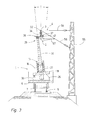
- the machine 1 and 2 is a machine 1 for laying a contact wire 2 or a suspension cable 3 of a catenary or overhead line 4 of a track 5 is shown.
- the machine 1 has a machine frame 6 which has two Rail bogies 7 supported on the track 5 and with each end a coupling 8 for incorporation into a train set and with a Driving or working cabin 9 and a height and side pivoting Crane 10 is equipped.
- a motor 11 and a hydraulic unit 12 are for the energy supply of a travel drive 13 of the machine 1 and all others, Provided drives to be described, based on control devices 14 can be remote controlled.
- the contact wire 2 to be laid or the supporting cable 3 is on a wire drum 15 wound around a horizontal in the cross-machine direction
- Rotation axis 16 is rotatably mounted on a carriage 17.
- This is in turn mounted on a swivel frame 18 and relative to it displaceable in the cross-machine direction by means of drives 19.
- a tension device on the swivel frame 18 20 provided, consisting of two of the wire drum 15 in Deflected deflection rollers 21 is formed in the longitudinal direction of the machine. This are rotatable about axes 22 parallel to the axis of rotation 16 and with a Brake disc 23 and a braking device 24 acting on it.
- the pulleys are used to maintain a constant tension 21 can be acted upon by a hydraulic motor 25.
- the swivel frame 18 in the area between the cabin 9 and the crane 10 with the machine frame 6 connected via two supports 26 and on this by one in Horizontal axis 27 extending in the machine longitudinal direction can be pivoted stored.
- the axis 27 is formed by a shaft 28 which is on the supports 26 is mounted and on which the swivel frame 18 in the manner of a cradle is pendulum attached.
- One of the two shafts 28 overhangs on one side the support 26 in the longitudinal direction of the machine and serves to support a with the shaft 28 - and via this with the swivel frame 18 - rotatably connected guide device 29 for the contact wire 2 or the supporting cable 3.
- To pivot the guide device 29 together with the this connected swivel frame 18 about the axis 27 is a swivel drive 30 provided, which is articulated on the swivel frame 18 and on the machine frame 6 is attached.
- the guide device 29 consists essentially of a a drive 33 telescopic height-adjustable mast 31 and on its upper end arranged guide rollers 32 for guiding the the wire drum 15 unwound contact wire 2 or suspension cables 3.
- the A total of four guide rollers 32 are arranged in an arrangement of two in the machine longitudinal direction pairs of two positioned one behind the other coaxially arranged rollers attached to a roller block 34 and around in Cross-machine oriented axes 35 freely rotatable, the an axis 35 to the second axis 35 slightly offset in the vertical direction is.
- the roller block 34 is in turn based on a transverse displacement device 36 connected to the mast 31 and relative to this by means a transverse adjustment drive 37 or 47 in a direction normal to the longitudinal direction of the mast 31 and transverse to the longitudinal axis of the machine adjustable.
- the transverse displacement device settles 36 from a first and a second arranged below this Transverse guide 38.39 together, two each in the machine longitudinal direction spaced cross-machine columns 40 or 41 have.
- the total of four sliding bushes 42 of the upper, first transverse guide 38 are horizontal Support plate 44 connected, on which the roller block 34 with the guide rollers 32 is mounted, while the sliding bushes 43 of the lower, second transverse guide 39 are mounted on a support plate 45, which in turn is at the upper end of the mast 31 is attached.
- the transverse guide columns 40 of the first The transverse guide 38 are in the vertical direction from the transverse guide pillars 41 the second transverse guide 39, which is in the cross machine direction distant ends of the four transverse guide columns 40 and 41, respectively mounted on a common, vertically arranged plate 46 and so - with the formation of a constructive unit - in their position relative to each other are fixed.
- Each of the two transverse guides 38 and 39 is a separate transverse adjustment drive 37 and 47 assigned, each of which by means of a hydraulic motor 48 rotatable spindle 49 is formed. This runs parallel to the Cross guide columns 40, 41 and is arranged between them and on the vertical plates 46 rotatably mounted in a shaft bearing 50.
- the two hydraulic motors 48 are also attached to one of the plates 46 and stand with the respectively assigned spindle 49 or with one on it non-rotatably arranged drive pinion 51 via a drive chain 52 in Connection.
- Each spindle 49 is provided with a spindle nut 53 from which one with the support plate 44 of the roller block 34 and the other is fixedly connected to the lower support plate 45.
- Cross adjustment drive 37 thus causes only cross adjustment Roller blocks 34 on the transverse guide columns 40 of the first transverse guide 38 (See the dot-dash position shown in Fig. 4) during an application the transverse adjustment drive 47 of the second transverse guide 39 a transverse displacement the entire, from the two transverse guides 38 and 39 and the roller block 34 unit formed relative to the mast 31 results (see small arrows in Fig. 6).
- the middle position can be seen in Fig. 2.
- the transverse adjustment drives 37 and / or 47 applied to either only the roller block 34 to adjust the first transverse guide 38 or the entire first and second transverse guide 38, 39 unit formed opposite the mast 31 in To move the cross machine direction until the support cable 3 in the desired Location can be managed.
- Cross slide 36 is not normally required, but rather is used to produce the prescribed zigzag course of the contact wire 2 only the swivel frame 18 together with the supporting mast 31 of the swivel drive 30 pivoted back and forth about the axis 27.
Landscapes
- Engineering & Computer Science (AREA)
- Manufacturing & Machinery (AREA)
- Mechanical Engineering (AREA)
- Carriers, Traveling Bodies, And Overhead Traveling Cranes (AREA)
- Jib Cranes (AREA)
- Electric Cable Installation (AREA)
- Lift-Guide Devices, And Elevator Ropes And Cables (AREA)
- Forklifts And Lifting Vehicles (AREA)
Applications Claiming Priority (3)
| Application Number | Priority Date | Filing Date | Title |
|---|---|---|---|
| AT140697 | 1997-08-21 | ||
| AT0140697A ATA140697A (de) | 1997-08-21 | 1997-08-21 | Maschine zum verlegen eines fahrdrahtes |
| AT1406/97 | 1997-08-21 |
Publications (3)
| Publication Number | Publication Date |
|---|---|
| EP0897826A2 true EP0897826A2 (fr) | 1999-02-24 |
| EP0897826A3 EP0897826A3 (fr) | 2000-12-27 |
| EP0897826B1 EP0897826B1 (fr) | 2017-09-06 |
Family
ID=3513209
Family Applications (1)
| Application Number | Title | Priority Date | Filing Date |
|---|---|---|---|
| EP98890205.2A Expired - Lifetime EP0897826B1 (fr) | 1997-08-21 | 1998-07-15 | Machine d'installation de ligne caténaire |
Country Status (9)
| Country | Link |
|---|---|
| US (1) | US6007050A (fr) |
| EP (1) | EP0897826B1 (fr) |
| JP (1) | JPH11139187A (fr) |
| CN (1) | CN1052447C (fr) |
| AT (1) | ATA140697A (fr) |
| AU (1) | AU738510B2 (fr) |
| CA (1) | CA2245436C (fr) |
| CZ (1) | CZ284781B6 (fr) |
| PL (1) | PL187998B1 (fr) |
Cited By (5)
| Publication number | Priority date | Publication date | Assignee | Title |
|---|---|---|---|---|
| DE10007093A1 (de) * | 2000-02-16 | 2001-10-04 | Stalvoss Ges Fuer Stahlbau Kra | Fahrleitungsinstandsetzungseinrichtung |
| RU2240936C1 (ru) * | 2003-02-20 | 2004-11-27 | Закрытое акционерное общество "Универсал-Контактные сети" | Способ монтажа несущего троса контактной сети железной дороги |
| CN103204067A (zh) * | 2013-03-26 | 2013-07-17 | 南车株洲电力机车有限公司 | 一种双能源供电控制方法及装置 |
| RU2493029C1 (ru) * | 2012-03-11 | 2013-09-20 | Федеральное государственное бюджетное образовательное учреждение высшего профессионального образования "Уральский государственный университет путей сообщения" (УрГУПС) | Способ монтажа консоли на опоре контактной сети железных дорог |
| CN108859870A (zh) * | 2018-05-21 | 2018-11-23 | 梁可义 | 一种电气化铁路接触网的支撑机构 |
Families Citing this family (14)
| Publication number | Priority date | Publication date | Assignee | Title |
|---|---|---|---|---|
| AT4674U3 (de) * | 2000-12-01 | 2003-07-25 | Plasser Bahnbaumasch Franz | Maschine und verfahren zum verlegen eines fahrdrahtes |
| AT6149U1 (de) * | 2002-04-24 | 2003-05-26 | Plasser Bahnbaumasch Franz | Maschine zum verlegen einer fahrleitung |
| US8608133B2 (en) * | 2010-03-25 | 2013-12-17 | United States Holdings, Llc | Communication installation support tool for tunnels and subways |
| CN101915340A (zh) * | 2010-07-26 | 2010-12-15 | 大连理工大学 | 移动设备供电系统 |
| CN103115647B (zh) * | 2013-02-01 | 2016-08-03 | 赵乎 | 轨道交通弓网工况监测系统 |
| CN103438924B (zh) * | 2013-08-23 | 2016-09-28 | 天津市三特电子有限公司 | 电力机车弓网在线检测系统及检测方法 |
| US10173875B2 (en) * | 2015-10-13 | 2019-01-08 | Mass Electric Construction Co. | Platform truck for catenary wire installation and method of use |
| CN109693581B (zh) * | 2018-12-28 | 2024-03-22 | 中国铁建电气化局集团第二工程有限公司 | 接触网平腕臂内部安装的承力索放线装置及其使用方法 |
| CN110508522A (zh) * | 2019-07-23 | 2019-11-29 | 徐州铜柱机械铸造有限公司 | 一种通用设备动能制动导轨自动清洗的配件清洗装置 |
| CN114640063B (zh) * | 2020-12-16 | 2023-11-14 | 国网智能科技股份有限公司 | 一种架空输电线路机器人导线修补装置及方法 |
| CN112928692B (zh) * | 2021-02-26 | 2022-09-20 | 国网河南省电力公司社旗县供电公司 | 一种单轨移动机构及电网巡检装置 |
| RU2762580C1 (ru) * | 2021-06-16 | 2021-12-21 | Федеральное государственное бюджетное образовательное учреждение высшего образования "Петербургский государственный университет путей сообщения Императора Александра I" | Способ расположения контактного провода цепной подвески |
| US12286139B2 (en) | 2023-01-06 | 2025-04-29 | Herzog Railroad Services, Inc. | Catenary arm fabrication and installation rail car consist for overhead catenary systems |
| CN118125226A (zh) * | 2024-04-18 | 2024-06-04 | 无锡奥普特自动化设备有限公司 | 一种光纤自动绕线系统 |
Citations (2)
| Publication number | Priority date | Publication date | Assignee | Title |
|---|---|---|---|---|
| EP0416136B1 (fr) | 1988-10-14 | 1993-06-16 | Franz Plasser Bahnbaumaschinen-Industriegesellschaft m.b.H. | Machine circulant sur voie pour la pose d'un fil de trolley et/ou d'un câble porteur d'un catenaire de voie |
| EP0776780A1 (fr) | 1995-12-01 | 1997-06-04 | Franz Plasser Bahnbaumaschinen-Industriegesellschaft m.b.H. | Machine pour la pose d'un caténaire de voie |
Family Cites Families (4)
| Publication number | Priority date | Publication date | Assignee | Title |
|---|---|---|---|---|
| DE2012248A1 (de) * | 1970-03-14 | 1971-10-07 | Licentia Gmbh | Montage von Fahrdrahten |
| JPS5914370B2 (ja) * | 1978-10-30 | 1984-04-04 | 富士重工業株式会社 | 架線延線車装置 |
| US5209457A (en) * | 1990-09-19 | 1993-05-11 | Mcvaugh Arthur K | Extensible boom mechanism for use with mobile cable salvage apparatus |
| ATA192694A (de) * | 1994-10-12 | 1995-09-15 | Plasser Bahnbaumasch Franz | Maschine zum kontinuierlichen verlegen eines fahrdrahtes einer elektrischen oberleitung |
-
1997
- 1997-08-21 AT AT0140697A patent/ATA140697A/de not_active Application Discontinuation
-
1998
- 1998-07-15 EP EP98890205.2A patent/EP0897826B1/fr not_active Expired - Lifetime
- 1998-08-04 US US09/128,533 patent/US6007050A/en not_active Expired - Fee Related
- 1998-08-12 CZ CZ982547A patent/CZ284781B6/cs not_active IP Right Cessation
- 1998-08-17 PL PL98328107A patent/PL187998B1/pl not_active IP Right Cessation
- 1998-08-20 CN CN98118483A patent/CN1052447C/zh not_active Expired - Fee Related
- 1998-08-20 CA CA002245436A patent/CA2245436C/fr not_active Expired - Fee Related
- 1998-08-20 JP JP10233686A patent/JPH11139187A/ja active Pending
- 1998-08-20 AU AU80842/98A patent/AU738510B2/en not_active Ceased
Patent Citations (2)
| Publication number | Priority date | Publication date | Assignee | Title |
|---|---|---|---|---|
| EP0416136B1 (fr) | 1988-10-14 | 1993-06-16 | Franz Plasser Bahnbaumaschinen-Industriegesellschaft m.b.H. | Machine circulant sur voie pour la pose d'un fil de trolley et/ou d'un câble porteur d'un catenaire de voie |
| EP0776780A1 (fr) | 1995-12-01 | 1997-06-04 | Franz Plasser Bahnbaumaschinen-Industriegesellschaft m.b.H. | Machine pour la pose d'un caténaire de voie |
Cited By (7)
| Publication number | Priority date | Publication date | Assignee | Title |
|---|---|---|---|---|
| DE10007093A1 (de) * | 2000-02-16 | 2001-10-04 | Stalvoss Ges Fuer Stahlbau Kra | Fahrleitungsinstandsetzungseinrichtung |
| DE10007093C2 (de) * | 2000-02-16 | 2003-07-31 | Stalvoss Ges Fuer Stahlbau Kra | Fahrleitungsinstandsetzungseinrichtung |
| RU2240936C1 (ru) * | 2003-02-20 | 2004-11-27 | Закрытое акционерное общество "Универсал-Контактные сети" | Способ монтажа несущего троса контактной сети железной дороги |
| RU2493029C1 (ru) * | 2012-03-11 | 2013-09-20 | Федеральное государственное бюджетное образовательное учреждение высшего профессионального образования "Уральский государственный университет путей сообщения" (УрГУПС) | Способ монтажа консоли на опоре контактной сети железных дорог |
| CN103204067A (zh) * | 2013-03-26 | 2013-07-17 | 南车株洲电力机车有限公司 | 一种双能源供电控制方法及装置 |
| CN103204067B (zh) * | 2013-03-26 | 2015-07-29 | 南车株洲电力机车有限公司 | 一种双能源供电控制方法及装置 |
| CN108859870A (zh) * | 2018-05-21 | 2018-11-23 | 梁可义 | 一种电气化铁路接触网的支撑机构 |
Also Published As
| Publication number | Publication date |
|---|---|
| PL187998B1 (pl) | 2004-11-30 |
| EP0897826A3 (fr) | 2000-12-27 |
| EP0897826B1 (fr) | 2017-09-06 |
| CN1052447C (zh) | 2000-05-17 |
| PL328107A1 (en) | 1999-03-01 |
| CZ254798A3 (cs) | 1999-02-17 |
| CA2245436C (fr) | 2005-05-03 |
| JPH11139187A (ja) | 1999-05-25 |
| US6007050A (en) | 1999-12-28 |
| CZ284781B6 (cs) | 1999-02-17 |
| CN1210082A (zh) | 1999-03-10 |
| AU8084298A (en) | 1999-03-04 |
| ATA140697A (de) | 1999-01-15 |
| CA2245436A1 (fr) | 1999-02-21 |
| AU738510B2 (en) | 2001-09-20 |
Similar Documents
| Publication | Publication Date | Title |
|---|---|---|
| EP0897826B1 (fr) | Machine d'installation de ligne caténaire | |
| EP1213389B1 (fr) | Machine à coffrage glissant | |
| EP0459537B1 (fr) | Machine pour voie rerroviaire pour poser le câble d'alimentation et/ou porteur d'un caténaire de voie | |
| EP0776780B1 (fr) | Machine pour la pose d'un caténaire de voie | |
| DE20210021U1 (de) | Schleifmaschine | |
| DE2211247C3 (de) | Vorrichtung zum vorläufigen Installieren einer Oberleitung oberhalb einer Schienenstrecke mit einem Schienenfahrzeug | |
| EP0670932B1 (fr) | Machine de pose de voie pour le renouvellement des voies ferrees | |
| EP0962354B1 (fr) | Machine d'installation d'une ligne caténaire | |
| AT500429B1 (de) | Fahrzeug mit einer arbeitsbühne | |
| EP0706910B1 (fr) | Machine de pose en continu du câble d'alimentation d'un caténaire électrique | |
| DD293853A5 (de) | Fahrbare gleisstopfmaschine | |
| EP0713799B1 (fr) | Machine pour maintenir une ligne caténaire de chemin de fer | |
| EP0699802B1 (fr) | Wagon pour le chargement et déchargement des rails longs de voie ferrée | |
| EP1211122A2 (fr) | Machine et méthode d'installation d'une ligne caténaire | |
| DE2412100A1 (de) | Fahrbare einrichtung zum gleichzeitigen aufnehmen und ablegen zumindest einer alten und neuen schiene eines gleises | |
| EP0580604B1 (fr) | Installation pour la pose d'un cable, fil ou similaire | |
| EP1123830B1 (fr) | Méthode et machine pour l'installation d'une ligne caténaire | |
| DE3032351C2 (de) | Gleisstopfmaschine | |
| EP0740619B1 (fr) | Dispositif de pose de fils metalliques, cables ou similaires | |
| AT413204B (de) | Maschine zum verlegen eines fahrdrahtes und/oder eines tragseiles einer oberleitung | |
| DE3326673C1 (de) | Vorrichtung zum Steuern der Bewegung eines eine Hubarbeitsbühne tragenden Hubarmes | |
| DE4442567A1 (de) | Treibapparat für Walzband | |
| DE3719778C1 (en) | Apparatus for transporting and laying beam-like supports made of steel, reinforced or prestressed concrete | |
| DE3340737A1 (de) | Gleisbaumaschine zum greifen und tragen von montierten gleisabschnitten und/oder gleisverbindungen | |
| EP0787858A1 (fr) | Machine pour l'exécution de travaux sur voie ferrée |
Legal Events
| Date | Code | Title | Description |
|---|---|---|---|
| PUAI | Public reference made under article 153(3) epc to a published international application that has entered the european phase |
Free format text: ORIGINAL CODE: 0009012 |
|
| AK | Designated contracting states |
Kind code of ref document: A2 Designated state(s): AT CH DE FI FR GB IT LI SE |
|
| AX | Request for extension of the european patent |
Free format text: AL;LT;LV;MK;RO;SI |
|
| PUAL | Search report despatched |
Free format text: ORIGINAL CODE: 0009013 |
|
| AK | Designated contracting states |
Kind code of ref document: A3 Designated state(s): AT BE CH CY DE DK ES FI FR GB GR IE IT LI LU MC NL PT SE |
|
| AX | Request for extension of the european patent |
Free format text: AL;LT;LV;MK;RO;SI |
|
| 17P | Request for examination filed |
Effective date: 20010514 |
|
| AKX | Designation fees paid |
Free format text: AT CH DE FI FR GB IT LI SE |
|
| 17Q | First examination report despatched |
Effective date: 20071108 |
|
| RAP1 | Party data changed (applicant data changed or rights of an application transferred) |
Owner name: PLASSER & THEURER EXPORT VON BAHNBAUMASCHINEN GESE |
|
| GRAP | Despatch of communication of intention to grant a patent |
Free format text: ORIGINAL CODE: EPIDOSNIGR1 |
|
| INTG | Intention to grant announced |
Effective date: 20170309 |
|
| GRAS | Grant fee paid |
Free format text: ORIGINAL CODE: EPIDOSNIGR3 |
|
| GRAA | (expected) grant |
Free format text: ORIGINAL CODE: 0009210 |
|
| AK | Designated contracting states |
Kind code of ref document: B1 Designated state(s): AT CH DE FI FR GB IT LI SE |
|
| REG | Reference to a national code |
Ref country code: GB Ref legal event code: FG4D Free format text: NOT ENGLISH |
|
| REG | Reference to a national code |
Ref country code: AT Ref legal event code: REF Ref document number: 925478 Country of ref document: AT Kind code of ref document: T Effective date: 20170915 Ref country code: CH Ref legal event code: EP |
|
| REG | Reference to a national code |
Ref country code: DE Ref legal event code: R096 Ref document number: 59814574 Country of ref document: DE |
|
| PG25 | Lapsed in a contracting state [announced via postgrant information from national office to epo] |
Ref country code: FI Free format text: LAPSE BECAUSE OF FAILURE TO SUBMIT A TRANSLATION OF THE DESCRIPTION OR TO PAY THE FEE WITHIN THE PRESCRIBED TIME-LIMIT Effective date: 20170906 Ref country code: SE Free format text: LAPSE BECAUSE OF FAILURE TO SUBMIT A TRANSLATION OF THE DESCRIPTION OR TO PAY THE FEE WITHIN THE PRESCRIBED TIME-LIMIT Effective date: 20170906 |
|
| REG | Reference to a national code |
Ref country code: DE Ref legal event code: R097 Ref document number: 59814574 Country of ref document: DE |
|
| PLBE | No opposition filed within time limit |
Free format text: ORIGINAL CODE: 0009261 |
|
| STAA | Information on the status of an ep patent application or granted ep patent |
Free format text: STATUS: NO OPPOSITION FILED WITHIN TIME LIMIT |
|
| REG | Reference to a national code |
Ref country code: DE Ref legal event code: R071 Ref document number: 59814574 Country of ref document: DE |
|
| REG | Reference to a national code |
Ref country code: CH Ref legal event code: PL |
|
| 26N | No opposition filed |
Effective date: 20180607 |
|
| REG | Reference to a national code |
Ref country code: AT Ref legal event code: MK07 Ref document number: 925478 Country of ref document: AT Kind code of ref document: T Effective date: 20180715 |
|
| REG | Reference to a national code |
Ref country code: GB Ref legal event code: PE20 Expiry date: 20180714 |
|
| PG25 | Lapsed in a contracting state [announced via postgrant information from national office to epo] |
Ref country code: GB Free format text: LAPSE BECAUSE OF EXPIRATION OF PROTECTION Effective date: 20180714 |