EP0898114A2 - Dispositif d'éclairage pour véhicules - Google Patents
Dispositif d'éclairage pour véhicules Download PDFInfo
- Publication number
- EP0898114A2 EP0898114A2 EP98113770A EP98113770A EP0898114A2 EP 0898114 A2 EP0898114 A2 EP 0898114A2 EP 98113770 A EP98113770 A EP 98113770A EP 98113770 A EP98113770 A EP 98113770A EP 0898114 A2 EP0898114 A2 EP 0898114A2
- Authority
- EP
- European Patent Office
- Prior art keywords
- reflector
- receptacle
- neck
- lighting device
- housing
- Prior art date
- Legal status (The legal status is an assumption and is not a legal conclusion. Google has not performed a legal analysis and makes no representation as to the accuracy of the status listed.)
- Granted
Links
Images


Classifications
-
- B—PERFORMING OPERATIONS; TRANSPORTING
- B60—VEHICLES IN GENERAL
- B60Q—ARRANGEMENT OF SIGNALLING OR LIGHTING DEVICES, THE MOUNTING OR SUPPORTING THEREOF OR CIRCUITS THEREFOR, FOR VEHICLES IN GENERAL
- B60Q1/00—Arrangement of optical signalling or lighting devices, the mounting or supporting thereof or circuits therefor
- B60Q1/0064—Arrangement of optical signalling or lighting devices, the mounting or supporting thereof or circuits therefor with provision for maintenance, e.g. changing the light bulb
- B60Q1/007—Arrangement of optical signalling or lighting devices, the mounting or supporting thereof or circuits therefor with provision for maintenance, e.g. changing the light bulb via a removable cap
-
- B—PERFORMING OPERATIONS; TRANSPORTING
- B60—VEHICLES IN GENERAL
- B60Q—ARRANGEMENT OF SIGNALLING OR LIGHTING DEVICES, THE MOUNTING OR SUPPORTING THEREOF OR CIRCUITS THEREFOR, FOR VEHICLES IN GENERAL
- B60Q1/00—Arrangement of optical signalling or lighting devices, the mounting or supporting thereof or circuits therefor
- B60Q1/0088—Details of electrical connections
-
- F—MECHANICAL ENGINEERING; LIGHTING; HEATING; WEAPONS; BLASTING
- F21—LIGHTING
- F21S—NON-PORTABLE LIGHTING DEVICES; SYSTEMS THEREOF; VEHICLE LIGHTING DEVICES SPECIALLY ADAPTED FOR VEHICLE EXTERIORS
- F21S41/00—Illuminating devices specially adapted for vehicle exteriors, e.g. headlamps
- F21S41/10—Illuminating devices specially adapted for vehicle exteriors, e.g. headlamps characterised by the light source
- F21S41/19—Attachment of light sources or lamp holders
- F21S41/192—Details of lamp holders, terminals or connectors
-
- F—MECHANICAL ENGINEERING; LIGHTING; HEATING; WEAPONS; BLASTING
- F21—LIGHTING
- F21S—NON-PORTABLE LIGHTING DEVICES; SYSTEMS THEREOF; VEHICLE LIGHTING DEVICES SPECIALLY ADAPTED FOR VEHICLE EXTERIORS
- F21S41/00—Illuminating devices specially adapted for vehicle exteriors, e.g. headlamps
- F21S41/10—Illuminating devices specially adapted for vehicle exteriors, e.g. headlamps characterised by the light source
- F21S41/19—Attachment of light sources or lamp holders
- F21S41/194—Bayonet attachments
-
- F—MECHANICAL ENGINEERING; LIGHTING; HEATING; WEAPONS; BLASTING
- F21—LIGHTING
- F21S—NON-PORTABLE LIGHTING DEVICES; SYSTEMS THEREOF; VEHICLE LIGHTING DEVICES SPECIALLY ADAPTED FOR VEHICLE EXTERIORS
- F21S41/00—Illuminating devices specially adapted for vehicle exteriors, e.g. headlamps
- F21S41/20—Illuminating devices specially adapted for vehicle exteriors, e.g. headlamps characterised by refractors, transparent cover plates, light guides or filters
- F21S41/29—Attachment thereof
-
- F—MECHANICAL ENGINEERING; LIGHTING; HEATING; WEAPONS; BLASTING
- F21—LIGHTING
- F21S—NON-PORTABLE LIGHTING DEVICES; SYSTEMS THEREOF; VEHICLE LIGHTING DEVICES SPECIALLY ADAPTED FOR VEHICLE EXTERIORS
- F21S43/00—Signalling devices specially adapted for vehicle exteriors, e.g. brake lamps, direction indicator lights or reversing lights
- F21S43/50—Signalling devices specially adapted for vehicle exteriors, e.g. brake lamps, direction indicator lights or reversing lights characterised by aesthetic components not otherwise provided for, e.g. decorative trim, partition walls or covers
- F21S43/51—Attachment thereof
-
- F—MECHANICAL ENGINEERING; LIGHTING; HEATING; WEAPONS; BLASTING
- F21—LIGHTING
- F21S—NON-PORTABLE LIGHTING DEVICES; SYSTEMS THEREOF; VEHICLE LIGHTING DEVICES SPECIALLY ADAPTED FOR VEHICLE EXTERIORS
- F21S41/00—Illuminating devices specially adapted for vehicle exteriors, e.g. headlamps
- F21S41/30—Illuminating devices specially adapted for vehicle exteriors, e.g. headlamps characterised by reflectors
- F21S41/39—Attachment thereof
Definitions
- the invention is based on a lighting device for Vehicles according to the type of claim 1.
- Such a lighting device is described in DE 44 18 399 A1 known.
- This lighting device has at least one light source for which a shot is provided, in which the light source can be used and which can be attached to a housing of the lighting device is.
- the receptacle has at least one electrical one Contact element with which at least one contact element the light source when it is inserted into the holder is put together.
- On the housing of the lighting device at least one electrical connection element is arranged, that with a plug part arranged on the housing via a line running within the housing is connected.
- a reflector is arranged in the lighting device, which has an opening into which the light source at Montage of the recording is introduced.
- a disadvantage of this Execution of the lighting device is that by the Fastening the receptacle to the housing requires the light source due to the manufacturing tolerances of the housing not the required position with respect to the reflector takes and thus that reflected by the reflector Beam does not have the required direction.
- the receptacle on Housing no adjustment of the reflector in the housing possible, as prescribed for headlights.
- the lighting device for vehicles according to the invention with the features of claim 1 has the Advantage that by attaching the receptacle at least indirectly on the reflector the light source on the reflector exactly is positioned. It is also flexible Closure element seals the opening of the housing and at the same time an adjustability of the reflector in the housing allows, the change in position of the reflector to Housing is made possible by the flexible closure element.
- the closure element for assembly and disassembly of the receptacle cannot be solved.
- the Training according to claim 4 allows easy Manufacture of the reflector.
- the closure element in a simple manner on Neck of the reflector.
- the training according to Claim 6 enables attachment of the at least one Connection element on the neck of the reflector without additional Fasteners.
- the light source is biased in System is held on the contact surface on the reflector.
- the Training according to claim 9 enables easy Fixing the closure element on the neck of the reflector.
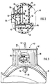
- FIG. 1 shows a Lighting device in the form of a headlight in one vertical longitudinal section according to a first Embodiment
- Figure 2 a in Figure 1 with II designated section of a recording for a light source the headlight in an enlarged view
- Figure 3 den Headlights according to the first embodiment partially in a section along line III-III in Figure 1
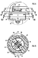
- Figure 4 one designated in Figure 3 with IV Section in an enlarged view
- Figure 5 den Headlights according to the first embodiment in one Cross section along line V-V in Figure 4 with the inclusion in an assembly position
- Figure 6 the same section with the Recording in a locking position
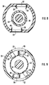
- Figure 7 den Headlights according to the first embodiment in one Cross section along line VII-VII in Figure 4
- Figure 8 den Headlights according to the first embodiment in one Cross section along line VIII-VIII in Figure 4
- Figure 9 den Headlights according to the first embodiment in one Cross section along lines IX-IX in Figure 4
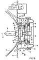
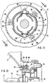
- Figure 10 den Headlights according to a second embodiment in a vertical longitudinal
- the headlight preferably has one Plastic existing housing 10 in which at least one Reflector 12 is arranged and its light exit opening is covered with a translucent pane 14. Of the Reflector 12 is concavely curved and points in its Vertex area an opening 16 through which one Light source 18 is insertable. The opening 16 at least on surrounding part of its circumference stands from the back of the reflector 12 in one piece with this a neck 20 after back off. The neck 20 runs at least approximately coaxially to the optical axis 13 of the reflector 12.
- the reflector 12 is preferably made of plastic, so that the neck 20 at the manufacture of the reflector 12 by injection molding can easily be molded onto this.
- the neck 20 of the reflector 12 has two cutouts on its circumference 22 on, for example, at least approximately each other are arranged diametrically opposite.
- the cutouts 22 are delimited on all sides by the neck 20.
- the connection elements 24 have how 4 and 7 each show a spring bar 26 on which in the recesses 22 in the circumferential direction of the Neck 20 are arranged under resilient compression and thus the connecting elements 24 non-positively in the Fix recesses 22.
- connection elements 24 as shown in Figure 4 and Figure 8 in a position closer to the reflector 12 compared to the spring bars 26 arranged area each issued from these Biting edges 28 on the edges of the recesses 22 claw and thus the connecting elements 24 fix it in the recesses 22.
- the Connection elements 24 are preferably made of bent Sheet.
- the connecting elements 24 is in each case an electrical within the housing 10 Line 32 connected in the form of a cable leading to an am Guide housing 10 arranged connector part 34.
- the Plug part 34 protrudes outwards from the housing 10 Contact pins 35, which are surrounded by a flange 36, which is preferably integrally formed on the housing 10 and with which a plug part, not shown, can be joined is the leading to the vehicle electrical system electrical lines is connected.
- the housing 10 has an opening 38 on its rear side through which the neck 20 of the reflector 12 with its Protrudes through the end area.
- the opening 38 is at least arranged approximately coaxially to the reflector neck 20 and from a neck 39 protruding outward from the housing 10.
- On the reflector neck 20 is a receptacle 40 for the light source 18 attachable, in which the light source 18 is pre-assembled.
- the light source 18 can be a gas discharge lamp or as in the illustrated embodiment, an incandescent lamp, which has a base from which a plate 41 radially towards protrudes outside and one or two as shown protrude electrical contact pins 42 axially.
- the receptacle 40 has a plastic, in particular existing base body on the front, to Reflector 12 facing end Centering section 43 in which the light source 18th is centered over its base plate 41.
- a fastening section 44 with, for example, two radially outwardly projecting ribs 45, each over extend less than half the circumference of the receptacle 40 and run at least approximately in the shape of a circular arc.
- Ribs 45 are two circumferential areas 46 with a smaller one radial extension than the ribs 45 arranged likewise at least approximately in the form of a circular arc are and over the remaining scope of the recording 40th run.
- the fastening section 44 in turn closes from Reflector 12 off a central section 48 in which two in cross-section formed approximately rectangular depressions 49 are.
- the central section 48 connects a radially projecting collar away from the reflector 12 50 on, in which a circumferential annular groove 51 is formed and at the end region pointing away from the reflector 12 flange 52 projecting radially outward again is trained.
- annular groove 51 is an elastic Sealing ring 53 inserted, for example in the form of an O-ring.
- Two contact elements 54 are held on the receptacle 40, each one arranged in a recess 49
- the contact elements 54 also have their Flat receptacles 55 radially outside of the depressions 49 outwardly projecting connecting portions 58, the in particular as shown in Figures 1 and 2 V-shaped are curved and at the radially outward end portions facing each have a tab pin 59 is trained. Radially inside the flat pins 59 stands from the connecting sections 58 of each Reflector 12 away in the axial direction, a flat pin 60th from the through a slot 61 or a groove of the Fastening section 44 radially inside the ribs 45 passes through and through one issued from this Locking hook 62 is secured.
- the flat pins 59 are arranged such that this at most in the radial direction protrude as far or less as the ribs 45 and are covered by the ribs 45 in the circumferential direction.
- the two contact elements 54 are preferably identical formed and arranged symmetrically on the receptacle 40. Furthermore, the contact elements 54 preferably consist of punched and bent sheet.
- each a resilient element 64 arranged, for example as in Figure 2 and Figure 5 represented as a leaf spring made of sheet metal or plastic can be trained.
- the contact elements 54 are in Direction of the optical axis 13 into the receptacle 40 slidable, with the flat receptacles 55 the Leaf springs 64 are tensioned and a preload in Obtained direction of the optical axis 13.
- the reflector neck 20 has at least approximately circular cross-section, with this on the from Reflector 12 pioneering edges of the recesses two protruding radially inwards, each less than the half-circumferential ribs 66 are formed, between which two peripheral areas 67 with a larger one Internal cross section are formed. Each rib 66 instructs an end region pointing in the circumferential direction is radial protrusion 68 projecting still further inwards. Of the between the reflector neck 20 and the opening 38 of the Housing 10 remaining area is by means of a Closure element 70 closed, the flexible Material such as rubber.
- the Closure element 70 has an inner flange 71, with which it on the outer circumference of the reflector neck 20th is pushed, and an outer flange 72, with which it is pushed onto the neck 39 on the housing 10. By doing Area between its flanges 71.72 can do that Closure element 70, for example, as in FIG. 1 shown have a U-shaped bead 73.
- the flexible closure element 70 is a movement of the Reflector 12 relative to the housing 10 allows as to an adjustment of the reflector 12 in the housing 10 for Alignment of the light beam reflected by this is required.
- the receptacle 40 has one on its collar 50 and flange 52 formed, away from the reflector 12 externally projecting web 74, which is approximately perpendicular to the collar 50 and runs radially.
- the assembly of the light source 18 in the Recording 40 and its assembly on the reflector neck 20 explained.
- the base of the light source 18 is in the receptacle 40 introduced, the tabs 42 in the Flat receptacles 55 enter and their base plate 41 in Centering section 43 is recorded and centered.
- the Light source 18 is thus held in the receptacle 40 and electrically connected to the contact elements 54.
- the receptacle 40 with the light source 18 arranged therein is from the back of the headlight with the Glass bulb of the light source 18 ahead in the direction of optical axis 13 inserted into the reflector neck 20.
- the receptacle 40 must first be in a figure 5 shown rotational position are in the ribs 45 to the ribs 66 of the reflector neck 20 in The circumferential direction are offset, so that the ribs 45 of the receptacle 40 through the peripheral regions 67 of the Reflector neck 20 can pass through and accordingly the ribs 66 of the reflector neck 20 through the Circumferential areas 46 of the receptacle 40 can pass through.
- the receptacle 40 is so in the direction of the optical axis 13 inserted far until the light source 18 with her Base plate 41 on one inside the reflector neck 20 arranged bearing surface 76 on the reflector 12 for contact comes and thus with respect to the reflector 12 in the direction of optical axis 13 assumes the intended position.
- the Light source 18 occurs with its base in the opening 16 in Apex of the reflector 12 and becomes radial Direction aligned with respect to the optical axis 13. over this position, the receptacle 40 must still in Direction of the optical axis 13 are inserted, wherein the contact elements 54 are moved in the receptacle 40 and the leaf springs 64 are biased as indicated above become.
- the ribs 45 are closer to the receptacle 40 arranged on the reflector 12 as the ribs 66 of the Reflector neck 20 so that the receptacle 40 clockwise starting from its position shown in FIG rotated their locking position shown in Figure 6 can be.
- the ribs 45 of the receptacle 40 thereby reach over the ribs 66 of the reflector neck 20 so that the Recording 40 no longer in the direction of the optical axis 13 can be deducted from the reflector neck 20.
- the recording 40 is turned in the locking direction until the in Locking-facing edges of the ribs 45 on the Protrusions 68 of the reflector neck 20 abut and Recording 40 can no longer be rotated.
- the ribs 45 and peripheral areas 46 of the receptacle 40 as well the ribs 66 and peripheral regions 67 of the reflector neck 20 together form a bayonet catch for fastening the Recording 40 on the reflector neck 20.
- the arrangement of the U-shaped sections 30 as flat receptacles and the Flat pins 59 can also be reversed, in which case the U-shaped sections 30 as flat receptacles instead of Flat pins 59 arranged on the contact elements 54 are and accordingly the tabs 59 instead of U-shaped sections 30 on the connection elements 24 are arranged.
- the inner flange 71 of the closure element 70 is through one or more of the reflector neck 20 to the outside protruding lugs 78 and the flange 52 of the receptacle 40 the reflector neck 20 secured so that it is not from this can slide down.
- the receptacle 40 dips with its collar 50 in the end region of the reflector neck 20 and seals the reflector neck 20 and the opening 16 of the reflector 12 through the sealing ring 53.
- For assembly and disassembly of the Recording 40 does not need to remove the closure element 70 to be, since this is not arranged on the receptacle 40 but on the reflector neck 20.
- To remove the holder 40 it is twisted counterclockwise into its in Figure 5 shown rotational position and can then in the direction the optical axis 13 from the reflector neck 20 be pulled out.
- the lighting device is shown in FIGS. 10 to 12 again in the form of a headlight according to a second Embodiment shown.
- the basic structure the headlight is the same as the first Embodiment and below are essentially only the different training of the headlamp according to described the second embodiment.
- the reflector As shown in FIG Vertex area, the opening 16 for the light source 18.
- the opening 16 at least over part of its circumference is surrounding from the back of the reflector 12 Approach 80 from, the end face of the bearing surface 76 for the Base plate 41 of the light source 18 forms.
- With radial Distance to the opening 16 and the approach 80 is from the Rear of the reflector 12 also an opening 16 Collar 81 surrounding at least part of its circumference from.
- the collar 81 faces as in FIGS.
- domes 82 represented several domes 82 distributed over its circumference, for example three domes 82 evenly distributed are arranged. However, less or more than three domes 82 are provided.
- the domes 82 have in their end faces pointing away from reflector 12 each Hole 83 on.
- a neck part 84 is connected, the Neck 20 of the reflector 12 according to the first Embodiment replaced and preferably as the Reflector 12 is made of plastic and by injection molding is made.
- the neck 84 has on its front, the End region facing reflector 12 in its inner circumference a cross-sectional expansion through which in the neck 84 a annular shoulder 85 is formed at the front of the Collar 81 of the reflector 12 comes to rest, the End region of the neck 84 engages over the collar 81. From End region of the neck 84 are in accordance with the number and Arrangement of the domes 82 of the reflector 12 three lugs 86 radially to the outside.
- the lugs 86 each have an opening 87 on the circumferential direction of the neck 84 on one side can be open.
- the neck 84 is by means of the Openings 87 of its tabs 86 and inserted into the holes 83 of the dome 82 screws 88 on the reflector 12 attached.
- the screws 88 can already be installed of the neck 84 is screwed into the bores 83 of the domes 82 followed by the neck 84 with its noses 86 to the domes 82 offset in the circumferential direction on the Collar 81 of the reflector 12 is pushed on and then, by turning the neck 84, the screws 88 into the openings 87 of the lugs 86 through their open Peripheral sides and finally the screws 88 can be tightened.
- the neck 84 has a central portion in its Includes two recesses 90, for example at least approximately diametrically opposite each other are arranged and, for example, approximately rectangular are trained. There is one in each of the recesses 90 arranged electrical connector 91, which is a U-shaped Has basic shape, this over which the Recess 90 to the reflector 12 bounding edge 92 of the Neck 84 is inserted so that its leg 93.94 the Reach over edge 92 and with its free ends to the reflector 12 point out.
- the edge 92 can protrude outwards
- leg 93 of the connecting element 91 can resilient latching hook 96 projecting inwards be, which engages behind the projection 95, whereby the Connection element 91 is held positively on the neck 84.
- the connecting elements 91 On the legs 93 arranged on the outer circumference of the neck 84 the connecting elements 91, the lines 32 are connected.
- the recesses 90 from the reflector 12 edge of the neck 84 delimiting are like the neck 20 according to the first embodiment, which are each about extending less than half the circumference of the neck 84 Ribs 66 formed between which two peripheral regions 67 without the ribs 66 and with a larger inner cross section are trained.
- the housing 10 has on its back the opening 38 through which the neck 84 with its from The reflector 12 protrudes through the end region.
- the receptacle 40 for the light source 18 is on the neck 84 Can be attached like a bayonet, which is the same as for the first embodiment is formed.
- the two on the receptacle 40 arranged contact elements 54 are in essentially as in the first embodiment and how this is held on the receptacle 40. Deviating from first exemplary embodiment are the flat pins 97 of the Contact elements 54 according to the second embodiment not arranged radially to the optical axis 13 but approximately parallel to this and proceed from the Connecting sections 58 to the reflector 12 with radial Distance outside the centering portion 43 of the receptacle 40. Both contact elements 54 are preferably also here identically designed and symmetrical on the receptacle 40 arranged.
- the closure element 70 is made of flexible Material arranged the same as the first Embodiment is formed.
- the closure element 70 is with its outer flange 72 on the neck 39 of Housing 10 and with its inner flange 71 on the neck 84 postponed.
- the main difference of the Headlamp according to the second embodiment to the according to the first embodiment is that Connection elements 91 are not formed on the reflector 12 Neck 20 but on the trained as a separate part and neck 84 connected to the reflector 12 are arranged.
- the connection elements 91 are in the headlight according to the second exemplary embodiment via the reflector 12 attached neck 84 arranged indirectly on the reflector 12.
- the closure element 70 is between the housing 10 and over the neck 84 connected to the reflector 12 indirectly the Reflector 12 arranged.
- connection elements 91 with the parallel to arranged optical axis 13 and in the circumferential direction open tab receptacles from their legs 94 and the arrangement parallel to the optical axis 13
- Flat pins 97 of the contact elements 54 of the receptacle 40 can also with the headlight according to the first Embodiment with directly molded on the reflector 12 Neck 20 are provided.
- Training the Headlamp according to the second embodiment with the Neck 84 formed as a separate part offers the advantage a simple manufacture of the reflector 12.
Landscapes
- Engineering & Computer Science (AREA)
- General Engineering & Computer Science (AREA)
- Mechanical Engineering (AREA)
- Non-Portable Lighting Devices Or Systems Thereof (AREA)
Applications Claiming Priority (4)
| Application Number | Priority Date | Filing Date | Title |
|---|---|---|---|
| DE19736518 | 1997-08-22 | ||
| DE19736518 | 1997-08-22 | ||
| DE19822895 | 1998-05-22 | ||
| DE19822895A DE19822895A1 (de) | 1997-08-22 | 1998-05-22 | Beleuchtungseinrichtung für Fahrzeuge |
Publications (3)
| Publication Number | Publication Date |
|---|---|
| EP0898114A2 true EP0898114A2 (fr) | 1999-02-24 |
| EP0898114A3 EP0898114A3 (fr) | 2001-01-31 |
| EP0898114B1 EP0898114B1 (fr) | 2007-10-31 |
Family
ID=26039373
Family Applications (1)
| Application Number | Title | Priority Date | Filing Date |
|---|---|---|---|
| EP98113770A Expired - Lifetime EP0898114B1 (fr) | 1997-08-22 | 1998-07-23 | Dispositif d'éclairage pour véhicules |
Country Status (2)
| Country | Link |
|---|---|
| EP (1) | EP0898114B1 (fr) |
| DE (1) | DE59814113D1 (fr) |
Cited By (3)
| Publication number | Priority date | Publication date | Assignee | Title |
|---|---|---|---|---|
| EP1243845A1 (fr) * | 2001-03-21 | 2002-09-25 | Valeo Vision | Projecteur lumineux pour véhicule automobile, et dispositif de fixation d'une lampe pour un tel projecteur |
| EP1288566A2 (fr) | 2001-08-31 | 2003-03-05 | Valeo Vision | Agencement pour la connexion électrique d'une lampe |
| ES2318977A1 (es) * | 2005-07-20 | 2009-05-01 | Automotive Lighting Reutilingen Gmbh | Instalacion de iluminacion para automoviles. |
Citations (1)
| Publication number | Priority date | Publication date | Assignee | Title |
|---|---|---|---|---|
| DE4418399A1 (de) | 1994-05-26 | 1995-11-30 | Bosch Gmbh Robert | Beleuchtungseinrichtung für Fahrzeuge |
Family Cites Families (3)
| Publication number | Priority date | Publication date | Assignee | Title |
|---|---|---|---|---|
| FR2704938B1 (fr) * | 1993-05-03 | 1995-08-04 | Valeo Vision | Dispositif d'eclairage ou de signalisation pour vehicule automobile, comportant une lampe a haute tension et un boitier perfectionne de circuit d'alimentation. |
| JP2965849B2 (ja) * | 1994-03-09 | 1999-10-18 | 株式会社小糸製作所 | 車両用灯具 |
| US5664870A (en) * | 1995-06-28 | 1997-09-09 | Koito Manufacturing Co., Ltd. | Vehicular lamps |
-
1998
- 1998-07-23 EP EP98113770A patent/EP0898114B1/fr not_active Expired - Lifetime
- 1998-07-23 DE DE59814113T patent/DE59814113D1/de not_active Expired - Lifetime
Patent Citations (1)
| Publication number | Priority date | Publication date | Assignee | Title |
|---|---|---|---|---|
| DE4418399A1 (de) | 1994-05-26 | 1995-11-30 | Bosch Gmbh Robert | Beleuchtungseinrichtung für Fahrzeuge |
Cited By (5)
| Publication number | Priority date | Publication date | Assignee | Title |
|---|---|---|---|---|
| EP1243845A1 (fr) * | 2001-03-21 | 2002-09-25 | Valeo Vision | Projecteur lumineux pour véhicule automobile, et dispositif de fixation d'une lampe pour un tel projecteur |
| FR2822526A1 (fr) * | 2001-03-21 | 2002-09-27 | Valeo Vision | Projecteur lumineux pour vehicule, et dispositif de fixation d'une lampe pour un tel projecteur |
| EP1288566A2 (fr) | 2001-08-31 | 2003-03-05 | Valeo Vision | Agencement pour la connexion électrique d'une lampe |
| ES2318977A1 (es) * | 2005-07-20 | 2009-05-01 | Automotive Lighting Reutilingen Gmbh | Instalacion de iluminacion para automoviles. |
| ES2318977B2 (es) * | 2005-07-20 | 2010-02-08 | Automotive Lighting Reutlingen Gmbh | Instalacion de iluminacion para automoviles. |
Also Published As
| Publication number | Publication date |
|---|---|
| EP0898114A3 (fr) | 2001-01-31 |
| EP0898114B1 (fr) | 2007-10-31 |
| DE59814113D1 (de) | 2007-12-13 |
Similar Documents
| Publication | Publication Date | Title |
|---|---|---|
| DE69420243T2 (de) | Fahrzeugleuchte | |
| DE3030427A1 (de) | Beleuchtungseinrichtung fuer kraftfahrzeuge | |
| DE2124930B2 (de) | Glühlfunpenfassung, insbesondere für Kraftfahrzeug-Leuchten | |
| DE10004700A1 (de) | Scheinwerfer für Kraftfahrzeuge | |
| DE19546271B4 (de) | Scheinwerfer für Fahrzeuge mit einem verschwenkbaren Reflektor | |
| EP0766036B1 (fr) | Douille pour projecteur de véhicule automobile et projecteur de véhicule automobile muni d'une telle douille | |
| EP1646116B1 (fr) | Unité d'éclairage pour le domaine automobile | |
| EP0898114B1 (fr) | Dispositif d'éclairage pour véhicules | |
| DE19547718A1 (de) | Scheinwerfer für Fahrzeuge | |
| DE19822895A1 (de) | Beleuchtungseinrichtung für Fahrzeuge | |
| DE10009589B4 (de) | Befestigungssystem für eine Lichtquelle an einem Reflektor eines Scheinwerfers | |
| DE4445223A1 (de) | Scheinwerfer für Fahrzeuge | |
| DE19861321B4 (de) | Beleuchtungseinrichtung für Fahrzeuge | |
| EP0306687B1 (fr) | Projecteur pour véhicule automobile | |
| DE4418399A1 (de) | Beleuchtungseinrichtung für Fahrzeuge | |
| DE10303329A1 (de) | Lampenfassung für einen Kraftfahrzeugscheinwerfer und zur Aufnahme einer solchen Lampenfassung vorgesehener Scheinwerferreflektor | |
| DE29502977U1 (de) | Stecker zur Kontaktierung einer Gasentladungslampe | |
| EP1559951B1 (fr) | Feu de véhicule et procédé de montage pour feu de véhicule | |
| EP1043546A2 (fr) | Dispositif formant douille de lampe dans un projecteur de véhicule | |
| DE19645647C2 (de) | Lampenhalterung als Bestandteil eines Kraftfahrzeugscheinwerfers | |
| DE19537815A1 (de) | Scheinwerfer für Fahrzeuge | |
| DE19922298B4 (de) | Befestigungssystem für eine Gasentladungslampe an einem Reflektor eines Scheinwerfers | |
| EP0673487B1 (fr) | Connexion electrique d'une source de lumiere | |
| DE7433223U (de) | Fahrzeugscheinwerfer | |
| DE20301294U1 (de) | Beleuchtungseinrichtung für Fahrzeuge |
Legal Events
| Date | Code | Title | Description |
|---|---|---|---|
| PUAI | Public reference made under article 153(3) epc to a published international application that has entered the european phase |
Free format text: ORIGINAL CODE: 0009012 |
|
| AK | Designated contracting states |
Kind code of ref document: A2 Designated state(s): DE ES FR IT |
|
| AX | Request for extension of the european patent |
Free format text: AL;LT;LV;MK;RO;SI |
|
| PUAL | Search report despatched |
Free format text: ORIGINAL CODE: 0009013 |
|
| AK | Designated contracting states |
Kind code of ref document: A3 Designated state(s): AT BE CH CY DE DK ES FI FR GB GR IE IT LI LU MC NL PT SE |
|
| AX | Request for extension of the european patent |
Free format text: AL;LT;LV;MK;RO;SI |
|
| RIC1 | Information provided on ipc code assigned before grant |
Free format text: 7F 21S 8/10 A, 7F 21V 17/02 B, 7F 21V 23/00 B |
|
| 17P | Request for examination filed |
Effective date: 20010731 |
|
| AKX | Designation fees paid |
Free format text: DE ES FR IT |
|
| RAP1 | Party data changed (applicant data changed or rights of an application transferred) |
Owner name: AUTOMOTIVE LIGHTING REUTLINGEN GMBH |
|
| GRAP | Despatch of communication of intention to grant a patent |
Free format text: ORIGINAL CODE: EPIDOSNIGR1 |
|
| GRAS | Grant fee paid |
Free format text: ORIGINAL CODE: EPIDOSNIGR3 |
|
| GRAA | (expected) grant |
Free format text: ORIGINAL CODE: 0009210 |
|
| AK | Designated contracting states |
Kind code of ref document: B1 Designated state(s): DE ES FR IT |
|
| REF | Corresponds to: |
Ref document number: 59814113 Country of ref document: DE Date of ref document: 20071213 Kind code of ref document: P |
|
| PG25 | Lapsed in a contracting state [announced via postgrant information from national office to epo] |
Ref country code: ES Free format text: LAPSE BECAUSE OF FAILURE TO SUBMIT A TRANSLATION OF THE DESCRIPTION OR TO PAY THE FEE WITHIN THE PRESCRIBED TIME-LIMIT Effective date: 20080211 |
|
| EN | Fr: translation not filed | ||
| PLBE | No opposition filed within time limit |
Free format text: ORIGINAL CODE: 0009261 |
|
| STAA | Information on the status of an ep patent application or granted ep patent |
Free format text: STATUS: NO OPPOSITION FILED WITHIN TIME LIMIT |
|
| 26N | No opposition filed |
Effective date: 20080801 |
|
| PG25 | Lapsed in a contracting state [announced via postgrant information from national office to epo] |
Ref country code: FR Free format text: LAPSE BECAUSE OF FAILURE TO SUBMIT A TRANSLATION OF THE DESCRIPTION OR TO PAY THE FEE WITHIN THE PRESCRIBED TIME-LIMIT Effective date: 20080704 |
|
| PG25 | Lapsed in a contracting state [announced via postgrant information from national office to epo] |
Ref country code: IT Free format text: LAPSE BECAUSE OF NON-PAYMENT OF DUE FEES Effective date: 20080731 |
|
| PGFP | Annual fee paid to national office [announced via postgrant information from national office to epo] |
Ref country code: DE Payment date: 20110923 Year of fee payment: 14 |
|
| PG25 | Lapsed in a contracting state [announced via postgrant information from national office to epo] |
Ref country code: DE Free format text: LAPSE BECAUSE OF NON-PAYMENT OF DUE FEES Effective date: 20130201 |
|
| REG | Reference to a national code |
Ref country code: DE Ref legal event code: R119 Ref document number: 59814113 Country of ref document: DE Effective date: 20130201 |