EP0898146B1 - Connexion de deux pièces de coque d'un missile - Google Patents
Connexion de deux pièces de coque d'un missile Download PDFInfo
- Publication number
- EP0898146B1 EP0898146B1 EP98114354A EP98114354A EP0898146B1 EP 0898146 B1 EP0898146 B1 EP 0898146B1 EP 98114354 A EP98114354 A EP 98114354A EP 98114354 A EP98114354 A EP 98114354A EP 0898146 B1 EP0898146 B1 EP 0898146B1
- Authority
- EP
- European Patent Office
- Prior art keywords
- fuselage
- connection
- edge
- fuselage portion
- set forth
- Prior art date
- Legal status (The legal status is an assumption and is not a legal conclusion. Google has not performed a legal analysis and makes no representation as to the accuracy of the status listed.)
- Expired - Lifetime
Links
- 230000002093 peripheral effect Effects 0.000 description 2
- 238000010276 construction Methods 0.000 description 1
- 230000001419 dependent effect Effects 0.000 description 1
- 238000004519 manufacturing process Methods 0.000 description 1
- 230000036316 preload Effects 0.000 description 1
Images
Classifications
-
- F—MECHANICAL ENGINEERING; LIGHTING; HEATING; WEAPONS; BLASTING
- F42—AMMUNITION; BLASTING
- F42B—EXPLOSIVE CHARGES, e.g. FOR BLASTING, FIREWORKS, AMMUNITION
- F42B15/00—Self-propelled projectiles or missiles, e.g. rockets; Guided missiles
- F42B15/36—Means for interconnecting rocket-motor and body section; Multi-stage connectors; Disconnecting means
Definitions
- the invention relates to a connection for connecting two tubular body parts of a missile according to the preamble of claim 1.
- the known type of pipe connection is particularly unsatisfactory Connecting tubular fuselage parts of highly agile missiles. Kick at these extreme stresses on the pipe connections.
- Pipe connection is known in which the edge regions to be connected each consist of two Circumferential sections with different diameters exist. The The inner diameter of one circumferential section corresponds to an assembly tolerance the outer diameter of the other peripheral portion. They have Pipe parts the same design of the edge area, but by 180 ° around Connection axis rotated. The pipe connection is made by the pipe parts are pushed into each other and screwed with radial connecting screws become.
- the pipe connection has an asymmetrical radial screw connection and has the The advantage that it brings about a good form fit.
- US-A-3 781 042 discloses a connection for connecting two tubular ones Fuselage parts of a missile according to the preamble of claim 1.
- this Connection are clamping elements along the inner circumference of the second fuselage part intended.
- Each clamping element is provided with a threaded hole in which one connecting screw each can be screwed in.
- the clamping elements cooperate Inclined surface so that the two fuselage parts when tightening the screws move axially against each other and are thus tightened together.
- the invention has for its object a high-strength and highly rigid connection to create two tubular fuselage parts of a missile.
- connection should be detachable.
- the connection should enable easy assembly. Costs and manufacturing effort should be low.
- the construction volume should be small.
- the connection should leave a large free cross section. Increases in the outside diameter due to the pipe connection should be avoided.
- the connection should continue to be free of play.
- the clamping segments are separate peripheral sections of a ring, the outer diameter of which is the inner diameter of the second body part corresponds, the threads are not in the inner part of the fuselage, but in the Clamping segments.
- connection has a high pressure due to the high load-bearing components Rigidity and strength.
- the wall thickness of the Connecting edge of the second part of the fuselage is slight. Through this and through the division into several clamping segments can achieve higher preloads. This leads to higher ones sustainable operational forces before the connection takes off.
- Embodiments of the invention are the subject of the dependent claims.
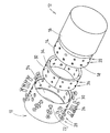
- the figure shows a perspective view of the connection.
- a first fuselage part of a missile is designated by 10 in FIG.
- the first part of the fuselage 10 is to be connected to a second fuselage part 12 of a missile.
- the Fuselage parts 10 and 12 are tubular parts of the fuselage of a missile.
- the fuselage part 12 has an edge 14.
- the edge 14 has a smaller one Diameter than the remaining part 16 of the fuselage part 12.
- In the edge 14 are Bores 18 in two rows 20 along the circumference of the edge 14.
- the fuselage part 10 has an edge 22.
- the edge 22 has an inner diameter that except for a small assembly tolerance the outer diameter of the edge 14 of the corresponds to other fuselage part 12. This inner diameter can be smaller than that Inner diameter of the remaining part 24 of the fuselage part 10.
- In the edge 22 there are Bores 26 in two rows 28 along the circumference of the edge 22. The bores 26 are designed so that the heads of screws 30 which are inserted into the holes 26 are retractable.
- clamping segments 32 For the connection of the two fuselage parts 10 and 12 there are clamping segments 32 intended.
- the assembled Clamping segments 32 a ring.
- This ring has an outer diameter that corresponds to the Corresponds to the inner diameter of the edge 14 of the fuselage part 12.
- the clamping segments 32 there are bores 34 which run along two rows 36 the circumference are arranged.
- the holes 34 are provided with internal threads that correspond to the thread of the connecting screws 30.
- the holes 18 in the Edge 14, the holes 26 in the edge 22 and the holes 34 in the Clamping segments 32 are arranged with respect to one another such that they lie one above the other when the fuselage parts 10 and 12 are pushed together and the clamping segments lie within the edge 14.
- the connecting screws 30 are then through the Bores 26 and 18 in the thread of the bore 34 in the clamping segment screwed.
Landscapes
- Engineering & Computer Science (AREA)
- Chemical & Material Sciences (AREA)
- Aviation & Aerospace Engineering (AREA)
- Combustion & Propulsion (AREA)
- General Engineering & Computer Science (AREA)
- Mutual Connection Of Rods And Tubes (AREA)
- Clamps And Clips (AREA)
Claims (6)
- Assemblage destiné à assembler deux éléments de fuselage (10,12) en forme de tuyau d'un missile, les diamètres extérieurs des éléments de fuselage (10,12) concordant sensiblement l'un avec l'autre et pour lequel les éléments de fuselage (10,12) sont susceptibles d'être emmanchés l'un dans l'autre,caractérisé par le fait que(a) le diamètre intérieur du bord (22) du premier élément de fuselage (10) devant être assemblé avec le second élément de fuselage (12) correspondant, déduction faite d'une tolérance d'accouplement, au diamètre extérieur du bord (14) du second élément de fuselage (12) devant être assemblé avec le premier élément de fuselage (10),(b) les bords (22,14) des éléments de fuselage (10,12) devant être assemblés étant pourvus de perçages radiaux (26,20) destinés aux vis d'assemblage (30),(c) des segments de serrage (32) étant pourvus de perçages filetés (34) le long de la circonférence intérieure du second élément de fuselage (12) dans lesquels les vis d'assemblage (30) sont susceptibles d'être vissées, et(d) le diamètre extérieur de l'assemblage de tuyaux correspondant sensiblement aux diamètres extérieurs des éléments de fuselage (10,12) devant être assemblés,(e) plusieurs vis d'assemblage (30) sont susceptibles d'être vissées dans chaque segment de serrage (32), et(f) les segments de serrage (32) forment des segments circonférentiels d'une bague séparés les uns des autres dont le diamètre extérieur correspond au diamètre intérieur du second élément de fuselage (12).
- Assemblage selon la revendication 1, caractérisé par le fait que les vis d'assemblage (30) sont disposées sur deux rangées (28) le long dé la circonférence du bord (22) du premier élément de fuselage (10).
- Assemblage selon la revendication 1 ou 2, caractérisé par le fait que l'épaisseur de paroi du bord (14) du second élément de fuselage (12) est inférieure à l'épaisseur de paroi restante du second élément de fuselage (12).
- Assemblage selon l'une des revendications 1 à 3, caractérisé par le fait que l'épaisseur de paroi du bord (14) du second élément de fuselage (12) est inférieure à l'épaisseur de paroi du bord (22) du premier élément de fuselage (10).
- Assemblage selon l'une des revendications 1 à 4, caractérisé par le fait que les têtes des vis d'assemblage (30) sont renfoncées dans le bord (22) du premier élément de fuselage (10).
- Assemblage selon l'une des revendications 1 à 5, caractérisé par le fait que les segments de serrage (32) se composent d'un matériau hautement résistant.
Applications Claiming Priority (2)
| Application Number | Priority Date | Filing Date | Title |
|---|---|---|---|
| DE19735452A DE19735452C2 (de) | 1997-08-16 | 1997-08-16 | Rohrverbindung, insbesondere zum Verbinden zweier rohrförmiger Rumpfteile eines Flugkörpers |
| DE19735452 | 1997-08-16 |
Publications (3)
| Publication Number | Publication Date |
|---|---|
| EP0898146A2 EP0898146A2 (fr) | 1999-02-24 |
| EP0898146A3 EP0898146A3 (fr) | 1999-05-26 |
| EP0898146B1 true EP0898146B1 (fr) | 2001-10-10 |
Family
ID=7839101
Family Applications (1)
| Application Number | Title | Priority Date | Filing Date |
|---|---|---|---|
| EP98114354A Expired - Lifetime EP0898146B1 (fr) | 1997-08-16 | 1998-07-30 | Connexion de deux pièces de coque d'un missile |
Country Status (3)
| Country | Link |
|---|---|
| US (1) | US6098928A (fr) |
| EP (1) | EP0898146B1 (fr) |
| DE (2) | DE19735452C2 (fr) |
Families Citing this family (17)
| Publication number | Priority date | Publication date | Assignee | Title |
|---|---|---|---|---|
| DE10141169A1 (de) † | 2001-08-22 | 2003-03-13 | Diehl Munitionssysteme Gmbh | Artillerierakete |
| RU2249131C1 (ru) * | 2003-10-17 | 2005-03-27 | Общество с ограниченной ответственностью "АВВИ" | Способ соединения деталей |
| US7325771B2 (en) * | 2004-09-23 | 2008-02-05 | The Boeing Company | Splice joints for composite aircraft fuselages and other structures |
| US7681834B2 (en) * | 2006-03-31 | 2010-03-23 | Raytheon Company | Composite missile nose cone |
| FR2915458B1 (fr) * | 2007-04-25 | 2010-01-01 | Airbus France | Assemblage de panneaux de fuselage d'un avion |
| US20080296432A1 (en) * | 2007-06-04 | 2008-12-04 | Kernkamp Industries Corporation | Method of extending length of aircraft to increase interior space |
| DE102009021369A1 (de) * | 2009-05-12 | 2010-11-18 | Airbus Operations Gmbh | Verfahren zur Herstellung eines Flugzeugrumpfes und Flugzeugrumpf |
| DE102013102812B4 (de) * | 2013-03-19 | 2017-01-26 | Airbus Operations Gmbh | Rumpfstruktur für ein Verkehrsmittel, Verkehrsmittel und Verfahren zum Herstellen einer Rumpfstruktur für ein Verkehrsmittel |
| CN103759597B (zh) * | 2014-01-14 | 2015-06-17 | 北京航空航天大学 | 一种导弹舱段径向单斜衬套螺栓连接结构 |
| US10634473B2 (en) * | 2014-01-29 | 2020-04-28 | Raytheon Company | Internally coupleable joint |
| US8894011B1 (en) * | 2014-02-14 | 2014-11-25 | The Boeing Company | Aircraft fuselage constructed of aircraft fuselage sections screwed together |
| US20170241460A1 (en) * | 2014-09-10 | 2017-08-24 | Gripple Limited | Stiffening assembly |
| DE102015106761A1 (de) * | 2015-04-30 | 2016-11-03 | Airbus Operations Gmbh | Montage von Strukturelementen in der Luftfahrt |
| US10920811B2 (en) | 2018-02-15 | 2021-02-16 | Raytheon Company | Component assembly for high-precision joining of components |
| CN111332492B (zh) * | 2020-03-06 | 2021-06-01 | 北京机电工程研究所 | 一种飞行器舱段无缆对接装置及其对接方法 |
| RU2738623C1 (ru) * | 2020-06-16 | 2020-12-15 | Акционерное Общество "Государственное Машиностроительное Конструкторское Бюро "Радуга" Имени А.Я. Березняка" | Узел стыковки отсеков |
| CN112344808A (zh) * | 2020-10-11 | 2021-02-09 | 中国运载火箭技术研究院 | 插接结构及舱段组件 |
Family Cites Families (12)
| Publication number | Priority date | Publication date | Assignee | Title |
|---|---|---|---|---|
| US759834A (en) * | 1902-12-03 | 1904-05-10 | Benjamin M Steele | Means for uniting sheet-metal parts. |
| GB106153A (en) * | 1916-05-22 | 1917-05-17 | Accles & Pollock Ltd | A New or Improved Joint or Coupling for Connecting Tubes, Tubing, and the like. |
| DE692866C (de) * | 1937-04-23 | 1940-06-27 | Benno Schilde | Blechstossverbindung |
| US2945704A (en) * | 1957-07-23 | 1960-07-19 | Hughes Aircraft Co | Nose section-quick disconnect |
| DE1173736B (de) * | 1960-05-20 | 1964-07-09 | Inst Stahlbau | Stossverbindung fuer Geruestrohre od. dgl. |
| US3345946A (en) * | 1960-11-02 | 1967-10-10 | Gen Motors Corp | Rocket stage separator |
| DE1500729A1 (de) * | 1966-11-26 | 1969-06-04 | Freytag Franz Juergen | UEberlappverbindung fuer Formteile aus Kunststoff |
| US3572778A (en) * | 1969-05-26 | 1971-03-30 | Cassel Thomas Richard | Pipe coupling |
| US3781042A (en) * | 1970-09-30 | 1973-12-25 | Raytheon Co | Joint having force converting means |
| US4556591A (en) * | 1981-09-25 | 1985-12-03 | The Boeing Company | Conductive bonded/bolted joint seals for composite aircraft |
| DE19615716A1 (de) * | 1996-04-22 | 1997-10-23 | Bodenseewerk Geraetetech | Rohrverbindung, insbesondere zum Verbinden zweier rohrförmiger Rumpfteile eines Flugkörpers |
| US5884864A (en) * | 1996-09-10 | 1999-03-23 | Raytheon Company | Vehicle having a ceramic radome affixed thereto by a compliant metallic transition element |
-
1997
- 1997-08-16 DE DE19735452A patent/DE19735452C2/de not_active Expired - Fee Related
-
1998
- 1998-07-30 EP EP98114354A patent/EP0898146B1/fr not_active Expired - Lifetime
- 1998-07-30 DE DE59801680T patent/DE59801680D1/de not_active Expired - Lifetime
- 1998-08-11 US US09/132,263 patent/US6098928A/en not_active Expired - Lifetime
Also Published As
| Publication number | Publication date |
|---|---|
| DE19735452C2 (de) | 1999-07-22 |
| EP0898146A3 (fr) | 1999-05-26 |
| EP0898146A2 (fr) | 1999-02-24 |
| US6098928A (en) | 2000-08-08 |
| DE59801680D1 (de) | 2001-11-15 |
| DE19735452A1 (de) | 1999-03-04 |
Similar Documents
| Publication | Publication Date | Title |
|---|---|---|
| DE19735452C2 (de) | Rohrverbindung, insbesondere zum Verbinden zweier rohrförmiger Rumpfteile eines Flugkörpers | |
| DE4205063C2 (de) | Rohrflansch für ein Kühlmittelrohr | |
| DE102010040419A1 (de) | Schellenloser Klemmverband | |
| DE3116289A1 (de) | Spanndorn mit einer hydraulisch dehnbaren spannhuelse | |
| EP2478234B1 (fr) | Articulation à rotule et feuille lisse pour la rotule | |
| DE102017218016A1 (de) | Bolzenanordnung, Verbindungsanordnung und Verfahren zum Demontieren einer Verbindungsanordnung | |
| DE3838935A1 (de) | Kupplungsstueck | |
| DE1500942B1 (de) | Anwendung einer schnellkupplung bei einer schraubverbindung | |
| EP2882600A1 (fr) | Structure de roue d'une automobile | |
| CH663832A5 (de) | Rohrschelle zum verbinden zweier rohrenden. | |
| EP0803675B1 (fr) | Raccord pour tubes en particulier pour connecter des éléments tubulaires du fuselage d'un corps volant | |
| EP1776539A1 (fr) | Bague coupante metallique | |
| DE1231979B (de) | Arbeitszylinder fuer Druckmittelanlagen | |
| EP0078048B1 (fr) | Elément d'assemblage à jonction détachable pour barres, tuyaux de gauche ou parallèles ou pour éléments analogues | |
| DE3882467T2 (de) | Dichtung mit variablen Durchmessern für die Abdichtung zwischen einem äusseren Rohr und inneren Rohren oder Stangen. | |
| DE4206781A1 (de) | Nach dem stuelpprinzip arbeitendes deformationselement | |
| WO1982003440A1 (fr) | Raccordement etanche de tubes en matiere plastique resistant aux forces de poussee | |
| DE102018127682B4 (de) | Anordnung mit einer Justagevorrichtung zur Lageeinstellung zweier miteinander verbundener Bauteile | |
| DE60101708T2 (de) | Montagesystem für Komponenten | |
| WO2010124815A1 (fr) | Corps cylindrique à base d'une matière synthétique renforcée de fibre | |
| DE2529138A1 (de) | Flansch-platten-anordnung, sowie verfahren zu deren herstellung | |
| DE2839761C2 (de) | Knoten zur Verbindung mehrerer stabförmiger Elemente | |
| EP0108722A1 (fr) | Manchon pour tuyaux | |
| DE102024133180B3 (de) | Vorrichtung zur Trennung zweier Raketenstufen | |
| DE19526085A1 (de) | Gelenkige Verbindung zweier Rohre einer Abgasanlage |
Legal Events
| Date | Code | Title | Description |
|---|---|---|---|
| PUAI | Public reference made under article 153(3) epc to a published international application that has entered the european phase |
Free format text: ORIGINAL CODE: 0009012 |
|
| AK | Designated contracting states |
Kind code of ref document: A2 Designated state(s): DE FR GB IT SE |
|
| AX | Request for extension of the european patent |
Free format text: AL;LT;LV;MK;RO;SI |
|
| PUAL | Search report despatched |
Free format text: ORIGINAL CODE: 0009013 |
|
| AK | Designated contracting states |
Kind code of ref document: A3 Designated state(s): AT BE CH CY DE DK ES FI FR GB GR IE IT LI LU MC NL PT SE |
|
| AX | Request for extension of the european patent |
Free format text: AL;LT;LV;MK;RO;SI |
|
| 17P | Request for examination filed |
Effective date: 19990422 |
|
| AKX | Designation fees paid |
Free format text: DE FR GB IT SE |
|
| 17Q | First examination report despatched |
Effective date: 20000823 |
|
| GRAG | Despatch of communication of intention to grant |
Free format text: ORIGINAL CODE: EPIDOS AGRA |
|
| GRAG | Despatch of communication of intention to grant |
Free format text: ORIGINAL CODE: EPIDOS AGRA |
|
| GRAH | Despatch of communication of intention to grant a patent |
Free format text: ORIGINAL CODE: EPIDOS IGRA |
|
| GRAH | Despatch of communication of intention to grant a patent |
Free format text: ORIGINAL CODE: EPIDOS IGRA |
|
| GRAA | (expected) grant |
Free format text: ORIGINAL CODE: 0009210 |
|
| AK | Designated contracting states |
Kind code of ref document: B1 Designated state(s): DE FR GB IT SE |
|
| REF | Corresponds to: |
Ref document number: 59801680 Country of ref document: DE Date of ref document: 20011115 |
|
| REG | Reference to a national code |
Ref country code: GB Ref legal event code: IF02 |
|
| GBT | Gb: translation of ep patent filed (gb section 77(6)(a)/1977) |
Effective date: 20011220 |
|
| ET | Fr: translation filed | ||
| PLBE | No opposition filed within time limit |
Free format text: ORIGINAL CODE: 0009261 |
|
| STAA | Information on the status of an ep patent application or granted ep patent |
Free format text: STATUS: NO OPPOSITION FILED WITHIN TIME LIMIT |
|
| 26N | No opposition filed | ||
| REG | Reference to a national code |
Ref country code: FR Ref legal event code: PLFP Year of fee payment: 18 |
|
| PGFP | Annual fee paid to national office [announced via postgrant information from national office to epo] |
Ref country code: FR Payment date: 20150626 Year of fee payment: 18 |
|
| PGFP | Annual fee paid to national office [announced via postgrant information from national office to epo] |
Ref country code: DE Payment date: 20150923 Year of fee payment: 18 Ref country code: GB Payment date: 20150721 Year of fee payment: 18 |
|
| PGFP | Annual fee paid to national office [announced via postgrant information from national office to epo] |
Ref country code: SE Payment date: 20150721 Year of fee payment: 18 |
|
| PGFP | Annual fee paid to national office [announced via postgrant information from national office to epo] |
Ref country code: IT Payment date: 20150727 Year of fee payment: 18 |
|
| REG | Reference to a national code |
Ref country code: DE Ref legal event code: R119 Ref document number: 59801680 Country of ref document: DE |
|
| REG | Reference to a national code |
Ref country code: SE Ref legal event code: EUG |
|
| GBPC | Gb: european patent ceased through non-payment of renewal fee |
Effective date: 20160730 |
|
| PG25 | Lapsed in a contracting state [announced via postgrant information from national office to epo] |
Ref country code: FR Free format text: LAPSE BECAUSE OF NON-PAYMENT OF DUE FEES Effective date: 20160801 Ref country code: DE Free format text: LAPSE BECAUSE OF NON-PAYMENT OF DUE FEES Effective date: 20170201 Ref country code: SE Free format text: LAPSE BECAUSE OF NON-PAYMENT OF DUE FEES Effective date: 20160731 |
|
| REG | Reference to a national code |
Ref country code: FR Ref legal event code: ST Effective date: 20170331 |
|
| PG25 | Lapsed in a contracting state [announced via postgrant information from national office to epo] |
Ref country code: GB Free format text: LAPSE BECAUSE OF NON-PAYMENT OF DUE FEES Effective date: 20160730 |
|
| PG25 | Lapsed in a contracting state [announced via postgrant information from national office to epo] |
Ref country code: IT Free format text: LAPSE BECAUSE OF NON-PAYMENT OF DUE FEES Effective date: 20160730 |