EP0898313A1 - Piezoelektrischer Transformator - Google Patents
Piezoelektrischer Transformator Download PDFInfo
- Publication number
- EP0898313A1 EP0898313A1 EP97114229A EP97114229A EP0898313A1 EP 0898313 A1 EP0898313 A1 EP 0898313A1 EP 97114229 A EP97114229 A EP 97114229A EP 97114229 A EP97114229 A EP 97114229A EP 0898313 A1 EP0898313 A1 EP 0898313A1
- Authority
- EP
- European Patent Office
- Prior art keywords
- symmetry
- primary
- electrode
- plane
- electrodes
- Prior art date
- Legal status (The legal status is an assumption and is not a legal conclusion. Google has not performed a legal analysis and makes no representation as to the accuracy of the status listed.)
- Granted
Links
- 239000000463 material Substances 0.000 claims description 33
- 230000004044 response Effects 0.000 claims description 11
- 230000003247 decreasing effect Effects 0.000 claims description 3
- 239000007787 solid Substances 0.000 claims 1
- 230000010287 polarization Effects 0.000 description 17
- 208000031968 Cadaver Diseases 0.000 description 15
- 230000008602 contraction Effects 0.000 description 8
- 230000005684 electric field Effects 0.000 description 7
- 230000008878 coupling Effects 0.000 description 6
- 238000010168 coupling process Methods 0.000 description 6
- 238000005859 coupling reaction Methods 0.000 description 6
- 230000009466 transformation Effects 0.000 description 6
- 229920000297 Rayon Polymers 0.000 description 3
- 239000004020 conductor Substances 0.000 description 3
- 238000004519 manufacturing process Methods 0.000 description 3
- 239000002964 rayon Substances 0.000 description 3
- 239000003990 capacitor Substances 0.000 description 2
- 230000000694 effects Effects 0.000 description 2
- 208000031872 Body Remains Diseases 0.000 description 1
- 230000015572 biosynthetic process Effects 0.000 description 1
- 239000000919 ceramic Substances 0.000 description 1
- 230000007423 decrease Effects 0.000 description 1
- 230000008021 deposition Effects 0.000 description 1
- 230000005284 excitation Effects 0.000 description 1
- 238000009413 insulation Methods 0.000 description 1
- 239000002184 metal Substances 0.000 description 1
- 230000004048 modification Effects 0.000 description 1
- 238000012986 modification Methods 0.000 description 1
- 244000045947 parasite Species 0.000 description 1
- 229910000679 solder Inorganic materials 0.000 description 1
Images


Classifications
-
- H—ELECTRICITY
- H10—SEMICONDUCTOR DEVICES; ELECTRIC SOLID-STATE DEVICES NOT OTHERWISE PROVIDED FOR
- H10N—ELECTRIC SOLID-STATE DEVICES NOT OTHERWISE PROVIDED FOR
- H10N30/00—Piezoelectric or electrostrictive devices
- H10N30/40—Piezoelectric or electrostrictive devices with electrical input and electrical output, e.g. functioning as transformers
Definitions
- a piezoelectric transformer with these characteristics is described in US Patent 2,974,296 where it is represented by figure 1.
- the body of this transformer in the form of an elongated hollow cylinder axially polarized.
- Primary voltage is applied between two electrodes surrounding the body on the one hand and else in the middle of its length, so that this body vibrates in a longitudinal mode.
- Secondary voltage is collected between two electrodes surrounding the body, each at one end of the latter.
- this transformer has the disadvantage of being relatively difficult to manufacture in large series of made of its shape of hollow and elongated circular cylinder. Its cost price is therefore relatively high.
- the body of this transformer has the shape of a disc circular whose central part is polarized axially and the outer annular part is polarized radially.
- Primary voltage is applied between two electrodes arranged on either side of the part central body, so that it vibrates in a radial mode.
- Secondary voltage is collected between one of these latter electrodes and a third electrode arranged on the lateral surface of the body.
- the body of this transformer has the shape of a ring circular, the first half of which, in a plan view, is axially polarized.
- the second half of this ring is made up of two tangentially polarized parts, the polarization directions of these two parts being opposite to one another.
- Primary voltage is applied between two electrodes arranged on either side of the first half of the ring, so that the body vibrates in what is called a tangential mode.
- Voltage secondary is collected between one of these two electrodes and a third electrode surrounding the second half of the ring where the two parts polarized in opposite directions meet.
- the two transformers which have just been described also have, among other things, the disadvantage of being relatively difficult to manufacture, because their body has several parts which must be differently polarized. Their cost price is therefore also relatively high.
- the fundamental resonant frequency of any object vibrating in one of its modes of vibration depends among other things on the dimensions of this object and that, all other things being equal, this frequency of fundamental resonance is all the higher as these dimensions are small.
- An example of such a device where the available part is very limited consists of a wristwatch including the housing, which is usually no more than three or four centimeters inside diameter, must contain many components.
- a device lighting or electroluminescent display that it is often advantageous to use in a watch, should be powered by an AC voltage having an amplitude of a few tens of volts.
- a watch is usually powered by a battery or accumulator providing a DC voltage of the order of 1.5 to 3 volts.
- Such DC voltage can be easily converted to alternating voltage using a circuit simple electronics but the magnitude of this voltage alternative is obviously also around 1.5 to 3 volts.
- transformers piezoelectric are also described in the patent US 2,974,296 already mentioned as well as in the patents US 5,241,236, US 5,365,141, US 5,371,430 and US 5,440,195. But these transformers cannot be used for solve the problem mentioned above because when their footprint is small, the resonant frequency fundamental to their body's mode of vibration is also very high. It should also be noted that the body of all these transformers has the shape of a rectangular parallelepiped, and that these transformers do not therefore do not meet the general definition given above.
- An object of the present invention is therefore to propose a piezoelectric transformer that meets this general definition but which has sufficient dimensions weak so that it can be easily used in a device where space is limited while being arranged so that his body vibrates in a fashion having a fundamental frequency low enough to that the secondary voltage it produces is usable in all cases where the frequency of the secondary voltage produced by a known transformer having the same space requirement is too high.
- FIGS 1 to 3 schematically represent a embodiment of the transformer according to this invention, designated by the general reference 1.
- the transformer 1 comprises a body 2 formed of a single piece of piezoelectric material whose nature will not be specified as it can be any of the various piezoelectric materials well known to specialists.
- the body 2 has the shape of a cylindrical ring having two plane faces 3 and 4 parallel to each other and shown in Figures 1 and 3 respectively.
- the outer and inner side surfaces of the body 2 each have the shape of a circular cylinder right having a circular axis of symmetry designated by the reference A.
- These exterior side surfaces and interior as well as the cylinders which constitute them will be respectively designated by the references E and I.
- the intersections of these lateral surfaces E and I with the planes of faces 3 and 4, which constitute the exterior and interior contours of these faces 3 and 4 and which are obviously circles centered on the axis A, will respectively designated by the references E1, E2, I1 and I2.
- the piezoelectric material of the body 2 is polarized uniformly in a direction parallel to the A axis and in a direction from side 3 to side 4. This polarization is symbolized by the arrows P represented in Figure 2.
- the transformer 2 still has eight electrodes arranged on the face 3 of the body 2 and designated by the references 5 to 12.
- electrodes 5 to 8 are arranged on the periphery of face 3, outside of circle C1. These electrodes 5 to 8 therefore occupy slightly less of the half the width of this face 3 and fit each in a center angle slightly less than 90 °. In addition, these electrodes 5 to 8 are isolated electrically from each other.
- the electrodes 9 to 12 are arranged on the part internal of face 3 of body 2, inside the circle C1, and also occupy slightly less than half of the width of this face 3 while leaving a space of insulation between them and the electrodes 5 to 8. These electrodes 9 to 12 are also each part of a angle at the center slightly less than 90 °, and are respectively located in zones Z1 to Z4 defined above.
- the electrodes 9 to 12 are also isolated electrically from each other but each of they are connected to one, and only one, of electrodes 5 to 8 by conductive tracks designated by the references 13 to 16.
- tracks 13 to 16 connect electrodes 5 and 10, 6 and 11, 7 and 12 respectively, and 8 and 9.
- tracks 13 to 16 are arranged with so that each of them includes one of the points where the traces of planes N1 and N2 intersect the mean circle C1.
- the transformer 1 also comprises eight other electrodes arranged on the face 4 of the body 2 and designated by the references 17 to 24. These electrodes 17 to 24 are respectively located opposite electrodes 5 to 12 and are similar to these. These electrodes 17 to 24 do not will therefore not be described in more detail.
- conductive tracks 25 to 28 connect electrodes 17 and 22, 18 and 23, 19 and 24, and 20 and 21.
- these tracks 25 to 28 are arranged so that each of them includes a points where the traces of the N1 and N2 planes intersect the circle C2.
- the thickness of the electrodes 6, 8, 10, 12, 18, 20, 22 and 24 visible in section in the figure 2 has been greatly exaggerated to improve the clarity of this figure 2.
- these electrodes, as well as all those that are not visible and that the conductive tracks 13 to 16 and 25 to 28, are produced conventionally by simple deposition on the faces 3 and 4 of the body 2 of a metal layer extremely thin.
- the transformer 1 also includes means for connection of its electrodes 5 to 12 and 17 to 24 with the circuits which provide it with the excitation voltage of the vibration of his body 2 and that use tension resulting from this vibration. This vibration and the way it produces this last tension will described later.
- connection means are constituted by rods 29 to 36 of conductive material each having one end fixed, for example by solder, to one of the conductive tracks 13 to 16 and 25 to 28.
- these rods 29 to 36 are preferably fixed to these tracks 13 to 16 and 25 to 28 at the points where the traces of planes N1 and N2 intersect the circles C1 and respectively C2, as shown in Figures 1 and 3.
- transformer 1 comprises two planes of symmetry S1 and S2 perpendicular one to the other, which are at the same time the bisector planes of the angles formed by the planes N1 and N2 mentioned above.
- the traces of these planes S1 and S2 are indicated in the Figures 1 and 3 by dashed lines bearing the same references.
- each of the electrodes 5, 7, 9, 11, 17, 19, 21 and 23 is symmetrical with respect to the plane S1
- each of the electrodes 6, 8, 10, 12, 18, 20, 22 and 24 is symmetrical about the S2 plane.
- electrodes 5, 9, 17 and 21 are respectively symmetrical electrodes 7, 11, 19 and 23 relative to the plane S2, while the electrodes 6, 10, 18 and 22 are symmetrical of electrodes 8, 12, 20 and 24 respectively with respect to the plan S1.
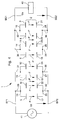
- transformer 1 The operation of transformer 1 described above will be explained in a particular case, taken at by way of nonlimiting example, illustrated by FIG. 4.
- the connecting rods 29 and 31 are electrically connected to each other, as well as to a BP1 terminal.
- the connecting rods 33 and 35 are electrically connected to each other, as well as to a BP2 terminal.
- the connecting rods 30 and 32 are electrically connected to each other and to a terminal BS1, and connecting rods 34 and 36 are also electrically connected to each other and to a BS2 terminal.
- the terminals BP1 and BP2 are intended to receive the voltage alternative applied to transformer 1, or voltage primary.
- the terminals BS1 and BS2 are those between which the voltage produced by this transformer 1, or secondary voltage, can be collected. These tensions primary and secondary will be called respectively Up voltage and Us voltage.
- BP1 and BP2 terminals may very well not exist in practical, the voltage Up then being applied directly between the connecting rods 29 and 33, for example.
- the terminals BS1 and BS2 may very well not exist, the voltage Us then being collected directly between the connecting rods 30 and 34, for example.
- the electrodes 5 to 12 and 17 to 24 of the transformer 1 also have and shown in Figure 4, so very schematic, as well as the conductive tracks 13 to 16 and 25 to 28.
- the electrodes 5, 7, 10 and 12 are connected to each other and to terminal BP1, likewise than electrodes 17, 19, 22 and 24 with terminal BP2.
- the electrodes 6, 8, 9 and 11 are connected between them and with the terminal BS1, as well as the electrodes 18, 20, 21 and 23 with terminal BS2.
- the outer electrodes located in two diametrically opposite areas are connected together and to the interior electrodes located in the other two zones.
- the external electrodes 5 and 7 located on face 3 in zones Z1 and, respectively, Z3 are connected to the electrodes interior 10 and 12 located on the same face 3 but in zones Z2 and, respectively, Z4.
- the source supplying transformer 1 the voltage primary alternative Up and the device powered by the secondary alternating voltage Us supplied by the transformer 1 have also been shown in Figure 4 with the references 41 and, respectively, 42.
- tension Primary Up can be any.
- this tension Up can be sinusoidal, or have the shape generally qualified as square in which it alternately a first constant value and a second value constant equal in absolute value to the first but of sign opposite to this.
- device 42 will not be specified here because it can be any of the various devices that need to be powered by a alternating voltage such as Us voltage.
- the AC voltage Up causes the application of an electric field F, also alternative, to the four body parts 2 which are respectively located between the pairs of electrodes 5 and 17, 7 and 19, 10 and 22, and 12 and 24.
- these electrodes 5, 7, 10, 12, 17, 19, 22 and 24 will be called primary electrodes, and the parts of the body 2 which they delimit will be called parts primaries of this body 2.
- the electric field F has a direction parallel to that of axis A, and therefore to the direction of polarization P of the material of the body 2, and a direction which is alternately the same as that of this polarization P and the opposite direction.
- electromechanical coupling transverse of the field F with the material of the body 2, called commonly electromechanical coupling 31, causes the application of mechanical stresses to the four parts body primaries 2 defined above.
- Field F having alternatively the two directions mentioned above, these mechanical stresses cause alternately, always in a well-known way, a contraction and a expansion of these four primary parts in all directions perpendicular to axis A.
- a first and a second of the four primary parts defined above i.e. those which are located between electrodes 5 and 17 and, respectively 7 and 19 are external parts of the body 2 respectively located in a first and a second of the four areas also defined above, that is to say zones Z1 and Z3.
- This first and this second primary part are symmetrical to each other relative to the plane S2 and each of them is symmetrical with respect to the plan S1.
- the third and the fourth primary part i.e. those located between electrodes 10 and 22, and, respectively, 12 and 24, are internal parts of the body 2 respectively located in the third and fourth areas of body 2, that is to say zones Z2 and Z4.
- This third and this fourth primary part are symmetrical one of the other with respect to the plane S1, and each of them is symmetrical about the S2 plane.
- the particular mode of vibration of the body 2 mentioned above is called bi-elliptical because, when this body 2 vibrates in this mode, it alternately takes the shape of a first and a second elliptical ring. These elliptical rings are further variable like this will be shown later.
- the main axes of the first and second outer elliptical cylinder are respectively located in planes S1 and S2, as well as the large axes of the first and second elliptical cylinder interior.
- the minor axes of the first and second outer elliptical cylinder are respectively located in the S2 and S1 planes, as well as the minor axes of the first and second inner elliptical cylinder. All these major axes and all these minor axes are obviously perpendicular to the axis A.
- outer wall E and the wall inner I of body 2 have the shape of one of the cylinders elliptical outdoor and, respectively, indoor mentioned above, the length of the major axis of each of these elliptical cylinders varies regularly in increasing from a minimum value to a value maximum then decreasing to its minimum value.
- the outer E and inner I walls then take the shape of the other outer elliptical cylinder and, respectively, interior after going through the form circular cylinder that they have in the absence of body vibration 2.
- the length of the minor axis of each of these elliptical cylinders also varies regularly but in the opposite direction, this length decreasing from a maximum value up to a minimum value then increasing to its maximum value, so that the body volume 2 remains constant.
- the average cylinder C also alternately takes the form of a prime and of a second elliptical cylinder, which will be called means, whose main axes are also respectively located in planes S1 and S2, and whose minor axes are also located respectively in the S2 and S1 planes.
- the length of the major axes and minor axes of these average elliptical cylinders varies so analogous to that which has been described above.
- the minimum length of the major axis of each of the outer elliptical cylinders, interiors and means mentioned above, and the length maximum of their minor axis is obviously respectively equal to the diameter of the outer wall E, of the wall interior I and the middle cylinder C in the absence of vibration.
- the maximum length of these major axes and the minimum length of these small axes depends on various factors such as, for example, characteristics mechanical and electromechanical of the material of the body 2, and the frequency and amplitude of the primary voltage Up.
- this maximum length of these large axes and this minimum length of these small axes have respectively their largest and their smallest value when the frequency of the voltage Up is equal to the fundamental resonant frequency fr of the mode of bi-elliptical resonance of the body 2.
- Figure 5 shows examples of the various ellipses formed by the intersection of the elliptical cylinders described above with the plane of the face 3 of the body 2. These ellipses will be qualified in the same way as the elliptical cylinders which form them.
- first inner ellipse and second inner ellipse have been shown, also in dashed lines, and respectively designated by the references I11 and I12.
- first middle ellipse and second middle ellipse were shown in phantom and respectively designated by the references C11 and C12.
- electromechanical coupling 31 As is well known, electromechanical coupling 31, already mentioned, between these alternative constraints and the polarization P of the material of the body 2 causes the formation of an electric field F 'in these parts secondary.
- This field F ′ is also alternative, and it has a direction parallel to that of this polarization P and a meaning which is alternately the same as that of this polarization P and the opposite direction of the latter.
- this field F ' causes the appearance of the secondary AC voltage Us between the pairs electrodes, listed above, which delimit the secondary parts of the body 2, and therefore between the terminals BS1 and BS2 of transformer 1.
- a first and a second of the four secondary parts that is to say those located between the electrodes 9 and 21 and, 11 and 23 respectively are internal parts of the body 2 and are respectively located in the first and in the second of the zones defined above, that is to say zones Z1 and Z3, where the first is also located and, respectively, the second primary part also defined above.
- This first and this second secondary part are also symmetrical to each other with respect to the plane S2, and each of them is symmetrical with respect to the plan S1.
- the third and fourth part secondary i.e. those located between the electrodes 6 and 18 and, respectively, 8 and 20 are external parts of the body 2 and are respectively located in the third and in the fourth of the defined zones above, i.e. zones Z2 and Z4, where are also the third and, respectively, the fourth part primary also defined above.
- This third and this fourth secondary part are also symmetrical from each other with respect to the plane S1, and each of them is symmetrical with respect to the plane S2.
- body 2 is isotropic in all directions perpendicular to the A axis. follows that the parts of the body 2 which have been chosen, in this example, to be primary parts could just as easily have been chosen to be secondary parts, and vice versa.
- the electrodes that have been chosen for to be primary electrodes could obviously have been chosen to be secondary electrodes, and vice versa.
- each faces 3 and 4 of the body 2 of the transformer 1 comprises first and second primary electrodes which are external electrodes symmetrical to each other by relation to a first of the planes S1 and S2 and symmetrical, each, compared to the second of these S2 and S2 planes.
- Each of these faces 3 and 4 also has a third and fourth primary electrode which are internal electrodes symmetrical to each other by compared to the second of the plans defined above and symmetrical, each, with respect to the first of these planes.
- each of the faces 3 and 4 has a first and second secondary electrode which are internal electrodes symmetrical to each other by compared to the first of the plans defined above and symmetrical, each with respect to the second of these plans.
- each of the faces 3 and 4 has a third and fourth secondary electrode which are external electrodes symmetrical to each other by compared to the second of the plans defined above and symmetrical, each, with respect to the first of these planes.
- the first cylinder medium elliptical defined also above cuts the planes N1 and N2 along four lines parallel to the axis A whose position is fixed regardless of the amplitude of the vibration of the body 2 and which are also those according to which the average circular cylinder intersects the planes N1 and N2.
- the second medium elliptical cylinder intersects these planes N1 and N2 along the same four lines.
- Figure 6 illustrates the variation of the coefficient ⁇ mentioned above depending on the Ri / Re ratio between the inner radius Ri and the outer radius Re of the body 2.
- this coefficient ⁇ varies, in this case, from 1.37 approximately for a Ri / Re ratio equal to zero, i.e. for a full disc, about 0.17 for a ratio Ri / Re equal to 0.9.
- Equation (1) above shows that for the same material that in the previous example, the coefficient ⁇ must be equal to 0.30.
- the Ri / Re ratio must therefore be equal to 0.7 according to Figure 6, which gives, for the inner radius Ri of this body 2, a value of 4.2 mm.
- the thickness of the body 2 that is to say its dimension in the direction parallel to the axis A, does not intervene in equations (1) and (2) above, so the resonant frequency fr and the ratio of transformation T are independent of this thickness.
- mechanical strength body 2 which obviously depends on its thickness, must however be sufficient for it to withstand without damage the mechanical stresses to which it is subjected during its vibration.
- the thickness of the body 2 influences the value of the impedances primary and secondary transformer 1.
- this body 2 can generally have a thickness of the order of 1 mm, or even less than 1 mm, depending on the material of which it is made, without its mechanical strength does not become insufficient.
- the value exact of this thickness is obviously determined from so that the primary and secondary impedances have the desired values.
- FIG. 7 illustrates another embodiment of the transformer according to the present invention which is designated in this case by the general reference 51.
- the transformer 51 includes a body 52 comprising two pieces in the form of circular rings 53 and 54 identical to each other and having an axis of symmetry circular also designated by the reference A.
- the rings 53 and 54 are made of a piezoelectric material which can also be any of the piezoelectric materials well known to specialists, and they are fixed to each other through a thin metallic layer of an electrically material conductor which covers the entire surface of the rings 53 and 54 facing each other. We will see more far that this metallic layer constitutes an electrode municipality which will be designated by the reference 55.
- the piezoelectric material of the rings 53 and 54 is uniformly polarized in a direction parallel to the axis A, but the direction of polarization of the material of the ring 53 is opposite to the direction of polarization of the material of the ring 54.
- these polarizations which are symbolized by the arrows designated respectively by the references P1 and P2, are directed from the outer faces 56 and 57 of the rings 53 and 54 towards electrode 55.
- P1 and P2 can all as well be directed in opposite directions.
- the transformer 51 also includes electrodes arranged on the external faces 56 and 57 rings 53 and 54, conductive tracks connecting these electrodes two by two, and connecting rods intended to allow these electrodes to be connected to a primary and source AC voltage source that the secondary AC voltage is intended for feed.
- These components of transformer 51 will not not described again here as they are identical to corresponding components of transformer 1 shown in Figures 1 and 3 and will be designated by the same references as these.
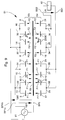
- FIG 8 illustrates one way to operate the transformer 51 which has just been described.
- the connecting rods 29 and 31 are connected to each other and to the first primary terminal BP1, as in the case of transformer 1 illustrated by the Figure 4.
- the connecting rods 33 and 35 are also interconnected, as in the case of Figure 4, but they are also linked to the first primary terminal BP1.
- the connecting rods 30 and 32 are connected between them and at the first secondary terminal BS1, as in the case of Figure 4.
- the rods of connection 34 and 36 are interconnected as in this same case of figure 4, but they are on the other hand also connected to the first secondary terminal BS1.
- the common electrode 55 is connected to the second primary terminal BP2 and at the second terminal secondary BS2.
- the primary parts and the parts side of the body 52 are arranged one by compared to others exactly like those of body 2 of transformer 1. Similarly, on each of the faces 56 and 57 of body 52, the primary electrodes and the electrodes are arranged in relation to each other exactly like the ones on sides 3 and 4 of the body 2 of the transformer 1.
- transverse electromechanical coupling of the field F1 with the material of the ring 53 and of the field F2 with the material of the ring 54 therefore causes the application of mechanical stresses identical to all parts primary of these rings 53 and 54, and these constraints alternately cause a contraction and a expansion of these primary parts in all directions perpendicular to axis A.
- Figure 9 illustrates another way of doing things. operate the transformer 51 described using the figure 7.
- the connecting rods 29 and 31 are connected to each other and to a first primary terminal BP1a, while the connecting rods 30 and 32 are connected to each other and to a second primary terminal BP1b.
- the common electrode 55 is connected to a third BP2 primary terminal.
- the connecting rods 33 and 35 are connected to each other and to a first terminal secondary BS1, while the connecting rods 34 and 36 are connected to each other and to a second terminal secondary BS2.
- the transformer 51 is supplied by a source, designated by 61, which provides two voltages alternatives Up1 and Up2 together constituting the voltage Primary Up, which have the same frequency and the same amplitude, but which are 180 ° out of phase one by compared to each other.
- these tensions Up1 and Up2 have polarities which are always inverse one of the other.
- This source 61 will not be described further in detail, because its realization is within the reach of a specialist in the subject.
- Source 61 is connected to terminals BP1a, BP1b and BP2 so that the voltage Up1 is applied between the terminal BP1a and terminal BP2, and that the voltage Up2 is applied between terminal BP1b and the same terminal BP2.
- the primary parts of the body 52 form two groups, the first of these groups being constituted by the primary parts located between the common electrode 55 and the electrodes 5, 7, 10 and 12, and the second of these groups being made up of primary parts located between this common electrode 55 and electrodes 6, 8, 9 and 11.
- the secondary parts of the body 52 form also two groups, the first of which is made up of secondary parts located between the common electrode 55 and electrodes 17, 19, 22 and 24, and the second of which consists of the abutments located between this common electrode 55 and the electrodes 18, 20, 21 and 23.
- all the primary parts and all the secondary parts therefore belong respectively ring 53 and ring 54.
- the external parts i.e. those which are respectively located opposite electrodes 6 and 8
- the internal parts i.e. those which are respectively located opposite the electrodes 10 and 12
- the fundamental resonant frequency of the vibration mode bi-elliptical of the body of a transformer according to the present invention is very much lower than that body vibration modes of known transformers described above.
- a transformer according to the present invention can therefore provide a secondary voltage having a frequency also significantly lower than the one provided by a known transformer.
- the transformation ratio of a transformer according to the present invention is the same order than that of a known transformer or even higher than the latter.
- a transformer according to the present invention is therefore particularly well suited to be used in a device such as a wristwatch where the place available is limited, in all cases where it is necessary to obtain a relatively alternating voltage high with a relatively low frequency.
- the piezoelectric material which is made of the transformer body according to this invention, or each of the parts forming this body, is uniformly polarized in the direction perpendicular to its faces simplifies the manufacture of this body and reduces the cost price of this transformer.
- the body of a transformer according to the present invention the form of a full disc, without central opening, this disc can be made in one piece, like the body 2 of transformer 1 of figures 1 to 3, or be formed of two identical parts like the body 52 of the transformer 51 of figure 7.
- the various electrodes arranged on the transformer body according to the present invention can have different forms from the one they have in the examples described, and their links can be performed differently.
Landscapes
- Engineering & Computer Science (AREA)
- Power Engineering (AREA)
- Dc-Dc Converters (AREA)
Priority Applications (2)
| Application Number | Priority Date | Filing Date | Title |
|---|---|---|---|
| EP97114229A EP0898313B1 (de) | 1997-08-18 | 1997-08-18 | Piezoelektrischer Transformator |
| DE69726134T DE69726134T8 (de) | 1997-08-18 | 1997-08-18 | Piezoelektrischer Transformator |
Applications Claiming Priority (1)
| Application Number | Priority Date | Filing Date | Title |
|---|---|---|---|
| EP97114229A EP0898313B1 (de) | 1997-08-18 | 1997-08-18 | Piezoelektrischer Transformator |
Publications (2)
| Publication Number | Publication Date |
|---|---|
| EP0898313A1 true EP0898313A1 (de) | 1999-02-24 |
| EP0898313B1 EP0898313B1 (de) | 2003-11-12 |
Family
ID=8227233
Family Applications (1)
| Application Number | Title | Priority Date | Filing Date |
|---|---|---|---|
| EP97114229A Expired - Lifetime EP0898313B1 (de) | 1997-08-18 | 1997-08-18 | Piezoelektrischer Transformator |
Country Status (2)
| Country | Link |
|---|---|
| EP (1) | EP0898313B1 (de) |
| DE (1) | DE69726134T8 (de) |
Cited By (3)
| Publication number | Priority date | Publication date | Assignee | Title |
|---|---|---|---|---|
| EP1206709B1 (de) * | 1999-07-29 | 2006-06-07 | Mineral Lassen LLC | Piezo-elektrisches etikett |
| WO2008104489A1 (de) * | 2007-02-26 | 2008-09-04 | Epcos Ag | Transformatoranordnung mit einem piezoelektrischen transformator |
| WO2014104378A1 (en) * | 2012-12-26 | 2014-07-03 | Canon Kabushiki Kaisha | Piezoelectric element, stator for oscillatory wave motor, oscillatory wave motor, driving control system, optical apparatus, and method for making stator for oscillatory wave motor |
Citations (1)
| Publication number | Priority date | Publication date | Assignee | Title |
|---|---|---|---|---|
| JPS61125179A (ja) * | 1984-11-22 | 1986-06-12 | Rion Co Ltd | 円環状圧電トランス |
-
1997
- 1997-08-18 EP EP97114229A patent/EP0898313B1/de not_active Expired - Lifetime
- 1997-08-18 DE DE69726134T patent/DE69726134T8/de active Active
Patent Citations (1)
| Publication number | Priority date | Publication date | Assignee | Title |
|---|---|---|---|---|
| JPS61125179A (ja) * | 1984-11-22 | 1986-06-12 | Rion Co Ltd | 円環状圧電トランス |
Non-Patent Citations (1)
| Title |
|---|
| PATENT ABSTRACTS OF JAPAN vol. 010, no. 313 (E - 448) 24 October 1986 (1986-10-24) * |
Cited By (8)
| Publication number | Priority date | Publication date | Assignee | Title |
|---|---|---|---|---|
| EP1206709B1 (de) * | 1999-07-29 | 2006-06-07 | Mineral Lassen LLC | Piezo-elektrisches etikett |
| USRE42449E1 (en) | 1999-07-29 | 2011-06-14 | Mineral Lassen Llc | Piezo-electric tag |
| CN101086768B (zh) * | 1999-07-29 | 2012-10-24 | 拉森矿物有限责任公司 | 无线通信设备 |
| EP1691426B1 (de) * | 1999-07-29 | 2014-04-30 | Mineral Lassen LLC | Piezoelektrische Wandler |
| WO2008104489A1 (de) * | 2007-02-26 | 2008-09-04 | Epcos Ag | Transformatoranordnung mit einem piezoelektrischen transformator |
| US7990028B2 (en) | 2007-02-26 | 2011-08-02 | Epcos Ag | Transformer arrangement with a piezoelectric transformer |
| WO2014104378A1 (en) * | 2012-12-26 | 2014-07-03 | Canon Kabushiki Kaisha | Piezoelectric element, stator for oscillatory wave motor, oscillatory wave motor, driving control system, optical apparatus, and method for making stator for oscillatory wave motor |
| US9893269B2 (en) | 2012-12-26 | 2018-02-13 | Canon Kabushiki Kaisha | Piezoelectric element, stator for oscillatory wave motor, oscillatory wave motor, driving control system, optical apparatus, and method for making stator for oscillatory wave motor |
Also Published As
| Publication number | Publication date |
|---|---|
| DE69726134T2 (de) | 2004-07-22 |
| EP0898313B1 (de) | 2003-11-12 |
| DE69726134T8 (de) | 2004-12-30 |
| DE69726134D1 (de) | 2003-12-18 |
Similar Documents
| Publication | Publication Date | Title |
|---|---|---|
| CH691519A5 (fr) | Transformateur piézo-électrique. | |
| EP2862210A1 (de) | Aktuator für einen ultraschallmotor und ultraschallmotor mit mindestens einem solchen aktuator | |
| FR2872501A1 (fr) | Microresonateur composite a forte deformation | |
| CA2384275A1 (fr) | Dispositif a ondes acoustiques comprenant des domaines de polarisation alternee | |
| EP0898313B1 (de) | Piezoelektrischer Transformator | |
| EP2156538B1 (de) | Elektromagnetischer aktor mit variabler reluktanz | |
| EP2901551B1 (de) | Elektroakustische vorrichtung enthaltend einen regelbaren phononischen kristall mit piezoelektrischen elementen | |
| EP4075647A1 (de) | Elektromagnetische vorrichtung zur umwandlung von mechanischer energie in elektrische energie | |
| FR3066854B1 (fr) | Dispositif magnetique integre a inductance variable et procede de realisation d'un tel dispositif | |
| EP2957031B1 (de) | Flache struktur eines mechanischen resonators welcher durch biege- und dehnungsschwingungen entkoppelt ist | |
| EP2591549B1 (de) | Modul zur mechanischen abkopplung eines resonators mit hohem qualitätsfaktor | |
| EP0694824B1 (de) | Uhrwerk mit elektroakustischem Umsetzer | |
| EP0610139A1 (de) | Verfahren zum Herstellen einer Verteilungsschaltung für elektrische Signale hergestellter Verteilungsschaltung und piezoelektrisches Motor mit solcher Schaltung | |
| EP4079680B1 (de) | Vorrichtung zur elektromechanischen umwandlung und system, das eine solche vorrichtung verwendet | |
| FR2624326A1 (fr) | Resonateur piezoelectrique | |
| EP0451089B1 (de) | Hochfrequenter piezoelektrischer Schwinger | |
| FR3037187B1 (fr) | Composant inductif magnetoelectrique accorde de maniere electrostatique | |
| FR2844114A1 (fr) | Moteur electroactif monophase | |
| FR2849558A1 (fr) | Oscillateur hyperfrequences a tres haute stabilite | |
| FR2745667A1 (fr) | Resonateur piezoelectrique a excitation selective | |
| FR2597983A1 (fr) | Miroir a surface modulable pour systeme optique adaptateur de front d'onde | |
| CH710638A2 (fr) | Un filtre-transformateur piézoélectrique à ondes élastiques de volume. | |
| FR3087006A1 (fr) | Dispositif de detection pyroelectrique a membrane suspendue | |
| FR2567704A1 (fr) | Haut-parleur, en particulier pour sirene d'alarme | |
| HK1018542A (en) | Piezoelectrical transformer |
Legal Events
| Date | Code | Title | Description |
|---|---|---|---|
| PUAI | Public reference made under article 153(3) epc to a published international application that has entered the european phase |
Free format text: ORIGINAL CODE: 0009012 |
|
| AK | Designated contracting states |
Kind code of ref document: A1 Designated state(s): CH DE FR GB IT LI |
|
| 17P | Request for examination filed |
Effective date: 19990824 |
|
| AKX | Designation fees paid |
Free format text: CH DE FR GB IT LI |
|
| GRAH | Despatch of communication of intention to grant a patent |
Free format text: ORIGINAL CODE: EPIDOS IGRA |
|
| RAP1 | Party data changed (applicant data changed or rights of an application transferred) |
Owner name: ETA SA MANUFACTURE HORLOGERE SUISSE |
|
| GRAS | Grant fee paid |
Free format text: ORIGINAL CODE: EPIDOSNIGR3 |
|
| GRAA | (expected) grant |
Free format text: ORIGINAL CODE: 0009210 |
|
| AK | Designated contracting states |
Kind code of ref document: B1 Designated state(s): CH DE FR GB IT LI |
|
| PG25 | Lapsed in a contracting state [announced via postgrant information from national office to epo] |
Ref country code: IT Free format text: LAPSE BECAUSE OF FAILURE TO SUBMIT A TRANSLATION OF THE DESCRIPTION OR TO PAY THE FEE WITHIN THE PRE;WARNING: LAPSES OF ITALIAN PATENTS WITH EFFECTIVE DATE BEFORE 2007 MAY HAVE OCCURRED AT ANY TIME BEFORE 2007. THE CORRECT EFFECTIVE DATE MAY BE DIFFERENT FROM THE ONE RECORDED.SCRIBED TIME-LIMIT Effective date: 20031112 Ref country code: GB Free format text: LAPSE BECAUSE OF FAILURE TO SUBMIT A TRANSLATION OF THE DESCRIPTION OR TO PAY THE FEE WITHIN THE PRESCRIBED TIME-LIMIT Effective date: 20031112 |
|
| REG | Reference to a national code |
Ref country code: GB Ref legal event code: FG4D Free format text: NOT ENGLISH |
|
| REG | Reference to a national code |
Ref country code: CH Ref legal event code: EP |
|
| REF | Corresponds to: |
Ref document number: 69726134 Country of ref document: DE Date of ref document: 20031218 Kind code of ref document: P |
|
| GBV | Gb: ep patent (uk) treated as always having been void in accordance with gb section 77(7)/1977 [no translation filed] |
Effective date: 20031112 |
|
| PG25 | Lapsed in a contracting state [announced via postgrant information from national office to epo] |
Ref country code: LI Free format text: LAPSE BECAUSE OF NON-PAYMENT OF DUE FEES Effective date: 20040831 Ref country code: CH Free format text: LAPSE BECAUSE OF NON-PAYMENT OF DUE FEES Effective date: 20040831 |
|
| PLBE | No opposition filed within time limit |
Free format text: ORIGINAL CODE: 0009261 |
|
| STAA | Information on the status of an ep patent application or granted ep patent |
Free format text: STATUS: NO OPPOSITION FILED WITHIN TIME LIMIT |
|
| 26N | No opposition filed |
Effective date: 20040813 |
|
| REG | Reference to a national code |
Ref country code: CH Ref legal event code: PL |
|
| PGFP | Annual fee paid to national office [announced via postgrant information from national office to epo] |
Ref country code: DE Payment date: 20110803 Year of fee payment: 15 Ref country code: FR Payment date: 20110902 Year of fee payment: 15 |
|
| REG | Reference to a national code |
Ref country code: HK Ref legal event code: WD Ref document number: 1018542 Country of ref document: HK |
|
| REG | Reference to a national code |
Ref country code: FR Ref legal event code: ST Effective date: 20130430 |
|
| PG25 | Lapsed in a contracting state [announced via postgrant information from national office to epo] |
Ref country code: DE Free format text: LAPSE BECAUSE OF NON-PAYMENT OF DUE FEES Effective date: 20130301 |
|
| PG25 | Lapsed in a contracting state [announced via postgrant information from national office to epo] |
Ref country code: FR Free format text: LAPSE BECAUSE OF NON-PAYMENT OF DUE FEES Effective date: 20120831 |
|
| REG | Reference to a national code |
Ref country code: DE Ref legal event code: R119 Ref document number: 69726134 Country of ref document: DE Effective date: 20130301 |