EP2957031B1 - Flache struktur eines mechanischen resonators welcher durch biege- und dehnungsschwingungen entkoppelt ist - Google Patents
Flache struktur eines mechanischen resonators welcher durch biege- und dehnungsschwingungen entkoppelt ist Download PDFInfo
- Publication number
- EP2957031B1 EP2957031B1 EP14711544.8A EP14711544A EP2957031B1 EP 2957031 B1 EP2957031 B1 EP 2957031B1 EP 14711544 A EP14711544 A EP 14711544A EP 2957031 B1 EP2957031 B1 EP 2957031B1
- Authority
- EP
- European Patent Office
- Prior art keywords
- bar
- beams
- resonator
- plane
- vibration
- Prior art date
- Legal status (The legal status is an assumption and is not a legal conclusion. Google has not performed a legal analysis and makes no representation as to the accuracy of the status listed.)
- Active
Links
Images


Classifications
-
- H—ELECTRICITY
- H03—ELECTRONIC CIRCUITRY
- H03H—IMPEDANCE NETWORKS, e.g. RESONANT CIRCUITS; RESONATORS
- H03H9/00—Networks comprising electromechanical or electro-acoustic elements; Electromechanical resonators
- H03H9/15—Constructional features of resonators consisting of piezoelectric or electrostrictive material
- H03H9/17—Constructional features of resonators consisting of piezoelectric or electrostrictive material having a single resonator
-
- H—ELECTRICITY
- H03—ELECTRONIC CIRCUITRY
- H03H—IMPEDANCE NETWORKS, e.g. RESONANT CIRCUITS; RESONATORS
- H03H9/00—Networks comprising electromechanical or electro-acoustic elements; Electromechanical resonators
- H03H9/02—Details
- H03H9/02007—Details of bulk acoustic wave devices
- H03H9/02157—Dimensional parameters, e.g. ratio between two dimension parameters, length, width or thickness
-
- H—ELECTRICITY
- H03—ELECTRONIC CIRCUITRY
- H03H—IMPEDANCE NETWORKS, e.g. RESONANT CIRCUITS; RESONATORS
- H03H9/00—Networks comprising electromechanical or electro-acoustic elements; Electromechanical resonators
- H03H9/02—Details
- H03H9/02007—Details of bulk acoustic wave devices
- H03H9/02062—Details relating to the vibration mode
-
- H—ELECTRICITY
- H03—ELECTRONIC CIRCUITRY
- H03H—IMPEDANCE NETWORKS, e.g. RESONANT CIRCUITS; RESONATORS
- H03H9/00—Networks comprising electromechanical or electro-acoustic elements; Electromechanical resonators
- H03H9/02—Details
- H03H9/02244—Details of microelectro-mechanical resonators
- H03H9/02338—Suspension means
-
- H—ELECTRICITY
- H03—ELECTRONIC CIRCUITRY
- H03H—IMPEDANCE NETWORKS, e.g. RESONANT CIRCUITS; RESONATORS
- H03H9/00—Networks comprising electromechanical or electro-acoustic elements; Electromechanical resonators
- H03H9/24—Constructional features of resonators of material which is not piezoelectric, electrostrictive, or magnetostrictive
- H03H9/2405—Constructional features of resonators of material which is not piezoelectric, electrostrictive, or magnetostrictive of microelectro-mechanical resonators
- H03H9/2447—Beam resonators
-
- H—ELECTRICITY
- H03—ELECTRONIC CIRCUITRY
- H03H—IMPEDANCE NETWORKS, e.g. RESONANT CIRCUITS; RESONATORS
- H03H9/00—Networks comprising electromechanical or electro-acoustic elements; Electromechanical resonators
- H03H9/02—Details
- H03H9/02244—Details of microelectro-mechanical resonators
- H03H2009/02251—Design
-
- H—ELECTRICITY
- H03—ELECTRONIC CIRCUITRY
- H03H—IMPEDANCE NETWORKS, e.g. RESONANT CIRCUITS; RESONATORS
- H03H9/00—Networks comprising electromechanical or electro-acoustic elements; Electromechanical resonators
- H03H9/02—Details
- H03H9/02244—Details of microelectro-mechanical resonators
- H03H2009/02283—Vibrating means
- H03H2009/02291—Beams
-
- H—ELECTRICITY
- H03—ELECTRONIC CIRCUITRY
- H03H—IMPEDANCE NETWORKS, e.g. RESONANT CIRCUITS; RESONATORS
- H03H9/00—Networks comprising electromechanical or electro-acoustic elements; Electromechanical resonators
- H03H9/02—Details
- H03H9/02244—Details of microelectro-mechanical resonators
- H03H9/02433—Means for compensation or elimination of undesired effects
- H03H2009/0244—Anchor loss
-
- H—ELECTRICITY
- H03—ELECTRONIC CIRCUITRY
- H03H—IMPEDANCE NETWORKS, e.g. RESONANT CIRCUITS; RESONATORS
- H03H9/00—Networks comprising electromechanical or electro-acoustic elements; Electromechanical resonators
- H03H9/02—Details
- H03H9/02244—Details of microelectro-mechanical resonators
- H03H2009/02488—Vibration modes
- H03H2009/02496—Horizontal, i.e. parallel to the substrate plane
-
- H—ELECTRICITY
- H03—ELECTRONIC CIRCUITRY
- H03H—IMPEDANCE NETWORKS, e.g. RESONANT CIRCUITS; RESONATORS
- H03H9/00—Networks comprising electromechanical or electro-acoustic elements; Electromechanical resonators
- H03H9/02—Details
- H03H9/02244—Details of microelectro-mechanical resonators
- H03H2009/02488—Vibration modes
- H03H2009/02527—Combined
-
- H—ELECTRICITY
- H03—ELECTRONIC CIRCUITRY
- H03H—IMPEDANCE NETWORKS, e.g. RESONANT CIRCUITS; RESONATORS
- H03H9/00—Networks comprising electromechanical or electro-acoustic elements; Electromechanical resonators
- H03H9/15—Constructional features of resonators consisting of piezoelectric or electrostrictive material
- H03H2009/155—Constructional features of resonators consisting of piezoelectric or electrostrictive material using MEMS techniques
-
- H—ELECTRICITY
- H03—ELECTRONIC CIRCUITRY
- H03H—IMPEDANCE NETWORKS, e.g. RESONANT CIRCUITS; RESONATORS
- H03H9/00—Networks comprising electromechanical or electro-acoustic elements; Electromechanical resonators
- H03H9/02—Details
- H03H9/02007—Details of bulk acoustic wave devices
- H03H9/02015—Characteristics of piezoelectric layers, e.g. cutting angles
- H03H9/02023—Characteristics of piezoelectric layers, e.g. cutting angles consisting of quartz
-
- H—ELECTRICITY
- H03—ELECTRONIC CIRCUITRY
- H03H—IMPEDANCE NETWORKS, e.g. RESONANT CIRCUITS; RESONATORS
- H03H9/00—Networks comprising electromechanical or electro-acoustic elements; Electromechanical resonators
- H03H9/15—Constructional features of resonators consisting of piezoelectric or electrostrictive material
- H03H9/205—Constructional features of resonators consisting of piezoelectric or electrostrictive material having multiple resonators
Definitions
- the technical field of the invention is that of mechanical resonators for producing instruments for measuring time or frequency. More particularly, the invention relates to a mechanical resonator with high quality coefficient for example for high stability clocks called "Ultra Stable Oscillators" (OUS).
- OUS Ultra Stable Oscillators
- the technical problem to be solved is to reduce the size and the cost of manufacturing the resonator.
- the mechanical resonator is associated with an oscillating electronic loop which makes it possible to maintain the vibration of the resonator at its mechanical resonance frequency.
- the stability of the frequency of the alternating electric signal present in the electronic loop benefits from the stability of the frequency of the mechanical resonance of the resonator, generally much greater than that of a purely electronic oscillating loop.
- the stability of the resonance frequency of the mechanical resonator is greater the higher the quality coefficient of the resonance vibration, ie the vibration energy contained in the resonator is large compared to the resonator. lost energy per period of vibration.
- E the energy contained in the resonator and ⁇ E the energy lost per period of the vibration.
- the real coefficient of quality of the resonator is close to its intrinsic quality coefficient, it The quality coefficients associated with the different sources of extrinsic losses must therefore be much higher than the intrinsic quality coefficient.
- intrinsic Q is of the order of 10 6
- Q fixation and Q gas be of the order of at least 10 7 .
- the invention relates to losses due to the fixing of the resonator, and aims to obtain that Q fixation is much higher than intrinsic Q, while enjoying a footprint and a very low manufacturing cost.
- the vibration of the resonator is an extension-compression mode.
- the vibration of the resonator is a mode of contour, which means that the structure of the vibrating part of the resonator is plane and that the vibrations take place mainly parallel to its plane; it may be, for example, extension-compression, shear or bending vibrations.
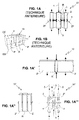
- the first approach ( patent application no. FR 2 962 614 published on January 13, 2012 on behalf of the applicant) is illustrated in the Figure 1A intended to explain the operation of the vibrating core 10 of the resonator, and to Figure 1B which shows a perspective view in longitudinal section of the resonator comprising the vibrating core 10 and a straight hollow cylinder CC of square directors surrounding the vibrating core 10 and intended to be assembled on a housing base EB.
- the vibrating core 10 of the resonator comprises a solid right cylinder R, a hollow right cylinder 2 of the same height surrounding the solid right cylinder, and a membrane 1 disposed in the median plane n and integral with the cylindrical surface of the solid cylinder and the inner cylindrical surface of the hollow cylinder.
- the solid cylinder R vibrates according to a longitudinal extension-compression resonance mode and has a vibration node N located in the median plane ⁇ , and the hollow cylinder 2 also vibrates in longitudinal extension-compression resonance mode, at the same frequency as the full cylinder, but in phase opposition with the vibration of the full cylinder.
- the identity of the resonance frequencies of the two cylinders comes from the identity of their heights, which is a necessary condition for the operation of the resonator (see page 9 line 37 to page 10 line 11 of the aforementioned patent).
- the anti-phase vibrations of the two cylinders correspond to a particular mechanical resonance mode of the vibrating core 10, that is to say to a spontaneous mode.
- the mass of the hollow cylinder 2 is much greater than the mass of the solid cylinder R, because the thickness of the wall of the hollow cylinder is of the order of magnitude of the diameter of the full cylinder (see page 12 line 2 to line 9). This geometrical condition implies that the mass of the hollow cylinder 2 is of the order of 10 times the mass of the solid cylinder R.
- the zone ZF can be almost decoupled from the vibration of the resonator, which allows, as shown in FIG. Figure 1B to hold the hollow cylinder 2 by means of P bridges integral with a hollow cylinder CC without altering the intrinsic quality coefficient of the resonator.
- the operation of this resonator known from the prior art is thus very satisfactory.
- the beams 2 ' In order to comply with the conditions recommended by the aforementioned patent, the beams 2 'should have the same height as the bar and a mass much greater than that of the bar, which would lead to the beams 2' to a very large dimension taken in the plan of the structure perpendicular to their height dimension, as illustrated in Figure 1A ' .
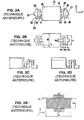
- the Figure 2A shows a front view of a contour vibration mode piezoelectric resonator 21 comprising a vibrating portion 26 and at least one support portion 25 forming a part with the vibrating portion by means of a bridge portion 31.
- the resonator 21 is characterized in that each support portion 25 consists of an elastic portion 30 interconnected with said vibrating portion 26, an attenuation portion 28 made of a piece with said elastic portion 30 and moving only in a minimal manner and a fixing portion 27 for attachment to a support member.
- the attenuation portion 28 is connected at both ends to the resilient portion 30 via connection portions 29, thereby forming a lumen in the support portion 25.
- the width of the bridge portion 31, the width of the elastic portion 30, the width of the attenuation portion 28, the distance between the elastic portion and the attenuation portion, and the length of the elastic portion are respectively W0 , W1, W2, W3 and L1, as shown in Figure 2B .
- FIGS. 2C and 2D show in dashed line the exaggeratedly enlarged deformations of the vibrating resonator on two contour modes respectively. It is specified that the resonator is provided to operate simultaneously on these two modes voluntarily coupled together, which is achieved by respecting certain dimensional ratios between the short side W and the long side L of the vibrating portion 26; this makes it possible to obtain an excellent frequency / temperature characteristic of the resonator.
- the disadvantage of this second approach concerns the difficulty of producing the resonator with sufficient accuracy to ensure proper operation. particularly at the level of the support portions 25 and more precisely with respect to the widths W1 and W2 of the elastic portion and the attenuation portion respectively, and the distance W3 between the elastic portion and the attenuation portion.
- This difficulty of realization all the greater as the dimensions of the resonator are small, is translated either by a brake to the miniaturization of the resonator, or by a relatively high manufacturing cost.
- the object of the invention is in particular to overcome the drawbacks of the earlier approaches by proposing a mechanical resonator whose operation is as satisfactory as that provided by the first and second approaches, but whose structure is better adapted to reducing congestion and the cost of the resonator.
- the mechanical resonator planar structure comprising a vibrating bar in an extension-compression resonance mode along its longitudinal central axis and having a vibration node in its median plane perpendicular to said longitudinal central axis, the vibration naturally inducing transverse extension-compression deformations, is characterized in that the structure comprises two parallelepipedal beams substantially identical to each other, each symmetrical with respect to said median plane and disposed respectively on either side of the bar, the axes longitudinals beams being parallel to said longitudinal central axis, the length of the beams being substantially equal to that of the bar and the slenderness of the beams taken in the plane of the structure being substantially equal to the result of the addition of six and a half and a number equal to twenty-eight percent of the slenderness of the bar taken in the plane of the structure, and two connecting elements respectively disposed of and else of the bar in the vicinity of said median plane and each connecting a face of the bar to a face of a
- the simultaneous vibrations of the bar in longitudinal extension-compression resonance mode and of the beams according to said first and second modes correspond to a particular mechanical resonance mode of the resonator structure according to the invention, for which the setting in vibration can be spontaneously obtained by exciting the bar in longitudinal extension-compression resonance mode.
- the first relationship length of the beams substantially equal to that of the bar
- the second relationship sinum thickness of the beams substantially equal to the result of the addition of six and a half and a number equal to twenty-eight percent of the slenderness of the bar
- the second relationship relates to the second mode and allows to work the beams in the vicinity of their bending resonance frequency.
- the two dimensional relationships condition the distribution of the transverse deformations of each of the beams coming from a part of said first longitudinal stretch-compression mode and secondly from said second bending mode, so that the effects of the overall transverse deformation of the beam compensates for the effects of the transverse deformations of the bar in said zone.
- the length and the slenderness of the beams allowing this compensation each have a single value.
- the resonator does not work if the second relationship is satisfied but not the first, because in this case there is no vibration of said first longitudinal extension-compression mode of the beams.
- said zone located on the face of each of the beams opposite to the integral face of the connecting element can be decoupled from the vibration of the bar and it is possible, by fixing the device on said zone, to obtain that the real quality coefficient of the bar is close to its large coefficient intrinsic quality.
- the resonator dimensioning is optimized for example by means of numerical simulations based on the finite element method.
- the resonator can be produced at very low cost by collective machining exclusively leading to a flat plate of uniform thickness material.
- the solid configuration of the resonator beams according to the invention allows the correct operation of the resonator to be less demanding as regards the precision of embodiment. .
- the resonator structure according to the invention is easier to produce, and therefore more favorable to reducing the cost and bulk of the resonator.
- the structure further comprises two fixing blocks disposed towards the outside of the structure and each connected to a beam by means of a connecting element disposed in the vicinity of said median plane, that is, that is to say in said zone, which allows that fixing of said blocks on a support does not alter the coefficient of quality of the resonator.
- the structure is made of quartz, the plane of the structure being parallel to the XY crystallographic plane and the longitudinal central axis of the bar being parallel to the crystallographic axis Y, and the structure is equipped with vibration setting acting by piezoelectric effect.
- the plane structure of mechanical resonator according to the third Embodiment is characterized in that the vibrating means comprise electrodes arranged on the faces of the bar and beams and extending parallel to the longitudinal central axis.
- planar mechanical resonator structure according to the fourth embodiment is characterized in that the structure is produced by chemical etching in sub-millimetric dimensions.
- planar mechanical resonator structure according to the fourth embodiment is characterized in that the structure is produced by reactive ion etching in sub-millimetric dimensions.
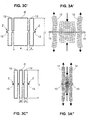
- FIG 3C shows a perspective view of a resonator 100 according to the invention.
- the structure of the resonator 100 is monolithic and made in a flat plate of material of uniform thickness b by means of machining exclusively opening; the structure is therefore well suited to integration techniques of micro systems.
- the material is advantageously chosen for its very low viscous damping; it may be for example an isotropic material such as silica, or a crystalline material such as quartz.
- the machining can be performed for example by reactive ion etching or by chemical etching.
- the resonator 100 comprises a parallelepipedal R bar whose longitudinal central axis ⁇ extends parallel to the plane of the plate and whose median plane n perpendicular to said central longitudinal axis ⁇ is perpendicular to the plane of the plate.
- the dimensions of the bar R taken in the plane of the plate are its length L and its width a; the slenderness of the bar R taken in the plane of the plate is therefore L / a. In the illustrated representation, said slenderness of the bar is substantially equal to 4.
- the resonator according to the invention does not impose a precise recommendation. It is simply necessary to ensure that the thickness b is not too low (which could induce parasitic vibration modes transverse to the plate) or too strong (Poisson effects transverse to the plate could hinder the proper functioning of the resonator ).
- the resonator according to the invention is well suited to a thickness b of the plate of the order of magnitude of the width c of the beams.
- the resonator 100 also comprises two connecting elements 11 disposed respectively on either side of the bar in the vicinity of said median plane and each connecting a machined face of the bar to a machined face of a beam.
- the resonator 100 also comprises two fixing blocks PF disposed towards the outside of the resonator and each connected to a beam 12 by means of a connecting element 13 disposed in the vicinity of the median plane ⁇ .
- the fixing blocks PF are intended to be assembled on an EB housing base (not shown).
- the figure 3A shows exaggeratedly enlarged deformations of the vibrating bar R according to an extension-compression resonance mode along its longitudinal central axis ⁇ and having a vibration node N in its median plane ⁇ , the vibration naturally inducing transverse extension-compression deformations due to the Poisson's ratio of the material and indicated in the figure by means of V-shaped arrows, said transverse deformations being maximum in the median plane ⁇ and zero at the ends of the bar.
- the bar R shown at figure 3A and its longitudinal extension-compression vibration naturally inducing transverse deformations are analogous to the full right R cylinder of the prior art shown in FIG. Figure 1A and its vibration.
- the beams 12 each vibrate simultaneously in two modes, the first mode being a longitudinal extension-compression mode in phase opposition with the vibration of the bar, the second mode being a bending mode (partial second) occurring parallel to the plane of the plate, the mechanical excitation of the beams being effected at the level of the connecting elements 11.
- the first relationship length of the beams substantially equal to that of the bar
- the second relation slenderness of the beams substantially equal to the result of the addition of six and a half and a number equal to twenty-eight percent of the slenderness of the bar
- the bending resonance frequency of the beams is about 10% higher than the frequency of the resonator.
- the two dimensional relationships condition the distribution of the transverse deformations of each of the beams coming from a part of said first longitudinal stretch-compression mode and secondly from said second bending mode, so that the effects of the overall transverse deformation of the beam compensates the effects of the transverse deformations of the bar in a zone Z situated on the face of the beam opposite to the integral face of the connecting element 11 and in the vicinity of the median plane ⁇ , as well as is explained in the following in relation to the figure 3B .
- the figure 3B shows the superposition of different states of the exaggeratedly enlarged deformation of a beam 12 during the half-period of the vibration of the resonator corresponding to the longitudinal compression of the bar.
- the beam deforms simultaneously in extension (said first mode) and in flexion (said second mode), and that its width dimension, initially c, undergoes an alternating variation during the vibration, said maximum variation being maximum at neighborhood of the median plane ⁇ and zero at the ends of the beam; said alternative variation results from the combination of two phenomena.
- the first phenomenon is the transverse deformation of the beam (Poisson effect) related to its longitudinal extension.
- the second phenomenon is the transverse deformation of the beam related to its bending and its mechanical excitation by the connecting element 11.
- the connecting elements 13 located in the zones Z can be completely decoupled from the vibration of the bar, and it is possible by fixing the vibrating core of the resonator at the level of said connecting elements, for example by means of the fixing blocks PF shown to the figure 3C to obtain that the real quality coefficient of the bar is close to its great intrinsic quality coefficient.
- the proper operation of the resonator according to the invention is less demanding on the accuracy of realization than the resonator according to the second approach illustrated in FIGS. Figures 2A and 2B .
- the support portions of the resonator according to the second approach comprise elements of relatively small dimensions (in particular the thicknesses W1 and W3 of the elastic portion 30 and the attenuation portion 28), which is not the case of the solid beams of the resonator according to the invention.
- the structure of the resonator according to the invention is better suited to reducing the size and the cost of the resonator.
- the expression "parallelepiped beam”, as used here, is to be considered in the broad sense, the important thing being that the operation of the resonator is similar to that just described.
- the face contour of the beams, rectangular in the figures illustrating the invention may have chamfers or roundings replacing sharp corners. This is not a disadvantage for the operation of the resonator according to the invention if care is taken to take these forms into account in the numerical simulations used to optimize the operation of the resonator.
- the Figure 3C ' shows a front view of the vibrating core of another resonator according to the invention, for which the slenderness L / a of the bar R is substantially equal to 2.
- the length of the beams 12 is substantially equal to the length L of the bar and their width c is such that the slenderness L / c of the beams is substantially the result of the addition of 6.5 and a number equal to 28% of the slenderness L / a of the bar; in this case, the slenderness of the beams is substantially:
- FIG. 3A which shows exaggeratedly enlarged deformations of this vibrating core, we see that the beams 12 each vibrate simultaneously in said first and second modes, and the results of the finite element numerical simulations indicate that the connecting elements 13 undergo substantially no displacement at during the vibration.
- the Figure 3C " shows a front view of the vibrating core of another resonator according to the invention, for which the slenderness L / a of the bar R is substantially equal to 10.
- the length of the beams 12 is substantially equal to the length L of the bar and their width c is such that the slenderness L / c of the beams is substantially the result of the addition of 6.5 and a number equal to 28% of the slenderness L / a of the bar; in this case, the slenderness of the beams is substantially:
- the resonator according to the invention is suitable for any slenderness of the bar.
- the extension-compression resonance frequency of the bar is substantially proportional to the magnitude 1 / L
- the bending resonance frequency of the beams is substantially proportional to the magnitude c / L 2 .
- the resonator according to the invention is well suited to miniaturization.
- quartz resonator of overall dimensions 500 ⁇ m ⁇ 500 ⁇ m ⁇ 50 ⁇ m whose frequency is of the order of 5 MHz and whose quality coefficient is greater than 10 6 .
- the Figure 4A shows the resonator 100 of the figure 3C whose bar R is equipped with electrodes 20 and 21 acting by piezoelectric effect.
- the electrodes 20 and 21 are disposed on each of the two faces of the flush bar R the large faces of the plate, and are in the form of ribbons extending parallel to the longitudinal axis ⁇ which is also the mechanical crystallographic axis Y of quartz.
- the Figure 4A shows the electrodes 20 and 21 on one of said faces of the bar; the electrodes 20 and 21 on the other side, indicated by means of a dotted reference line, are respectively arranged facing each other.
- the electrodes 20 and 21 are able to create in the bar an electric field whose component E X perpendicular to the longitudinal axis ⁇ and parallel to the large faces of the plate is coupled by piezoelectric effect to the mechanical stress of extension or compression T YY intervenes predominantly in the extension-compression vibration of the bar R.
- the electrodes 20 and 21 are effective means for vibrating the bar R.
- the beams 12 of the resonator 100 are also equipped with electrodes acting by piezoelectric effect and also referenced 20 and 21 to translate the identity of the polarities with the electrodes of the R bar.
- the arrangement of the electrodes of the beams 12 makes it possible to create in the beams an electric field whose component E X is opposite to that of the bar.
- the electrodes 20 and 21 are able to excite in the beams a longitudinal extension-compression vibration in phase opposition with the longitudinal extension-compression vibration of the bar.
- the electrodes 20 and 21 equipping the beams are not necessary for the operation of the resonator according to the invention, since the vibration of the bar is sufficient, mechanically, to vibrate the beams in phase opposition as explained previously. Nevertheless, the electrodes 20 and 21 equipping the beams are interesting because they make it possible to improve the piezoelectric coupling of the resonator.
- the electrodes 20 and 21 are connected to electrical connection pads 40 and 41, respectively, arranged on the fixing blocks PF, by means of connection strips 30 and 31 running on the connecting elements 11 and 13, the beams 12 and PF fixing blocks.
- the Figure 4B shows the resonator 100 equipped with electrodes 20 'and 21' more complete than the electrodes 20 and 21 of the Figure 4A .
- the electrodes 20 'and 21' comprise, in addition to strips disposed on the faces of the bar and beams flush with the two large faces of the plate, other strips arranged on the machined faces of the bar and the beams and made for example by evaporation of metal in oblique directions with respect to the main axes of the resonator, each of said other ribbons being in electrical contact with the ribbon of a large face flush with the common edge.
- the E X component of the electric field may be more intense, and the efficiency of the electrodes 20 'and 21' greater than that of the electrodes 20 and 21, however, with additional manufacturing costs.
- connection strips 30 and 31 and the connection pads 40 and 41 are provided by said other ribbons, it is no longer necessary to arrange the connection strips 30 and 31 and the connection pads 40 and 41 on the two large faces of the resonator .
Landscapes
- Physics & Mathematics (AREA)
- Acoustics & Sound (AREA)
- Piezo-Electric Or Mechanical Vibrators, Or Delay Or Filter Circuits (AREA)
Claims (6)
- Flache Struktur eines mechanischen Resonators (100), der einen Stab (R) umfasst, der gemäß einer Dehnungs-/Kompressionsfunktionsart entlang seiner Längsmittelachse (Δ) schwingt und einen Schwingungsknoten (N) in seiner Mittelebene (n) aufweist, die senkrecht zur Längsmittelachse ist, wobei die Schwingung auf natürliche Weise Dehnungs-/Kompressionsquerverformungen herbeiführt,
dadurch gekennzeichnet, dass die Struktur zwei zueinander im Wesentlichen identische quaderförmige Balken (12) umfasst, die jeweils in Bezug auf die Mittelebene (π) symmetrisch und auf einer bzw. der anderen Seite des Stabs (R) angeordnet sind, wobei die Längsachsen der Balken zur Längsmittelachse (Δ) parallel sind, wobei die Länge der Balken im Wesentlichen gleich der Länge (L) des Stabs ist und das Längenverhältnis (L/c) der Balken in der Ebene der Struktur im Wesentlichen gleich dem Ergebnis der Addition von sechseinhalb und einer Zahl ist, die achtundzwanzig Prozent des Längenverhältnisses (L/a) des Stabs in der Ebene der Struktur beträgt, und zwei Verbindungelemente (11) umfasst, die auf der einen bzw. der anderen Seite des Stabs in der Nachbarschaft der Mittelebene angeordnet sind und jeweils eine Seite des Stabs mit einer Seite eines Balkens verbinden, wodurch die Balken, die im Bereich der Verbindungselemente (11) durch die Dehnungs-/Kompressionsquerverformungen des Balkens angeregt werden, jeweils gleichzeitig gemäß zweier Funktionsarten schwingen, wobei die erste Funktionsart eine Längsdehnungs-Längskompressionsfunktionsart in Gegenphase zur Schwingung des Balkens ist, wobei die zweite Funktionsart eine Durchbiegungsfunktionsart ist, die parallel zur Ebene der Struktur erfolgt, und sich die Auswirkungen der Querverformungen des Stabs und jeweils der Balken in einer Zone (Z) ausgleichen, die sich auf der Seite des Balkens, die der mit dem Verbindungselement (11) fest verbundenen Seite gegenüberliegt, und in der Nachbarschaft der Mittelebene (n) befindet. - Flache Struktur eines mechanischen Resonators nach Anspruch 1, dadurch gekennzeichnet, dass die Struktur darüber hinaus zwei Fixierungsblöcke (PF) umfasst, die zum Äußeren der Struktur hin angeordnet und jeweils mittels eines in der Nachbarschaft der Mittelebene (π) angeordneten Verbindungselements (13) mit einem Balken (12) verbunden sind.
- Flache Struktur eines mechanischen Resonators nach einem der vorhergehenden Ansprüche, dadurch gekennzeichnet, dass die Struktur aus Quarz ist, wobei die Ebene der Struktur parallel zur kristallografischen Ebene XY ist, und wobei die Längsmittelachse (Δ) des Balkens parallel zur kristallografischen Ebene Y ist, und dass die Struktur mit Schwingungsbewirkungseinrichtungen ausgestattet ist, die durch piezoelektrischen Effekt wirken.
- Flache Struktur eines mechanischen Resonators nach Anspruch 3, dadurch gekennzeichnet, dass die Schwingungsbewirkungseinrichtungen Elektroden (20, 21; 20', 21`) umfassen, die an den Seiten des Balkens und der Stäbe vorgesehen sind und sich parallel zur Längsmittelachse (Δ) erstrecken.
- Flache Struktur eines mechanischen Resonators nach Anspruch 4, dadurch gekennzeichnet, dass die Struktur durch chemisches Ätzen in Submillimeterabmessungen hergestellt ist.
- Flache Struktur eines mechanischen Resonators nach Anspruch 4, dadurch gekennzeichnet, dass die Struktur durch reaktives Ionenätzen in Submillimeterabmessungen hergestellt ist.
Applications Claiming Priority (2)
| Application Number | Priority Date | Filing Date | Title |
|---|---|---|---|
| FR1300322A FR3002095B1 (fr) | 2013-02-14 | 2013-02-14 | Structure plane de resonateur mecanique decouple par des vibrations de flexion et d'extension-compression |
| PCT/FR2014/000037 WO2014125178A1 (fr) | 2013-02-14 | 2014-02-13 | Structure plane de résonateur mécanique découplé par des vibrations de flexion et d'extension-compression |
Publications (2)
| Publication Number | Publication Date |
|---|---|
| EP2957031A1 EP2957031A1 (de) | 2015-12-23 |
| EP2957031B1 true EP2957031B1 (de) | 2017-07-19 |
Family
ID=49378309
Family Applications (1)
| Application Number | Title | Priority Date | Filing Date |
|---|---|---|---|
| EP14711544.8A Active EP2957031B1 (de) | 2013-02-14 | 2014-02-13 | Flache struktur eines mechanischen resonators welcher durch biege- und dehnungsschwingungen entkoppelt ist |
Country Status (5)
| Country | Link |
|---|---|
| US (1) | US9484884B2 (de) |
| EP (1) | EP2957031B1 (de) |
| JP (1) | JP6400608B2 (de) |
| FR (1) | FR3002095B1 (de) |
| WO (1) | WO2014125178A1 (de) |
Families Citing this family (3)
| Publication number | Priority date | Publication date | Assignee | Title |
|---|---|---|---|---|
| FR3002095B1 (fr) * | 2013-02-14 | 2015-02-20 | Onera (Off Nat Aerospatiale) | Structure plane de resonateur mecanique decouple par des vibrations de flexion et d'extension-compression |
| WO2016051022A1 (en) * | 2014-10-03 | 2016-04-07 | Teknologian Tutkimuskeskus Vtt Oy | Temperature compensated beam resonator |
| FR3131141B1 (fr) | 2021-12-16 | 2023-11-10 | Office National Detudes Rech Aerospatiales | Structure plane de resonateur mecanique a vibration d'extension-compression selon un mode partiel egal a trois |
Family Cites Families (10)
| Publication number | Priority date | Publication date | Assignee | Title |
|---|---|---|---|---|
| DE2939844A1 (de) | 1978-12-21 | 1980-07-10 | Seiko Instr & Electronics | Quarzschwinger |
| JPH0821828B2 (ja) * | 1988-09-09 | 1996-03-04 | セイコー電子工業株式会社 | 縦水晶振動子 |
| JPH0831765B2 (ja) * | 1988-11-17 | 1996-03-27 | セイコー電子工業株式会社 | 縦水晶振動子 |
| DE4322144C2 (de) * | 1992-07-03 | 1997-06-05 | Murata Manufacturing Co | Vibratoreinheit |
| JPH0621743A (ja) * | 1992-07-03 | 1994-01-28 | Murata Mfg Co Ltd | 圧電共振子 |
| JPH08265093A (ja) * | 1995-03-22 | 1996-10-11 | Murata Mfg Co Ltd | チップ型圧電共振部品 |
| US7323952B2 (en) * | 2005-09-02 | 2008-01-29 | Robert Bosch Gmbh | Breath-mode ring resonator structure, and method of designing, operating and using same |
| US8040207B2 (en) * | 2009-01-15 | 2011-10-18 | Infineon Technologies Ag | MEMS resonator devices with a plurality of mass elements formed thereon |
| FR2962614B1 (fr) | 2010-07-06 | 2012-07-27 | Onera (Off Nat Aerospatiale) | Module de decouplage mecanique d'un resonateur a grand coefficient de qualite |
| FR3002095B1 (fr) * | 2013-02-14 | 2015-02-20 | Onera (Off Nat Aerospatiale) | Structure plane de resonateur mecanique decouple par des vibrations de flexion et d'extension-compression |
-
2013
- 2013-02-14 FR FR1300322A patent/FR3002095B1/fr not_active Expired - Fee Related
-
2014
- 2014-02-13 US US14/767,082 patent/US9484884B2/en active Active
- 2014-02-13 JP JP2015557489A patent/JP6400608B2/ja active Active
- 2014-02-13 EP EP14711544.8A patent/EP2957031B1/de active Active
- 2014-02-13 WO PCT/FR2014/000037 patent/WO2014125178A1/fr not_active Ceased
Non-Patent Citations (1)
| Title |
|---|
| None * |
Also Published As
| Publication number | Publication date |
|---|---|
| WO2014125178A9 (fr) | 2015-07-23 |
| US20160006412A1 (en) | 2016-01-07 |
| EP2957031A1 (de) | 2015-12-23 |
| FR3002095A1 (fr) | 2014-08-15 |
| JP2016513406A (ja) | 2016-05-12 |
| JP6400608B2 (ja) | 2018-10-03 |
| WO2014125178A1 (fr) | 2014-08-21 |
| FR3002095B1 (fr) | 2015-02-20 |
| US9484884B2 (en) | 2016-11-01 |
Similar Documents
| Publication | Publication Date | Title |
|---|---|---|
| EP2441170B1 (de) | Electromechanischer resonator mit resonierender aufhängung | |
| EP2909932B1 (de) | Wandler mit durch synchrone anregungsstrukturen geführten volumenwellen | |
| FR2835981A1 (fr) | Microresonateur mems a ondes acoustiques de volume accordable | |
| EP2960625A1 (de) | Winkelförmiger mems-trägheitssensor, der im stimmgabelmodus betrieben wird | |
| EP1633042A1 (de) | Quartzresonator mit sehr kleinen Abmessungen | |
| EP1672315B1 (de) | Wandler zur Winkelgeschwindigkeitsmessung | |
| EP0334705B1 (de) | Resonatoren aus hartem. elastischem Material und sehr stabile Oszillatoren | |
| WO2014125178A1 (fr) | Structure plane de résonateur mécanique découplé par des vibrations de flexion et d'extension-compression | |
| EP2414774B1 (de) | In zwei entkoppelten modi schwingendes element und verwendung in einem schwingkreisel | |
| EP2351214A1 (de) | Körperwellenfilterelemente mittels querkopplung an resonante strukturen mit mehreren harmonischen resonanzen | |
| EP3491371B1 (de) | Optimierter mechanischer resonator zum betrieb in einer flüssigkeit | |
| EP0350443B1 (de) | Piezoelektrischer Resonator | |
| EP1151246B1 (de) | Monolithische struktur eines schwingungs-gyroskops | |
| EP2591549B1 (de) | Modul zur mechanischen abkopplung eines resonators mit hohem qualitätsfaktor | |
| EP1625659B1 (de) | Integrierte resonatoren und zeitbasis mit solchen resonatoren | |
| EP2878573B1 (de) | Masse-Feder-System mit schwacher Querauslenkung | |
| EP4305752B1 (de) | Biegeschwingungsresonator mit hohem qualitätsfaktor für die herstellung von zeitnormalen, kraftsensoren oder gyrometern | |
| FR2624326A1 (fr) | Resonateur piezoelectrique | |
| EP1235074A1 (de) | Miniaturisierter Beschleunigungsmesser mit zwei Masse-Zellen | |
| EP0451089B1 (de) | Hochfrequenter piezoelektrischer Schwinger | |
| EP4576573A1 (de) | Haltevorrichtung für piezoelektrischen resonator und stromwandler damit | |
| FR2662032A1 (fr) | Resonateur comportant un barreau destine a vibrer dans un mode d'allongement. | |
| FR2824909A1 (fr) | Capteur de force a poutre vibrante et accelerometre en faisant application | |
| FR3025673A1 (fr) | Resonateur mecanique vibrant en flexion |
Legal Events
| Date | Code | Title | Description |
|---|---|---|---|
| PUAI | Public reference made under article 153(3) epc to a published international application that has entered the european phase |
Free format text: ORIGINAL CODE: 0009012 |
|
| 17P | Request for examination filed |
Effective date: 20150805 |
|
| AK | Designated contracting states |
Kind code of ref document: A1 Designated state(s): AL AT BE BG CH CY CZ DE DK EE ES FI FR GB GR HR HU IE IS IT LI LT LU LV MC MK MT NL NO PL PT RO RS SE SI SK SM TR |
|
| AX | Request for extension of the european patent |
Extension state: BA ME |
|
| DAX | Request for extension of the european patent (deleted) | ||
| GRAP | Despatch of communication of intention to grant a patent |
Free format text: ORIGINAL CODE: EPIDOSNIGR1 |
|
| RIC1 | Information provided on ipc code assigned before grant |
Ipc: H03H 9/15 20060101ALN20170203BHEP Ipc: H03H 9/24 20060101ALI20170203BHEP Ipc: H03H 9/02 20060101AFI20170203BHEP Ipc: H03H 9/205 20060101ALN20170203BHEP |
|
| INTG | Intention to grant announced |
Effective date: 20170309 |
|
| GRAS | Grant fee paid |
Free format text: ORIGINAL CODE: EPIDOSNIGR3 |
|
| GRAA | (expected) grant |
Free format text: ORIGINAL CODE: 0009210 |
|
| AK | Designated contracting states |
Kind code of ref document: B1 Designated state(s): AL AT BE BG CH CY CZ DE DK EE ES FI FR GB GR HR HU IE IS IT LI LT LU LV MC MK MT NL NO PL PT RO RS SE SI SK SM TR |
|
| RAP1 | Party data changed (applicant data changed or rights of an application transferred) |
Owner name: OFFICE NATIONAL D'ETUDES ET DE RECHERCHES AEROSPAT |
|
| REG | Reference to a national code |
Ref country code: GB Ref legal event code: FG4D Free format text: NOT ENGLISH |
|
| REG | Reference to a national code |
Ref country code: CH Ref legal event code: EP |
|
| REG | Reference to a national code |
Ref country code: IE Ref legal event code: FG4D Free format text: LANGUAGE OF EP DOCUMENT: FRENCH |
|
| REG | Reference to a national code |
Ref country code: AT Ref legal event code: REF Ref document number: 911308 Country of ref document: AT Kind code of ref document: T Effective date: 20170815 |
|
| REG | Reference to a national code |
Ref country code: DE Ref legal event code: R096 Ref document number: 602014011958 Country of ref document: DE |
|
| REG | Reference to a national code |
Ref country code: CH Ref legal event code: NV Representative=s name: RIEDERER HASLER AND PARTNER PATENTANWAELTE AG, CH |
|
| REG | Reference to a national code |
Ref country code: NL Ref legal event code: MP Effective date: 20170719 |
|
| REG | Reference to a national code |
Ref country code: LT Ref legal event code: MG4D |
|
| REG | Reference to a national code |
Ref country code: AT Ref legal event code: MK05 Ref document number: 911308 Country of ref document: AT Kind code of ref document: T Effective date: 20170719 |
|
| REG | Reference to a national code |
Ref country code: FR Ref legal event code: PLFP Year of fee payment: 5 |
|
| PG25 | Lapsed in a contracting state [announced via postgrant information from national office to epo] |
Ref country code: AT Free format text: LAPSE BECAUSE OF FAILURE TO SUBMIT A TRANSLATION OF THE DESCRIPTION OR TO PAY THE FEE WITHIN THE PRESCRIBED TIME-LIMIT Effective date: 20170719 Ref country code: NO Free format text: LAPSE BECAUSE OF FAILURE TO SUBMIT A TRANSLATION OF THE DESCRIPTION OR TO PAY THE FEE WITHIN THE PRESCRIBED TIME-LIMIT Effective date: 20171019 Ref country code: HR Free format text: LAPSE BECAUSE OF FAILURE TO SUBMIT A TRANSLATION OF THE DESCRIPTION OR TO PAY THE FEE WITHIN THE PRESCRIBED TIME-LIMIT Effective date: 20170719 Ref country code: LT Free format text: LAPSE BECAUSE OF FAILURE TO SUBMIT A TRANSLATION OF THE DESCRIPTION OR TO PAY THE FEE WITHIN THE PRESCRIBED TIME-LIMIT Effective date: 20170719 Ref country code: FI Free format text: LAPSE BECAUSE OF FAILURE TO SUBMIT A TRANSLATION OF THE DESCRIPTION OR TO PAY THE FEE WITHIN THE PRESCRIBED TIME-LIMIT Effective date: 20170719 Ref country code: SE Free format text: LAPSE BECAUSE OF FAILURE TO SUBMIT A TRANSLATION OF THE DESCRIPTION OR TO PAY THE FEE WITHIN THE PRESCRIBED TIME-LIMIT Effective date: 20170719 Ref country code: NL Free format text: LAPSE BECAUSE OF FAILURE TO SUBMIT A TRANSLATION OF THE DESCRIPTION OR TO PAY THE FEE WITHIN THE PRESCRIBED TIME-LIMIT Effective date: 20170719 |
|
| PG25 | Lapsed in a contracting state [announced via postgrant information from national office to epo] |
Ref country code: PL Free format text: LAPSE BECAUSE OF FAILURE TO SUBMIT A TRANSLATION OF THE DESCRIPTION OR TO PAY THE FEE WITHIN THE PRESCRIBED TIME-LIMIT Effective date: 20170719 Ref country code: IS Free format text: LAPSE BECAUSE OF FAILURE TO SUBMIT A TRANSLATION OF THE DESCRIPTION OR TO PAY THE FEE WITHIN THE PRESCRIBED TIME-LIMIT Effective date: 20171119 Ref country code: GR Free format text: LAPSE BECAUSE OF FAILURE TO SUBMIT A TRANSLATION OF THE DESCRIPTION OR TO PAY THE FEE WITHIN THE PRESCRIBED TIME-LIMIT Effective date: 20171020 Ref country code: LV Free format text: LAPSE BECAUSE OF FAILURE TO SUBMIT A TRANSLATION OF THE DESCRIPTION OR TO PAY THE FEE WITHIN THE PRESCRIBED TIME-LIMIT Effective date: 20170719 Ref country code: BG Free format text: LAPSE BECAUSE OF FAILURE TO SUBMIT A TRANSLATION OF THE DESCRIPTION OR TO PAY THE FEE WITHIN THE PRESCRIBED TIME-LIMIT Effective date: 20171019 Ref country code: ES Free format text: LAPSE BECAUSE OF FAILURE TO SUBMIT A TRANSLATION OF THE DESCRIPTION OR TO PAY THE FEE WITHIN THE PRESCRIBED TIME-LIMIT Effective date: 20170719 Ref country code: RS Free format text: LAPSE BECAUSE OF FAILURE TO SUBMIT A TRANSLATION OF THE DESCRIPTION OR TO PAY THE FEE WITHIN THE PRESCRIBED TIME-LIMIT Effective date: 20170719 |
|
| REG | Reference to a national code |
Ref country code: DE Ref legal event code: R097 Ref document number: 602014011958 Country of ref document: DE |
|
| PG25 | Lapsed in a contracting state [announced via postgrant information from national office to epo] |
Ref country code: RO Free format text: LAPSE BECAUSE OF FAILURE TO SUBMIT A TRANSLATION OF THE DESCRIPTION OR TO PAY THE FEE WITHIN THE PRESCRIBED TIME-LIMIT Effective date: 20170719 Ref country code: DK Free format text: LAPSE BECAUSE OF FAILURE TO SUBMIT A TRANSLATION OF THE DESCRIPTION OR TO PAY THE FEE WITHIN THE PRESCRIBED TIME-LIMIT Effective date: 20170719 Ref country code: CZ Free format text: LAPSE BECAUSE OF FAILURE TO SUBMIT A TRANSLATION OF THE DESCRIPTION OR TO PAY THE FEE WITHIN THE PRESCRIBED TIME-LIMIT Effective date: 20170719 |
|
| PLBE | No opposition filed within time limit |
Free format text: ORIGINAL CODE: 0009261 |
|
| STAA | Information on the status of an ep patent application or granted ep patent |
Free format text: STATUS: NO OPPOSITION FILED WITHIN TIME LIMIT |
|
| PG25 | Lapsed in a contracting state [announced via postgrant information from national office to epo] |
Ref country code: IT Free format text: LAPSE BECAUSE OF FAILURE TO SUBMIT A TRANSLATION OF THE DESCRIPTION OR TO PAY THE FEE WITHIN THE PRESCRIBED TIME-LIMIT Effective date: 20170719 Ref country code: SK Free format text: LAPSE BECAUSE OF FAILURE TO SUBMIT A TRANSLATION OF THE DESCRIPTION OR TO PAY THE FEE WITHIN THE PRESCRIBED TIME-LIMIT Effective date: 20170719 Ref country code: SM Free format text: LAPSE BECAUSE OF FAILURE TO SUBMIT A TRANSLATION OF THE DESCRIPTION OR TO PAY THE FEE WITHIN THE PRESCRIBED TIME-LIMIT Effective date: 20170719 Ref country code: EE Free format text: LAPSE BECAUSE OF FAILURE TO SUBMIT A TRANSLATION OF THE DESCRIPTION OR TO PAY THE FEE WITHIN THE PRESCRIBED TIME-LIMIT Effective date: 20170719 |
|
| 26N | No opposition filed |
Effective date: 20180420 |
|
| PG25 | Lapsed in a contracting state [announced via postgrant information from national office to epo] |
Ref country code: SI Free format text: LAPSE BECAUSE OF FAILURE TO SUBMIT A TRANSLATION OF THE DESCRIPTION OR TO PAY THE FEE WITHIN THE PRESCRIBED TIME-LIMIT Effective date: 20170719 |
|
| PG25 | Lapsed in a contracting state [announced via postgrant information from national office to epo] |
Ref country code: MT Free format text: LAPSE BECAUSE OF FAILURE TO SUBMIT A TRANSLATION OF THE DESCRIPTION OR TO PAY THE FEE WITHIN THE PRESCRIBED TIME-LIMIT Effective date: 20170719 Ref country code: MC Free format text: LAPSE BECAUSE OF FAILURE TO SUBMIT A TRANSLATION OF THE DESCRIPTION OR TO PAY THE FEE WITHIN THE PRESCRIBED TIME-LIMIT Effective date: 20170719 |
|
| REG | Reference to a national code |
Ref country code: IE Ref legal event code: MM4A |
|
| REG | Reference to a national code |
Ref country code: BE Ref legal event code: MM Effective date: 20180228 |
|
| PG25 | Lapsed in a contracting state [announced via postgrant information from national office to epo] |
Ref country code: LU Free format text: LAPSE BECAUSE OF NON-PAYMENT OF DUE FEES Effective date: 20180213 |
|
| PG25 | Lapsed in a contracting state [announced via postgrant information from national office to epo] |
Ref country code: IE Free format text: LAPSE BECAUSE OF NON-PAYMENT OF DUE FEES Effective date: 20180213 |
|
| PG25 | Lapsed in a contracting state [announced via postgrant information from national office to epo] |
Ref country code: BE Free format text: LAPSE BECAUSE OF NON-PAYMENT OF DUE FEES Effective date: 20180228 |
|
| PG25 | Lapsed in a contracting state [announced via postgrant information from national office to epo] |
Ref country code: TR Free format text: LAPSE BECAUSE OF FAILURE TO SUBMIT A TRANSLATION OF THE DESCRIPTION OR TO PAY THE FEE WITHIN THE PRESCRIBED TIME-LIMIT Effective date: 20170719 |
|
| PG25 | Lapsed in a contracting state [announced via postgrant information from national office to epo] |
Ref country code: PT Free format text: LAPSE BECAUSE OF FAILURE TO SUBMIT A TRANSLATION OF THE DESCRIPTION OR TO PAY THE FEE WITHIN THE PRESCRIBED TIME-LIMIT Effective date: 20170719 |
|
| PG25 | Lapsed in a contracting state [announced via postgrant information from national office to epo] |
Ref country code: CY Free format text: LAPSE BECAUSE OF FAILURE TO SUBMIT A TRANSLATION OF THE DESCRIPTION OR TO PAY THE FEE WITHIN THE PRESCRIBED TIME-LIMIT Effective date: 20170719 Ref country code: HU Free format text: LAPSE BECAUSE OF FAILURE TO SUBMIT A TRANSLATION OF THE DESCRIPTION OR TO PAY THE FEE WITHIN THE PRESCRIBED TIME-LIMIT; INVALID AB INITIO Effective date: 20140213 Ref country code: MK Free format text: LAPSE BECAUSE OF NON-PAYMENT OF DUE FEES Effective date: 20170719 |
|
| PG25 | Lapsed in a contracting state [announced via postgrant information from national office to epo] |
Ref country code: AL Free format text: LAPSE BECAUSE OF FAILURE TO SUBMIT A TRANSLATION OF THE DESCRIPTION OR TO PAY THE FEE WITHIN THE PRESCRIBED TIME-LIMIT Effective date: 20170719 |
|
| REG | Reference to a national code |
Ref country code: CH Ref legal event code: U11 Free format text: ST27 STATUS EVENT CODE: U-0-0-U10-U11 (AS PROVIDED BY THE NATIONAL OFFICE) Effective date: 20260331 |
|
| PGFP | Annual fee paid to national office [announced via postgrant information from national office to epo] |
Ref country code: GB Payment date: 20260225 Year of fee payment: 13 |
|
| PGFP | Annual fee paid to national office [announced via postgrant information from national office to epo] |
Ref country code: DE Payment date: 20260324 Year of fee payment: 13 |
|
| PGFP | Annual fee paid to national office [announced via postgrant information from national office to epo] |
Ref country code: FR Payment date: 20260227 Year of fee payment: 13 |
|
| PGFP | Annual fee paid to national office [announced via postgrant information from national office to epo] |
Ref country code: CH Payment date: 20260331 Year of fee payment: 13 |