EP0898327A2 - Connecteur de carte de circuits - Google Patents
Connecteur de carte de circuits Download PDFInfo
- Publication number
- EP0898327A2 EP0898327A2 EP98115726A EP98115726A EP0898327A2 EP 0898327 A2 EP0898327 A2 EP 0898327A2 EP 98115726 A EP98115726 A EP 98115726A EP 98115726 A EP98115726 A EP 98115726A EP 0898327 A2 EP0898327 A2 EP 0898327A2
- Authority
- EP
- European Patent Office
- Prior art keywords
- circuit board
- printed circuit
- socket housing
- socket
- insulating body
- Prior art date
- Legal status (The legal status is an assumption and is not a legal conclusion. Google has not performed a legal analysis and makes no representation as to the accuracy of the status listed.)
- Granted
Links
- 238000000034 method Methods 0.000 claims abstract description 14
- 239000002184 metal Substances 0.000 claims abstract description 10
- 239000004020 conductor Substances 0.000 claims abstract description 5
- 238000005476 soldering Methods 0.000 abstract description 5
- 229910000679 solder Inorganic materials 0.000 description 4
- 238000003780 insertion Methods 0.000 description 3
- 230000037431 insertion Effects 0.000 description 3
- 239000012212 insulator Substances 0.000 description 3
- NMWSKOLWZZWHPL-UHFFFAOYSA-N 3-chlorobiphenyl Chemical compound ClC1=CC=CC(C=2C=CC=CC=2)=C1 NMWSKOLWZZWHPL-UHFFFAOYSA-N 0.000 description 2
- 101001082832 Saccharomyces cerevisiae (strain ATCC 204508 / S288c) Pyruvate carboxylase 2 Proteins 0.000 description 2
- 238000005516 engineering process Methods 0.000 description 2
- 238000005452 bending Methods 0.000 description 1
- 238000004870 electrical engineering Methods 0.000 description 1
- 238000004519 manufacturing process Methods 0.000 description 1
- 230000013011 mating Effects 0.000 description 1
- 230000002787 reinforcement Effects 0.000 description 1
Images


Classifications
-
- H—ELECTRICITY
- H01—ELECTRIC ELEMENTS
- H01R—ELECTRICALLY-CONDUCTIVE CONNECTIONS; STRUCTURAL ASSOCIATIONS OF A PLURALITY OF MUTUALLY-INSULATED ELECTRICAL CONNECTING ELEMENTS; COUPLING DEVICES; CURRENT COLLECTORS
- H01R12/00—Structural associations of a plurality of mutually-insulated electrical connecting elements, specially adapted for printed circuits, e.g. printed circuit boards [PCB], flat or ribbon cables, or like generally planar structures, e.g. terminal strips, terminal blocks; Coupling devices specially adapted for printed circuits, flat or ribbon cables, or like generally planar structures; Terminals specially adapted for contact with, or insertion into, printed circuits, flat or ribbon cables, or like generally planar structures
- H01R12/70—Coupling devices
- H01R12/7005—Guiding, mounting, polarizing or locking means; Extractors
- H01R12/7011—Locking or fixing a connector to a PCB
- H01R12/7052—Locking or fixing a connector to a PCB characterised by the locating members
-
- H—ELECTRICITY
- H01—ELECTRIC ELEMENTS
- H01R—ELECTRICALLY-CONDUCTIVE CONNECTIONS; STRUCTURAL ASSOCIATIONS OF A PLURALITY OF MUTUALLY-INSULATED ELECTRICAL CONNECTING ELEMENTS; COUPLING DEVICES; CURRENT COLLECTORS
- H01R12/00—Structural associations of a plurality of mutually-insulated electrical connecting elements, specially adapted for printed circuits, e.g. printed circuit boards [PCB], flat or ribbon cables, or like generally planar structures, e.g. terminal strips, terminal blocks; Coupling devices specially adapted for printed circuits, flat or ribbon cables, or like generally planar structures; Terminals specially adapted for contact with, or insertion into, printed circuits, flat or ribbon cables, or like generally planar structures
- H01R12/70—Coupling devices
- H01R12/7005—Guiding, mounting, polarizing or locking means; Extractors
- H01R12/7011—Locking or fixing a connector to a PCB
- H01R12/707—Soldering or welding
-
- H—ELECTRICITY
- H01—ELECTRIC ELEMENTS
- H01R—ELECTRICALLY-CONDUCTIVE CONNECTIONS; STRUCTURAL ASSOCIATIONS OF A PLURALITY OF MUTUALLY-INSULATED ELECTRICAL CONNECTING ELEMENTS; COUPLING DEVICES; CURRENT COLLECTORS
- H01R12/00—Structural associations of a plurality of mutually-insulated electrical connecting elements, specially adapted for printed circuits, e.g. printed circuit boards [PCB], flat or ribbon cables, or like generally planar structures, e.g. terminal strips, terminal blocks; Coupling devices specially adapted for printed circuits, flat or ribbon cables, or like generally planar structures; Terminals specially adapted for contact with, or insertion into, printed circuits, flat or ribbon cables, or like generally planar structures
- H01R12/50—Fixed connections
- H01R12/51—Fixed connections for rigid printed circuits or like structures
- H01R12/55—Fixed connections for rigid printed circuits or like structures characterised by the terminals
- H01R12/57—Fixed connections for rigid printed circuits or like structures characterised by the terminals surface mounting terminals
-
- H—ELECTRICITY
- H01—ELECTRIC ELEMENTS
- H01R—ELECTRICALLY-CONDUCTIVE CONNECTIONS; STRUCTURAL ASSOCIATIONS OF A PLURALITY OF MUTUALLY-INSULATED ELECTRICAL CONNECTING ELEMENTS; COUPLING DEVICES; CURRENT COLLECTORS
- H01R12/00—Structural associations of a plurality of mutually-insulated electrical connecting elements, specially adapted for printed circuits, e.g. printed circuit boards [PCB], flat or ribbon cables, or like generally planar structures, e.g. terminal strips, terminal blocks; Coupling devices specially adapted for printed circuits, flat or ribbon cables, or like generally planar structures; Terminals specially adapted for contact with, or insertion into, printed circuits, flat or ribbon cables, or like generally planar structures
- H01R12/70—Coupling devices
- H01R12/71—Coupling devices for rigid printing circuits or like structures
- H01R12/72—Coupling devices for rigid printing circuits or like structures coupling with the edge of the rigid printed circuits or like structures
- H01R12/722—Coupling devices for rigid printing circuits or like structures coupling with the edge of the rigid printed circuits or like structures coupling devices mounted on the edge of the printed circuits
- H01R12/725—Coupling devices for rigid printing circuits or like structures coupling with the edge of the rigid printed circuits or like structures coupling devices mounted on the edge of the printed circuits containing contact members presenting a contact carrying strip, e.g. edge-like strip
-
- H—ELECTRICITY
- H01—ELECTRIC ELEMENTS
- H01R—ELECTRICALLY-CONDUCTIVE CONNECTIONS; STRUCTURAL ASSOCIATIONS OF A PLURALITY OF MUTUALLY-INSULATED ELECTRICAL CONNECTING ELEMENTS; COUPLING DEVICES; CURRENT COLLECTORS
- H01R43/00—Apparatus or processes specially adapted for manufacturing, assembling, maintaining, or repairing of line connectors or current collectors or for joining electric conductors
- H01R43/20—Apparatus or processes specially adapted for manufacturing, assembling, maintaining, or repairing of line connectors or current collectors or for joining electric conductors for assembling or disassembling contact members with insulating base, case or sleeve
- H01R43/205—Apparatus or processes specially adapted for manufacturing, assembling, maintaining, or repairing of line connectors or current collectors or for joining electric conductors for assembling or disassembling contact members with insulating base, case or sleeve with a panel or printed circuit board
Definitions
- the invention relates to a printed circuit board socket with a fixable on a circuit board, in Cross section rectangular metal socket housing and one in it Socket housing used, a correspondingly rectangular Cross-section insulating body, the four according to the USB concept standardized, side by side in one level, has signal contacts designed as contact springs, which at Insert the bus connector with the four side by side provided in it Counter contacts interact and the electrical Make contact and face downward Connection ends can be connected to the contact points on the circuit board are.
- a known circuit board socket of this type (DE 296 02 268 U1) is the socket housing with its lower Housing wall directly on the circuit board.
- both the shield contacts of the socket housing and the four adjacent signal contacts as being rectangular Soldering pins extending to the lower housing wall, in the solder contact holes of the associated circuit board introduced and in it according to the solder wave process from below to be soldered.
- USB circuit board sockets compared to known fixing method described above easier and safer to be determined on printed circuit boards.
- the invention is therefore based on the object much simpler and still secure definition and connection of USB circuit board sockets on the circuit boards with only one soldering process.
- each tab has a punched hole with one on the edge of the hole molded collar facing the circuit board, which engages in an opening of the circuit board.
- This collar becomes horizontal insertion forces in a particularly simple way Form positively added to the circuit board.
- connection ends on the circuit board in a further embodiment of the invention thereby ensuring that the insulating body on its underside one in the recess of the socket housing with preferably five molded-in webs protruding reinforced body area and that the terminal ends of the contact springs are provided between these webs.
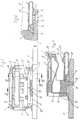
- the circuit board socket a rectangular in cross section, a shield Forming metal socket housing 1, which on a circuit board 2nd can be fixed, and one inserted into the socket housing 1, an insulating body having a corresponding rectangular cross section 3 includes.
- this insulating body 3 are four after USB concept standardized, lying next to each other on one level Signal contacts 4 designed as contact springs are used. These act when the - not shown - Bus connector with the four side by side provided in this Contacts together and make the electrical Contact her; They are via downward connection ends 4 can be connected to the contact points 6 of the printed circuit board 2.
- the metal bushing housing illustrated particularly clearly in FIG. 8 1 is a stamped and bent part made of a sheet metal strip manufactured. It comprises four bending edges 7 which on the one hand the two narrow sides of the housing 8 and on the other hand the upper housing wall 9 and with the two facing each other, half the side panels 10 'and 10' 'the bottom of the case 10 form.
- This housing base 10 of the metal socket housing 1 is over a distance to the circuit board 2 supporting and Connection areas 11 ', 11' 'with the printed circuit board 2 mechanically firmly connectable.
- a recess 12 which can be seen particularly well in FIG.
- connection ends 5 of the four signal contacts 4 to those not shown associated conductor tracks of the circuit board 2 extend.
- the the Ensuring the distance between the socket housing 1 and the printed circuit board 2 Support and connection areas are each separated by a from the lower front edge of the socket housing 1 in the area of two side parts 10 ', 10' 'of the housing base 10 outgoing to about 180 ° downward and backward bent fixing tabs 11 ', 11 '' formed.
- each of these fixing lugs 11 ', 11' ' is in each case a fastening zone 14 assigned to the circuit board 2.
- 6 and 8 show particularly clearly that each fixing tab 11 ', 11' 'a punched-out bore 15 with a molded on the edge of the bore, has the collar 16 facing the circuit board 16.
- the collar are each in a bore 17 of the mounting zone 14 of the PCB 2 insertable. This makes it a particularly safe one Positioning of the metal sleeve housing in relation to the PCB 2 guaranteed.
- the insulating body is on its underside 3 provided with a reinforced body area 18, which protrudes into the recess 12 of the socket housing 1. He comprises five integrally formed webs 19 which support the reinforcement. Between these are the connection ends 5 with the SMT contacts 13 of the signal contacts 4 are provided.
- the insulating body 3 Under the bottom is the insulating body 3 with at least provided two transversely projecting guide pins 20 which in engage recesses 21 of the printed circuit board 2 assigned to them.
- the position of the insulator 3 in Socket housing 1 inserted state serve lateral recesses 23 with the front boundary edge 24, behind the the insertion into the socket housing 1 each from the Narrow housing sides 8 punched latching tongue 25 snaps into place.
Landscapes
- Coupling Device And Connection With Printed Circuit (AREA)
- Multi-Conductor Connections (AREA)
Applications Claiming Priority (2)
| Application Number | Priority Date | Filing Date | Title |
|---|---|---|---|
| DE19736607 | 1997-08-22 | ||
| DE19736607A DE19736607C1 (de) | 1997-08-22 | 1997-08-22 | Leiterplattensteckbuchse |
Publications (3)
| Publication Number | Publication Date |
|---|---|
| EP0898327A2 true EP0898327A2 (fr) | 1999-02-24 |
| EP0898327A3 EP0898327A3 (fr) | 2000-08-30 |
| EP0898327B1 EP0898327B1 (fr) | 2003-01-15 |
Family
ID=7839871
Family Applications (1)
| Application Number | Title | Priority Date | Filing Date |
|---|---|---|---|
| EP98115726A Expired - Lifetime EP0898327B1 (fr) | 1997-08-22 | 1998-08-20 | Connecteur de carte de circuits |
Country Status (8)
| Country | Link |
|---|---|
| US (1) | US5928035A (fr) |
| EP (1) | EP0898327B1 (fr) |
| JP (1) | JPH11149964A (fr) |
| KR (1) | KR19990023687A (fr) |
| DE (1) | DE19736607C1 (fr) |
| ES (1) | ES2135365T1 (fr) |
| SG (1) | SG65783A1 (fr) |
| TW (1) | TW392380B (fr) |
Cited By (4)
| Publication number | Priority date | Publication date | Assignee | Title |
|---|---|---|---|---|
| WO2007064998A1 (fr) * | 2005-12-01 | 2007-06-07 | Molex Incorporated | Capot de blindage de connecteur |
| CN104577437A (zh) * | 2013-10-24 | 2015-04-29 | 日本航空电子工业株式会社 | 无需在金属外壳中形成大的开口却可以容易地获得期望的摩擦锁定的插座连接器 |
| CN105517885A (zh) * | 2013-10-21 | 2016-04-20 | 松下知识产权经营株式会社 | 车辆用操作装置及自行车 |
| CN109088215A (zh) * | 2018-08-03 | 2018-12-25 | 深圳市长盈精密技术股份有限公司 | 防水正反插usb插座 |
Families Citing this family (50)
| Publication number | Priority date | Publication date | Assignee | Title |
|---|---|---|---|---|
| US6270374B1 (en) * | 1998-01-20 | 2001-08-07 | Berg Technology, Inc. | Electrical connector with wafer for video positioning and surface mount holding feature |
| JP2000223216A (ja) * | 1999-01-27 | 2000-08-11 | Mitsumi Electric Co Ltd | 小型コネクタ |
| JP2000223191A (ja) * | 1999-01-27 | 2000-08-11 | Mitsumi Electric Co Ltd | 小型コネクタ |
| TW417872U (en) * | 1999-05-15 | 2001-01-01 | Hon Hai Prec Ind Co Ltd | Electrical connector |
| US6276965B1 (en) * | 1999-05-25 | 2001-08-21 | 3Com Corporation | Shielded I/O connector for compact communications device |
| JP2000357550A (ja) * | 1999-06-15 | 2000-12-26 | Fujitsu Takamisawa Component Ltd | 金属板を折り込んで形成された金属板製シェルを有するコネクタ |
| DE29912210U1 (de) | 1999-07-13 | 1999-09-16 | Leopold Kostal GmbH & Co KG, 58507 Lüdenscheid | Elektrische Steckverbinderanordnung |
| USD434382S (en) * | 1999-08-09 | 2000-11-28 | Hosiden Corporation | Electrical connecting socket |
| DE19939582A1 (de) * | 1999-08-20 | 2001-03-29 | Tyco Electronics Logistics Ag | Zur Montage auf eine Leiterplatte ausgelegtes Bauteil |
| US6517382B2 (en) * | 1999-12-01 | 2003-02-11 | Tyco Electronics Corporation | Pluggable module and receptacle |
| TW523194U (en) * | 1999-12-17 | 2003-03-01 | Hon Hai Prec Ind Co Ltd | Electrical connector |
| TW424970U (en) * | 1999-12-30 | 2001-03-01 | Hon Hai Prec Ind Co Ltd | Electric connector |
| EP1121005A1 (fr) * | 2000-01-25 | 2001-08-01 | TELEFONAKTIEBOLAGET LM ERICSSON (publ) | Support de composant en métal |
| USD446773S1 (en) | 2000-09-14 | 2001-08-21 | Hon Hai Precision Ind. Co., Ltd. | Electrical connector |
| JP2002139658A (ja) * | 2000-11-01 | 2002-05-17 | Hosiden Corp | 超小型光ジャック |
| JP2002186137A (ja) | 2000-12-14 | 2002-06-28 | Yazaki Corp | 電気部品の電気接続箱への接続構造 |
| JP3499536B2 (ja) * | 2001-03-23 | 2004-02-23 | Smk株式会社 | 同軸コネクタ |
| JP2004014350A (ja) * | 2002-06-07 | 2004-01-15 | Japan Aviation Electronics Industry Ltd | コネクタ |
| DE10246094A1 (de) * | 2002-10-02 | 2004-04-22 | Siemens Ag | Stiftleiste |
| US7285004B1 (en) | 2005-04-21 | 2007-10-23 | Yazaki North America, Inc. | USB locking connector system |
| US7351105B2 (en) * | 2005-11-09 | 2008-04-01 | Molex Incorporated | Board mounted shielded electrical connector |
| WO2009037682A2 (fr) * | 2007-09-18 | 2009-03-26 | Fci | Ensemble connecteur de prise électrique |
| JP2009110697A (ja) * | 2007-10-26 | 2009-05-21 | Hosiden Corp | コネクタ |
| TWM330608U (en) * | 2007-11-16 | 2008-04-11 | Wonten Technology Co Ltd | Electric connector |
| JP4391560B2 (ja) * | 2007-11-29 | 2009-12-24 | モレックス インコーポレイテド | 基板コネクタ |
| US8021198B2 (en) * | 2008-06-06 | 2011-09-20 | Apple Inc. | Low-profile power adapter |
| US7896702B2 (en) | 2008-06-06 | 2011-03-01 | Apple Inc. | Compact power adapter |
| US7878816B2 (en) * | 2008-07-08 | 2011-02-01 | Hon Hai Precision Ind. Co., Ltd. | Electrical connector transmitting high frequency signal |
| US8021183B2 (en) | 2008-10-31 | 2011-09-20 | Apple Inc. | Cold headed electric plug arm |
| US8934261B2 (en) * | 2008-12-23 | 2015-01-13 | Apple Inc. | Compact device housing and assembly techniques therefor |
| US7632145B1 (en) * | 2009-01-26 | 2009-12-15 | Advanced-Connectek Inc. | Receptacle connector |
| DE102009001457A1 (de) * | 2009-03-11 | 2010-09-16 | Robert Bosch Gmbh | Einbaurahmen zur Aufnahme eines Geräts in einer Einbauöffnung |
| CN101540440B (zh) * | 2009-04-24 | 2011-05-18 | 江苏中天电气有限公司 | 母线槽接头结构 |
| KR101113591B1 (ko) * | 2009-10-21 | 2012-02-22 | 암페놀커머셜인터커넥트코리아(주) | 마이크로 usb 소켓 |
| TW201117478A (en) * | 2009-11-12 | 2011-05-16 | Amtran Technology Co Ltd | Connector |
| CN201608311U (zh) * | 2010-03-15 | 2010-10-13 | 上海莫仕连接器有限公司 | 电连接器 |
| US7837506B1 (en) * | 2010-04-20 | 2010-11-23 | Cheng Uei Precision Industry Co., Ltd. | Electrical connector |
| US8142225B2 (en) * | 2010-08-27 | 2012-03-27 | Cheng Uei Precision Industry Co., Ltd. | Electrical connector soldered on a printed circuit board |
| CN102176576A (zh) * | 2010-12-03 | 2011-09-07 | 华为终端有限公司 | Usb插头和与其连接的pcb及usb设备 |
| JP2012234736A (ja) * | 2011-05-06 | 2012-11-29 | Nintendo Co Ltd | 電子部品 |
| CN103650252B (zh) * | 2011-07-04 | 2016-04-06 | 矢崎总业株式会社 | 扁平电缆防水连接器及用于扁平电缆的防水连接器结构 |
| US8388380B1 (en) * | 2011-10-20 | 2013-03-05 | Hon Hai Precision Ind. Co., Ltd | Waterproof connector with board-mounted soldering plate for improved sealing |
| US8568170B2 (en) * | 2012-02-10 | 2013-10-29 | Cheng Uei Precision Industry Co., Ltd. | Electrical connector |
| US9385500B2 (en) * | 2013-08-26 | 2016-07-05 | FCI Asia Pte. Ltd. | Electrical connector including fins |
| KR102504107B1 (ko) * | 2015-10-27 | 2023-02-27 | 삼성전자주식회사 | 멀티미디어 인터페이스 커넥터와 이를 구비한 전자 기기 |
| US10505307B2 (en) * | 2017-03-30 | 2019-12-10 | Microsoft Technology Licensing, Llc | Plastic-lined interconnect receptacle |
| CN109256647A (zh) * | 2017-07-11 | 2019-01-22 | 连展科技(深圳)有限公司 | 插座电连接器 |
| DE102017115914B3 (de) * | 2017-07-14 | 2018-10-31 | HARTING Electronics GmbH | Leiterkartensteckverbinder mit einem Schirmelement |
| US12580342B2 (en) | 2021-12-09 | 2026-03-17 | Molex, Llc | Connector assembly |
| CN116780222A (zh) * | 2023-08-18 | 2023-09-19 | 合肥联宝信息技术有限公司 | 一种用于电子设备输入输出的连接装置及电子设备 |
Family Cites Families (12)
| Publication number | Priority date | Publication date | Assignee | Title |
|---|---|---|---|---|
| US4628410A (en) * | 1985-04-10 | 1986-12-09 | Itt Corporation | Surface mounting connector |
| US4679883A (en) * | 1986-09-08 | 1987-07-14 | Amp Incorporated | Shoulder eyelet board lock |
| JPH01197978A (ja) * | 1988-02-02 | 1989-08-09 | Canon Inc | 基板実装用コネクタおよびプリント基板 |
| JPH0511664Y2 (fr) * | 1989-07-19 | 1993-03-23 | ||
| US5186633A (en) * | 1991-09-03 | 1993-02-16 | Amp Incorporated | Surface mount electrical connector with interleaved solder tails |
| DE4307134C2 (de) * | 1993-03-06 | 2002-04-04 | Bosch Gmbh Robert | Steckerleiste für elektronische Steuergeräte in Kraftfahrzeugen |
| US5591050A (en) * | 1995-02-09 | 1997-01-07 | Molex Incorporated | Shielded electrical connector |
| US5716230A (en) * | 1995-06-02 | 1998-02-10 | Molex Incorporated | Surface engageable electrical connector |
| DE29602268U1 (de) * | 1996-02-09 | 1996-10-10 | Siemens AG, 80333 München | Geschirmte Leiterplattensteckbuchse |
| US5685739A (en) * | 1996-02-14 | 1997-11-11 | The Whitaker Corporation | Shielded electrical connector |
| US5755595A (en) * | 1996-06-27 | 1998-05-26 | Whitaker Corporation | Shielded electrical connector |
| US5797770A (en) * | 1996-08-21 | 1998-08-25 | The Whitaker Corporation | Shielded electrical connector |
-
1997
- 1997-08-22 DE DE19736607A patent/DE19736607C1/de not_active Expired - Fee Related
-
1998
- 1998-08-14 TW TW087113443A patent/TW392380B/zh not_active IP Right Cessation
- 1998-08-19 SG SG1998003136A patent/SG65783A1/en unknown
- 1998-08-19 KR KR1019980033557A patent/KR19990023687A/ko not_active Withdrawn
- 1998-08-20 EP EP98115726A patent/EP0898327B1/fr not_active Expired - Lifetime
- 1998-08-20 JP JP10234211A patent/JPH11149964A/ja active Pending
- 1998-08-20 US US09/137,183 patent/US5928035A/en not_active Expired - Fee Related
- 1998-08-20 ES ES98115726T patent/ES2135365T1/es active Pending
Cited By (8)
| Publication number | Priority date | Publication date | Assignee | Title |
|---|---|---|---|---|
| WO2007064998A1 (fr) * | 2005-12-01 | 2007-06-07 | Molex Incorporated | Capot de blindage de connecteur |
| US7922531B2 (en) | 2005-12-01 | 2011-04-12 | Molex Incorporated | Connector shield case |
| CN105517885A (zh) * | 2013-10-21 | 2016-04-20 | 松下知识产权经营株式会社 | 车辆用操作装置及自行车 |
| CN105517885B (zh) * | 2013-10-21 | 2018-05-25 | 松下知识产权经营株式会社 | 车辆用操作装置及自行车 |
| CN104577437A (zh) * | 2013-10-24 | 2015-04-29 | 日本航空电子工业株式会社 | 无需在金属外壳中形成大的开口却可以容易地获得期望的摩擦锁定的插座连接器 |
| US9391408B2 (en) | 2013-10-24 | 2016-07-12 | Japan Aviation Electronics Industry, Limited | Receptacle connector that can easily obtain a desired friction lock without forming a large opening in a metal shell |
| CN104577437B (zh) * | 2013-10-24 | 2017-04-12 | 日本航空电子工业株式会社 | 无需在金属外壳中形成大的开口却可以容易地获得期望的摩擦锁定的插座连接器 |
| CN109088215A (zh) * | 2018-08-03 | 2018-12-25 | 深圳市长盈精密技术股份有限公司 | 防水正反插usb插座 |
Also Published As
| Publication number | Publication date |
|---|---|
| EP0898327A3 (fr) | 2000-08-30 |
| TW392380B (en) | 2000-06-01 |
| DE19736607C1 (de) | 1999-07-15 |
| KR19990023687A (ko) | 1999-03-25 |
| US5928035A (en) | 1999-07-27 |
| ES2135365T1 (es) | 1999-11-01 |
| EP0898327B1 (fr) | 2003-01-15 |
| JPH11149964A (ja) | 1999-06-02 |
| SG65783A1 (en) | 1999-06-22 |
Similar Documents
| Publication | Publication Date | Title |
|---|---|---|
| EP0898327B1 (fr) | Connecteur de carte de circuits | |
| DE3909263C2 (fr) | ||
| DE69630334T2 (de) | Steckverbinder für gedruckte Schaltung | |
| DE2446081A1 (de) | Elektrische verbinderanordnung | |
| DE10119695B4 (de) | Steckverbinder für elektronische Bauelemente | |
| DE2259358A1 (de) | Kontakt zum aufnehmen eines kontaktstiftes | |
| DE2409075A1 (de) | Elektrischer verbinder | |
| EP0211357B1 (fr) | procédé d'installation d'un dispositif de contact sur une carte de circuits imprimés. | |
| DE10230292B3 (de) | Träger für Modulgehäuse | |
| DE102007020466A1 (de) | Leiterplatte mit abknickbarer Steckverbindung und das Verfahren zur Herstellung derartiger Steckverbindung | |
| EP0884801B1 (fr) | Enveloppe de maintien pour circuit imprimé | |
| DE69205869T2 (de) | Elektrischer Erdungssteckverbinder. | |
| DE4433735A1 (de) | Verschwenkbarer Verbinder für planare elektronische Vorrichtungen | |
| DE19726856C1 (de) | Flachstecker für elektrische Steckverbindungen | |
| EP0828320A1 (fr) | Connecteur | |
| EP2732509B1 (fr) | Fiche et son procédé de production | |
| EP1105939A1 (fr) | Barres de bus juxtaposables | |
| DE69117257T2 (de) | Stecker und Buchse eines Mikrostreifen-Leitung-Verbinders | |
| DE102005059990A1 (de) | Steckverbinder zur Verbindung elektronischer Bauelemente | |
| DE102019111193B3 (de) | Schnittstelle mit Leiterplattenkontakt für Leiterplatte | |
| DE8909777U1 (de) | Kontaktgehäuse mit Kontaktelementen zum Bestücken von Leiterplatten | |
| EP4231459A1 (fr) | Dispositif de raccordement et unité de raccordement | |
| EP0848451A2 (fr) | Dispositif pour la connexion électrique et mécanique de deux plaquettes à circuits imprimés disposées à distance l'une de l'autre ainsi qu'un appareil avec deux plaquettes à circuits imprimés disposées à distance l'une à l'autre connectées avec un tel dispositif | |
| DE102004031949B4 (de) | Elektrischer Steckverbinder | |
| DE102005010704B4 (de) | Federbuchse für Miniatur-Steckverbinder |
Legal Events
| Date | Code | Title | Description |
|---|---|---|---|
| PUAI | Public reference made under article 153(3) epc to a published international application that has entered the european phase |
Free format text: ORIGINAL CODE: 0009012 |
|
| AK | Designated contracting states |
Kind code of ref document: A2 Designated state(s): BE DK ES FI FR GB GR IT NL PT SE |
|
| AX | Request for extension of the european patent |
Free format text: AL;LT;LV;MK;RO;SI |
|
| ITCL | It: translation for ep claims filed |
Representative=s name: JACOBACCI CASETTA & PERANI S.P.A. |
|
| GBC | Gb: translation of claims filed (gb section 78(7)/1977) | ||
| TCNL | Nl: translation of patent claims filed | ||
| EL | Fr: translation of claims filed | ||
| REG | Reference to a national code |
Ref country code: ES Ref legal event code: BA2A Ref document number: 2135365 Country of ref document: ES Kind code of ref document: T1 |
|
| PUAL | Search report despatched |
Free format text: ORIGINAL CODE: 0009013 |
|
| AK | Designated contracting states |
Kind code of ref document: A3 Designated state(s): AT BE CH CY DE DK ES FI FR GB GR IE IT LI LU MC NL PT SE |
|
| AX | Request for extension of the european patent |
Free format text: AL;LT;LV;MK;RO;SI |
|
| 17P | Request for examination filed |
Effective date: 20010226 |
|
| AKX | Designation fees paid |
Free format text: BE DK ES FI FR GB GR IT NL PT SE |
|
| 17Q | First examination report despatched |
Effective date: 20010816 |
|
| REG | Reference to a national code |
Ref country code: DE Ref legal event code: 8566 |
|
| GRAG | Despatch of communication of intention to grant |
Free format text: ORIGINAL CODE: EPIDOS AGRA |
|
| GRAG | Despatch of communication of intention to grant |
Free format text: ORIGINAL CODE: EPIDOS AGRA |
|
| GRAH | Despatch of communication of intention to grant a patent |
Free format text: ORIGINAL CODE: EPIDOS IGRA |
|
| GRAH | Despatch of communication of intention to grant a patent |
Free format text: ORIGINAL CODE: EPIDOS IGRA |
|
| GRAA | (expected) grant |
Free format text: ORIGINAL CODE: 0009210 |
|
| RIC1 | Information provided on ipc code assigned before grant |
Free format text: 7H 01R 12/32 A, 7H 01R 12/20 B |
|
| AK | Designated contracting states |
Kind code of ref document: B1 Designated state(s): BE DK ES FI FR GB GR IT NL PT SE |
|
| PG25 | Lapsed in a contracting state [announced via postgrant information from national office to epo] |
Ref country code: IT Free format text: LAPSE BECAUSE OF FAILURE TO SUBMIT A TRANSLATION OF THE DESCRIPTION OR TO PAY THE FEE WITHIN THE PRESCRIBED TIME-LIMIT;WARNING: LAPSES OF ITALIAN PATENTS WITH EFFECTIVE DATE BEFORE 2007 MAY HAVE OCCURRED AT ANY TIME BEFORE 2007. THE CORRECT EFFECTIVE DATE MAY BE DIFFERENT FROM THE ONE RECORDED. Effective date: 20030115 Ref country code: GR Free format text: LAPSE BECAUSE OF FAILURE TO SUBMIT A TRANSLATION OF THE DESCRIPTION OR TO PAY THE FEE WITHIN THE PRESCRIBED TIME-LIMIT Effective date: 20030115 Ref country code: GB Free format text: LAPSE BECAUSE OF FAILURE TO SUBMIT A TRANSLATION OF THE DESCRIPTION OR TO PAY THE FEE WITHIN THE PRESCRIBED TIME-LIMIT Effective date: 20030115 Ref country code: FR Free format text: LAPSE BECAUSE OF NON-PAYMENT OF DUE FEES Effective date: 20030115 Ref country code: FI Free format text: LAPSE BECAUSE OF FAILURE TO SUBMIT A TRANSLATION OF THE DESCRIPTION OR TO PAY THE FEE WITHIN THE PRESCRIBED TIME-LIMIT Effective date: 20030115 |
|
| REG | Reference to a national code |
Ref country code: GB Ref legal event code: FG4D Free format text: NOT ENGLISH |
|
| PG25 | Lapsed in a contracting state [announced via postgrant information from national office to epo] |
Ref country code: SE Free format text: LAPSE BECAUSE OF FAILURE TO SUBMIT A TRANSLATION OF THE DESCRIPTION OR TO PAY THE FEE WITHIN THE PRESCRIBED TIME-LIMIT Effective date: 20030415 Ref country code: PT Free format text: LAPSE BECAUSE OF FAILURE TO SUBMIT A TRANSLATION OF THE DESCRIPTION OR TO PAY THE FEE WITHIN THE PRESCRIBED TIME-LIMIT Effective date: 20030415 Ref country code: DK Free format text: LAPSE BECAUSE OF FAILURE TO SUBMIT A TRANSLATION OF THE DESCRIPTION OR TO PAY THE FEE WITHIN THE PRESCRIBED TIME-LIMIT Effective date: 20030415 |
|
| PG25 | Lapsed in a contracting state [announced via postgrant information from national office to epo] |
Ref country code: ES Free format text: LAPSE BECAUSE OF FAILURE TO SUBMIT A TRANSLATION OF THE DESCRIPTION OR TO PAY THE FEE WITHIN THE PRESCRIBED TIME-LIMIT Effective date: 20030730 |
|
| PG25 | Lapsed in a contracting state [announced via postgrant information from national office to epo] |
Ref country code: BE Free format text: LAPSE BECAUSE OF NON-PAYMENT OF DUE FEES Effective date: 20030831 |
|
| GBV | Gb: ep patent (uk) treated as always having been void in accordance with gb section 77(7)/1977 [no translation filed] |
Effective date: 20030115 |
|
| PLBE | No opposition filed within time limit |
Free format text: ORIGINAL CODE: 0009261 |
|
| STAA | Information on the status of an ep patent application or granted ep patent |
Free format text: STATUS: NO OPPOSITION FILED WITHIN TIME LIMIT |
|
| EN | Fr: translation not filed | ||
| 26N | No opposition filed |
Effective date: 20031016 |
|
| BERE | Be: lapsed |
Owner name: OTTO *DUNKEL G.M.B.H. FABRIK FUR ELEKTROTECHNISCHE Effective date: 20030831 |
|
| PG25 | Lapsed in a contracting state [announced via postgrant information from national office to epo] |
Ref country code: NL Free format text: LAPSE BECAUSE OF NON-PAYMENT OF DUE FEES Effective date: 20040301 |
|
| NLV4 | Nl: lapsed or anulled due to non-payment of the annual fee |
Effective date: 20040301 |