EP0898498B1 - Appareil a douche oscillante - Google Patents
Appareil a douche oscillante Download PDFInfo
- Publication number
- EP0898498B1 EP0898498B1 EP96934724A EP96934724A EP0898498B1 EP 0898498 B1 EP0898498 B1 EP 0898498B1 EP 96934724 A EP96934724 A EP 96934724A EP 96934724 A EP96934724 A EP 96934724A EP 0898498 B1 EP0898498 B1 EP 0898498B1
- Authority
- EP
- European Patent Office
- Prior art keywords
- pivoting
- axis
- shower
- frame
- water jet
- Prior art date
- Legal status (The legal status is an assumption and is not a legal conclusion. Google has not performed a legal analysis and makes no representation as to the accuracy of the status listed.)
- Expired - Lifetime
Links
Images







Classifications
-
- E—FIXED CONSTRUCTIONS
- E03—WATER SUPPLY; SEWERAGE
- E03C—DOMESTIC PLUMBING INSTALLATIONS FOR FRESH WATER OR WASTE WATER; SINKS
- E03C1/00—Domestic plumbing installations for fresh water or waste water; Sinks
- E03C1/02—Plumbing installations for fresh water
- E03C1/06—Devices for suspending or supporting the supply pipe or supply hose of a shower-bath
- E03C1/063—Devices for suspending or supporting the supply pipe or supply hose of a shower-bath with reciprocating mechanisms
-
- A—HUMAN NECESSITIES
- A61—MEDICAL OR VETERINARY SCIENCE; HYGIENE
- A61H—PHYSICAL THERAPY APPARATUS, e.g. DEVICES FOR LOCATING OR STIMULATING REFLEX POINTS IN THE BODY; ARTIFICIAL RESPIRATION; MASSAGE; BATHING DEVICES FOR SPECIAL THERAPEUTIC OR HYGIENIC PURPOSES OR SPECIFIC PARTS OF THE BODY
- A61H9/00—Pneumatic or hydraulic massage
-
- B—PERFORMING OPERATIONS; TRANSPORTING
- B05—SPRAYING OR ATOMISING IN GENERAL; APPLYING FLUENT MATERIALS TO SURFACES, IN GENERAL
- B05B—SPRAYING APPARATUS; ATOMISING APPARATUS; NOZZLES
- B05B3/00—Spraying or sprinkling apparatus with moving outlet elements or moving deflecting elements
- B05B3/02—Spraying or sprinkling apparatus with moving outlet elements or moving deflecting elements with rotating elements
-
- B—PERFORMING OPERATIONS; TRANSPORTING
- B05—SPRAYING OR ATOMISING IN GENERAL; APPLYING FLUENT MATERIALS TO SURFACES, IN GENERAL
- B05B—SPRAYING APPARATUS; ATOMISING APPARATUS; NOZZLES
- B05B3/00—Spraying or sprinkling apparatus with moving outlet elements or moving deflecting elements
- B05B3/02—Spraying or sprinkling apparatus with moving outlet elements or moving deflecting elements with rotating elements
- B05B3/021—Spraying or sprinkling apparatus with moving outlet elements or moving deflecting elements with rotating elements with means for regulating the jet relative to the horizontal angular position of the nozzle, e.g. for spraying non-circular areas by changing the elevation of the nozzle or by varying the nozzle flow-rate
-
- B—PERFORMING OPERATIONS; TRANSPORTING
- B05—SPRAYING OR ATOMISING IN GENERAL; APPLYING FLUENT MATERIALS TO SURFACES, IN GENERAL
- B05B—SPRAYING APPARATUS; ATOMISING APPARATUS; NOZZLES
- B05B3/00—Spraying or sprinkling apparatus with moving outlet elements or moving deflecting elements
- B05B3/14—Spraying or sprinkling apparatus with moving outlet elements or moving deflecting elements with oscillating elements; with intermittent operation
-
- A—HUMAN NECESSITIES
- A61—MEDICAL OR VETERINARY SCIENCE; HYGIENE
- A61H—PHYSICAL THERAPY APPARATUS, e.g. DEVICES FOR LOCATING OR STIMULATING REFLEX POINTS IN THE BODY; ARTIFICIAL RESPIRATION; MASSAGE; BATHING DEVICES FOR SPECIAL THERAPEUTIC OR HYGIENIC PURPOSES OR SPECIFIC PARTS OF THE BODY
- A61H2201/00—Characteristics of apparatus not provided for in the preceding codes
- A61H2201/16—Physical interface with patient
- A61H2201/1657—Movement of interface, i.e. force application means
- A61H2201/1676—Pivoting
- A61H2201/1678—Means for angularly oscillating massage elements
-
- B—PERFORMING OPERATIONS; TRANSPORTING
- B05—SPRAYING OR ATOMISING IN GENERAL; APPLYING FLUENT MATERIALS TO SURFACES, IN GENERAL
- B05B—SPRAYING APPARATUS; ATOMISING APPARATUS; NOZZLES
- B05B1/00—Nozzles, spray heads or other outlets, with or without auxiliary devices such as valves, heating means
- B05B1/14—Nozzles, spray heads or other outlets, with or without auxiliary devices such as valves, heating means with multiple outlet openings; with strainers in or outside the outlet opening
- B05B1/18—Roses; Shower heads
Definitions
- the present invention is in the field of installations intended to produce water jets, in especially shower appliances.
- Known shower devices have one or more shower heads, sometimes manually adjustable, and arranged to form static jets. These known devices do not allow the entire body to take full advantage of the therapeutic effects hydromassage because the water jets do not reach systematically and regularly the various parties from the body. Even a detachable shower head cannot be handled by hand on a regular basis and produce a satisfactory effect.
- Jacuzzi J-Sha baths have a series of small jets arranged vertically along the back of the bathtub and which act directly on the cervical, dorsal and lumbar spine spinal. In these baths the jets are also static and also do not allow the body to take full advantage of the beneficial effects of hydromassage because the beneficial effect of the water jet comes mainly of the movement of the water jet on the various parts of the body, especially along the spine (stimulating or calming effect).
- This feeling is a function of speed, direction, the direction of movement of the water jet relative to to the body. It is also a function of receptivity, the sensitivity of each individual, hence the importance a shower area large enough to allow the freedom of movement of the body under the moving jet.
- Document US-A-5,321,860 discloses an apparatus for shower comprising a body carrying a shower head arranged to produce at least one jet of water, and comprising means for printing on said body a oscillating movement, the body being mounted in a support frame and comprising a first element arranged to pivot around a first pivot axis.
- This also known shower device does not allow take full advantage of the beneficial effects and therapeutic massage because, although it either an oscillating movement, the jet of water cannot however move regularly on the various parts of the individual's body which is exposed to the jet, especially along the column user's spine.
- the invention aims to create a shower device oscillating which allows the whole body of the user take full advantage of the beneficial effects and therapeutic hydromassage.
- Another object of the invention is to create an apparatus for oscillating shower arranged to generate a jet of water having a continuous movement in space.
- Yet another object of the invention is to create an apparatus with oscillating shower arranged to generate a jet of water whose movement in space is adjustable by the user.
- an apparatus comprising a body carrying a shower head to generate at least one jet of water, in which the pivoting body comprises a first element arranged for pivot around a first pivot axis, means arranged on the aforementioned pivoting element for define a second pivot axis transverse to first pivot axis, and a second element arranged to pivot about the second axis of pivoting, said second element of the body carrying the shower head, the apparatus further comprising means for imparting to the body an oscillating movement around each pivot axis.
- the body swivel can be realized in various embodiments three of which are described below as non-limiting examples.
- Each swing movement can be controlled individually in speed and amplitude, which allows to continuously vary the direction of the water jet in space and thus create an infinite variation of the trajectory of the water jet during the shower.
- This adjustment of speed and range of motion of oscillation and their sequencing over time are advantageously programmed by microprocessor.
- the shower head is entrained in a swinging motion in space, which varies according to the control programming chosen.
- This has the effect of creating a variable water jet in direction in space, which generates a wide range trajectories of the water jet according to the programming chosen.
- This range of possibilities can include both previously defined trajectories programmed as sequences of trajectories that can be determined by the user himself.
- the the effects of hydromassage are thus reinforced, thereby promoting the beneficial therapeutic effect from the shower.
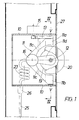
- a first embodiment is illustrated on the Figures 1 to 5.
- the device is mounted in a frame of support 10 and comprises a pivoting frame 11 mounted so as to be able to pivot around a pivot axis vertical V-V.
- the pivoting frame has two branches 11c which develop hoop-shaped between two heads 11a and 11b municipalities.
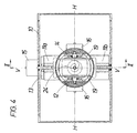
- the general shape of the frame 11 is clearly visible in Figure 3.
- These heads of the frame 11 are arranged to be able to pivot around a pivot axis vertical V-V.
- Each branch of the pivoting frame has a projecting arm 11d which serves as a support for an axis 12 defining a second pivot axis H-H, transverse at the first pivot axis V-V.
- Axis 12 is attached to each of the arms by a plain bearing or a ball bearing 14.
- a pin 12 is attached a shower head 20 which, in the embodiment illustrated as an example, consists of a hemispherical shell on the surface of which opens at 22 a water inlet pipe 24 (visible in Figure 2), connected to a water supply circuit 25 in which a solenoid valve 26 is inserted.
- the control of the pivoting movements of the frame 11 is made by electric motors, for example motors step by step or direct current.
- the frame 11 carries a sector 13 which is coupled to an electric motor 15.
- the rotation of the axis 12 around the pivot axis H-H is controlled by two electric motors 16 by means of toothed wheels 17-19.
- the swivel frame 11 oscillates horizontally, for example in a angle with an opening of about 45 °, while the axis 12 carrying the hemispherical shell 20 oscillates vertically, for example at an angle with a opening about 80 °.
- the hemispherical shell thus oscillates in space, directing the jet of water successively in different directions in space.
- the jet of water can thus sweep an area of action extending from the neck to the knees of a user and this on the entire width of the user's trunk. this allows the user's body to take full advantage of beneficial and / or therapeutic effects of the shower.
- the water pipe has or is connected to the at least one part 23 flexible or shaped so as to have sufficient flexibility.
- the reference sign 27 in the drawings designates a fixed front panel and the reference sign 28 designates a seal.
- the device is shown in Figure 5, mounted in a corner, it is obvious that it can be mounted on a flat wall. In addition, it is clear that the device can be mounted not only permanently but also so that it can slide along a structure rigid.
- pivoting frame 11 can be produced in an execution mode different from that illustrated by way of example in FIGS. 1 to 5.
- transverse pivot axes arranged on the swivel frame can be reversed to those determined by the illustrated arrangements in Figures 1 to 5.
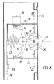
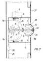
- FIGS 6 to 10 illustrate a second example of realization of the invention.
- This embodiment is similar to the one described above but uses a frame pivoting 11 in an alternative embodiment.
- heads 11a and 11b of frame 11, well visible in Figure 8 are curved and mounted to slide along two guide rails 13 in arc of a circle whose curvature is determined so their centers of curvature are located on a same vertical axis which defines the pivot axis V-V.
- the pivot axis H-H is realized, as in the example previously described, by a horizontal axis 12 which is carried by the two arms 11d projecting from the hoop branches 11c.
- H-H pivot axis crosses the pivot axis V-V so as to fix a point of central pivoting, fixed in space, around which oscillates the shower head shell 20.
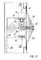
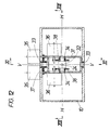
- Figures 11 to 13 illustrate a third example of embodiment of the invention.
- the device has two pivoting frames.
- a first frame 31 is mounted so that it can pivot around a first pivot axis V-V, defined by plain bearings or 33 ball bearings attached to a support frame 10.
- a second frame 32 is mounted so as to be able to pivot around a second axis pivoting H-H transverse to the first axis of pivoting and defined by plain bearings or ball bearings 34 attached to the frame 31.
- Each of the frames 31 and 32 is coupled to motors 35 and 36 by via toothed wheels 37 and 38.
- the shower head 42 is attached to the frame 32 and is connected to the water inlet duct 24.
- the apple shower 42 is connected to a cover plate 41 by a sealing bellows 43.
- the swivel frame 31 oscillates horizontally around the pivot axis V-V, for example in an angle with an opening by about 45 ° and the pivoting frame 32 bearing the shower head 42 swings vertically around the pivot axis H-H, for example at an angle having an opening of about 80 °.
- shower head is thus oriented in a variable manner in space, directing the water jet successively in different directions in space.
- the jet of water can thus sweep away an action zone which extends from the user's neck to the knees and this over the entire width of the trunk thereof, thereby providing the user all the beneficial and / or therapeutic effects from the shower.
- the transverse pivot axes arranged on the elements constituting the swivel frame can be reversed compared to those planned in the layout illustrated in figures 11 to 13.
- the invention allows to obtain an infinite variation of trajectories of the jet of water in the space during the shower, and at the discretion of the user himself so that he can enjoy fully, at its convenience, the effects of the shower on the body.
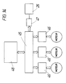
- FIG 14 is a general diagram the programmed control of the next shower unit the invention.
- the microprocessor 45 communicates with control devices 46 which drive the motors step by step controlling the pivoting movement horizontal swivel frame and swivel movement vertical of the shower head.
- the microprocessor also controls a relay 47 controlling a solenoid valve 26 inserted in the water supply circuit 25.
- the microprocessor 45 receives parameter adjustment commands oscillating movements of the water jet of a control panel 48 on which the oscillation adjustment values as well as types water jet trajectory defined or to be defined.
- the user chooses himself on the control panel 48 the desired mode of action among the options available and swing motion parameters of water jet in space.
- FIG. 15 illustrates by way of example an embodiment for controlling a device shower according to the invention when putting under device voltage.
- the device after centering the water jet the device is organized to allow to call three modes of action.
- the steps of the order are described below.
- Step 110 Choice of a memorized mode of action
- the paths of the water jet are made according to parameters previously stored by the user.
- Step 112 Designation of dynamic actions and / or static defined and memorized by the user.
- Step 114 Designated action.
- Step 120 Choice of a dynamic mode of action
- the water jet follows trajectories defined by the manufacturer on the basis of parameters that the user sets.
- Step 124 Choice of memorization or not of the trajectories designated and parameters defined in step 122.
- Step 126 Storage.
- Step 128 Designated action.
- Step 130 Choice of a static mode of action
- the water jet is frozen in space with an orientation and for a determined period of time chosen by the user.
- Step 132 Definition of the position of the water jet in the vertical plane and in the horizontal plane, and definition action time.
- Step 134 Choosing whether or not to store the position of the water jet and the action time defined at step 132.
- Step 136 Storage.
- Step 138 Designated action.
- Step 140 Control of the mechanical and hydraulic parts for the designated action.
- the chosen action cycle takes place under the programmed direction of the microprocessor.
- the example action command described above shows the wide range of movements of the water jet in space that allows the invention to be carried out at the choice of the user.
- This range of possibilities can include both previously defined trajectories programmed (e.g. random trajectories in uniform or variable sawtooth, in loops interrupted or not, spiral, etc.) that sequences of trajectories determined by the user himself.
- the effect of hydromassage can thus, thanks to the invention, be optimized at the option of each user.
- the programmed control of the trajectory of the water jet according to the invention can advantageously be completed a water flow adjustment depending on the direction jet and / or an adjustment of the water temperature of the jet.
Landscapes
- Health & Medical Sciences (AREA)
- Public Health (AREA)
- Life Sciences & Earth Sciences (AREA)
- Rehabilitation Therapy (AREA)
- Engineering & Computer Science (AREA)
- Pain & Pain Management (AREA)
- Animal Behavior & Ethology (AREA)
- General Health & Medical Sciences (AREA)
- Epidemiology (AREA)
- Veterinary Medicine (AREA)
- Physical Education & Sports Medicine (AREA)
- Hydrology & Water Resources (AREA)
- Water Supply & Treatment (AREA)
- Nozzles (AREA)
- Bathtubs, Showers, And Their Attachments (AREA)
- Massaging Devices (AREA)
- Percussion Or Vibration Massage (AREA)
- Catching Or Destruction (AREA)
Description
Dans ce mode d'action, les trajectoires du jet d'eau s'effectuent suivant des paramètres mémorisés antérieurement par l'utilisateur.
Dans ce mode d'action, le jet d'eau suit des trajectoires définies par le constructeur sur la base de paramètres que règle l'utilisateur.
- NC
- Nombre de cycles pour l'action à définir - comptage - après la définition des paramètres de chaque cycle.
- CN
- Numéro du cycle
- OA
- Origine action - Position par rapport à la position centrée de la partie mobile de l'appareil.
- TR
- Trajectoire du jet d'eau.
- SA
- Sens de l'action, du haut vers le vas ou inversément.
- RA
- Retour action, avec ou sans jet d'eau.
- VA
- Vitesse d'action.
- VR
- Vitesse de retour.
- AS
- Amplitude verticale supérieure.
- AI
- Amplitude verticale inférieure.
- AH
- Amplitude horizontale.
- TC
- Temps calculé pour un cycle.
- NP
- Nombre de passages avec la même trajectoire.
- TP
- Temps partiel pour la trajectoire.
- TT
- Temps total de l'action dynamique.
Dans ce mode d'action, le jet d'eau se trouve figé dans l'espace avec une orientation et pendant un laps de temps déterminé choisis par l'utilisateur.
Claims (14)
- Appareil de douche comprenant un corps pivotant portant une pomme de douche agencée pour produire au moins un jet d'eau, et comportant des moyens pour imprimer au corps un mouvement d'oscillation, le corps étant monté dans un bâti de support (10) et comprenant un premier élément (11, 31) agencé pour pivoter autour d'un premier axe de pivotement (par exemple V-V), caractérisé en ce que le corps pivotant comprend des moyens (14, 34) agencés sur l'élément pivotant précité pour définir un deuxième axe de pivotement (par exemple H-H) transversal au premier axe de pivotement, et un deuxième élément (12, 32) attaché aux moyens (14, 34) précités de manière à pouvoir pivoter autour du deuxième axe de pivotement (par exemple H-H), le deuxième élément pivotant précité portant la pomme de douche (20, 42), et en ce que l'appareil comporte des moyens pour imprimer au corps un mouvement d'oscillation autour de chaque axe de pivotement.
- Appareil suivant la revendication 1, caractérisé en ce que le premier élément pivotant comprend un cadre (11) comportant deux têtes (11a, 11b) montées pour pivoter autour d'un premier axe de pivotement (par exemple V-V) et un bras (11d) servant de support au deuxième élément pivotant (12) portant la pomme de douche.
- Appareil suivant la revendication 2, caractérisé en ce que les têtes (11a, 11b) du cadre pivotant (11) sont fixées à un moyen de pivotement (13) commandé par un moyen d'entraínement (15) pour imprimer au cadre (11) un mouvement de pivotement autour du premier axe de pivotement précité.
- Appareil suivant la revendication 2, caractérisé en ce que les têtes (11a, 11b) du cadre pivotant (11) sont agencées pour coulisser le long de guides (13) fixés à des moyens de support (10), les guides ayant une courbure dont le centre est de préférence situé sur le deuxième axe de rotation.
- Appareil suivant l'une quelconque des revendications précédentes, caractérisé en ce que la pomme de douche (20) est constituée d'une coquille à la surface de laquelle débouche le conduit d'arrivée d'eau.
- Appareil suivant la revendication 5, caractérisé en ce que la coquille (20) précitée a une forme pratiquement hémisphérique.
- Appareil suivant la revendication 1, caractérisé en ce que le premier élément pivotant comprend un premier cadre (31) agencé pour pivoter autour d'un premier axe de rotation (par exemple V-V),
des moyens (34) agencés sur le premier cadre pivotant pour définir un deuxième axe de rotation (par exemple H-H) transversal audit premier axe, et en ce que le deuxième élément pivotant comprend un deuxième cadre attaché de manière à pouvoir osciller autour du deuxième axe de rotation (H-H), ledit deuxième cadre portant la pomme de douche (42). - Appareil suivant la revendication 7, caractérisé en ce que la pomme de douche (42) est reliée à un élément fixe de l'appareil par l'intermédiaire d'un élément déformable (43).
- Appareil de douche suivant l'une quelconque des revendications précédentes, caractérisé en ce que les moyens pour imprimer les mouvements d'oscillations au cadre pivotant sont constitués par des moteurs pas-à-pas ou à courant continu.
- Appareil de douche suivant l'une quelconque des revendications précédentes, caractérisé en ce que les moyens pour imprimer les mouvements d'oscillations aux éléments pivotants sont commandés par un microprocesseur.
- Appareil de douche suivant la revendication 10, caractérisé en ce que le microprocesseur est dirigé par un programme pour régler la vitesse, l'amplitude et autres paramètres des mouvements d'oscillation des éléments pivotants du corps de l'appareil.
- Appareil suivant l'une quelconque des revendications 11 et 12, caractérisé en ce que le microprocesseur commande une électrovanne insérée dans le circuit d'alimentation en eau.
- Appareil de douche suivant l'une quelconque des revendications 10 à 12, caractérisé en ce qu'il comprend un tableau de commande pour modifier le programme de réglage et contrôler les paramètres des mouvements d'oscillation et/ou les types de trajectoire du jet d'eau dans l'espace.
- Appareil de jet d'eau comprenant un corps agencé pour lancer au moins un jet d'eau dans l'espace, caractérisé en ce que le corps est agencé comme décrit dans l'une quelconque des revendications précédentes.
Priority Applications (1)
| Application Number | Priority Date | Filing Date | Title |
|---|---|---|---|
| EP96934724A EP0898498B1 (fr) | 1996-05-13 | 1996-10-14 | Appareil a douche oscillante |
Applications Claiming Priority (4)
| Application Number | Priority Date | Filing Date | Title |
|---|---|---|---|
| WOPCT/EP96/02062 | 1996-05-13 | ||
| EP9602062 | 1996-05-13 | ||
| PCT/EP1996/004512 WO1997043047A1 (fr) | 1996-05-13 | 1996-10-14 | Appareil a douche oscillante |
| EP96934724A EP0898498B1 (fr) | 1996-05-13 | 1996-10-14 | Appareil a douche oscillante |
Publications (2)
| Publication Number | Publication Date |
|---|---|
| EP0898498A1 EP0898498A1 (fr) | 1999-03-03 |
| EP0898498B1 true EP0898498B1 (fr) | 2003-01-15 |
Family
ID=8166216
Family Applications (1)
| Application Number | Title | Priority Date | Filing Date |
|---|---|---|---|
| EP96934724A Expired - Lifetime EP0898498B1 (fr) | 1996-05-13 | 1996-10-14 | Appareil a douche oscillante |
Country Status (10)
| Country | Link |
|---|---|
| US (1) | US6148453A (fr) |
| EP (1) | EP0898498B1 (fr) |
| AT (1) | ATE231034T1 (fr) |
| AU (1) | AU7294596A (fr) |
| DE (1) | DE69625830T2 (fr) |
| DK (1) | DK0898498T3 (fr) |
| ES (1) | ES2191110T3 (fr) |
| NO (1) | NO985287L (fr) |
| PL (1) | PL181301B1 (fr) |
| WO (1) | WO1997043047A1 (fr) |
Families Citing this family (13)
| Publication number | Priority date | Publication date | Assignee | Title |
|---|---|---|---|---|
| US6908047B2 (en) | 2001-12-07 | 2005-06-21 | Nottingham Spirk, Llc | Oscillating shower sprayer |
| US7014128B2 (en) | 2002-10-01 | 2006-03-21 | Conair Corporation | Showerhead assembly |
| AU2003282855A1 (en) * | 2002-10-31 | 2004-06-07 | Conair Corporation | Hair treatment system and method |
| US7455247B2 (en) * | 2005-03-01 | 2008-11-25 | Kohler Co. | Bodyspray having adjustable spray orientation |
| EP1757260A1 (fr) | 2005-08-23 | 2007-02-28 | Giovanni Luigi Sartor | Procédé et logiciel de pilotage et de gestion d'un appareil d'hydromassage par douche au jet, en ce compris la définition et l'execution des actions et traitements |
| US20100059604A1 (en) * | 2006-03-02 | 2010-03-11 | Toto Ltd. | Shower apparatus |
| EP1997408B1 (fr) * | 2006-03-02 | 2011-12-28 | Toto Ltd. | Dispositif de douche et cabine de douche |
| WO2007102193A1 (fr) * | 2006-03-06 | 2007-09-13 | Toto Ltd. | Dispositif d'évacuation d'eau |
| DE102007003416A1 (de) * | 2007-01-16 | 2008-07-17 | Hansgrohe Ag | Duschvorrichtung |
| US8157192B2 (en) | 2008-05-20 | 2012-04-17 | James Claas | Fluid activated nozzle |
| US8978175B2 (en) * | 2010-03-16 | 2015-03-17 | Edgar L. Bronstein | Variable position shower apparatus and related methods |
| US20150034732A1 (en) * | 2013-08-01 | 2015-02-05 | Droplet Robotics Inc. | Articulated watering device |
| US9868125B2 (en) | 2015-01-19 | 2018-01-16 | Moen Incorporated | Multifunction pivoting body spray |
Family Cites Families (7)
| Publication number | Priority date | Publication date | Assignee | Title |
|---|---|---|---|---|
| GB1605006A (en) * | 1961-07-05 | 1981-12-16 | British Aircraft Corp Ltd | Rocket motors |
| CH566173A5 (fr) * | 1973-06-04 | 1975-09-15 | Aeromatic Ag | |
| JPH0753027Y2 (ja) * | 1990-10-02 | 1995-12-06 | 日本トムソン株式会社 | 遠隔操作形自在旋回ノズル |
| FR2675376A1 (fr) * | 1991-04-17 | 1992-10-23 | Antoine Robert | Dispositif de massage hydrodynamique. |
| FR2681244B3 (fr) * | 1991-09-18 | 1994-11-25 | Gianfranco Zino | Appareillage pour l'hydromassage vertical a fonctionnement automatique et controle electronique. |
| US5321860A (en) * | 1991-11-08 | 1994-06-21 | Kohler Co. | Shower enclosure assembly |
| IL108866A0 (en) * | 1994-03-06 | 1994-06-24 | Golan Zeev | A method and devices for shower |
-
1996
- 1996-10-14 PL PL96329852A patent/PL181301B1/pl not_active IP Right Cessation
- 1996-10-14 EP EP96934724A patent/EP0898498B1/fr not_active Expired - Lifetime
- 1996-10-14 US US09/180,713 patent/US6148453A/en not_active Expired - Lifetime
- 1996-10-14 AT AT96934724T patent/ATE231034T1/de not_active IP Right Cessation
- 1996-10-14 DK DK96934724T patent/DK0898498T3/da active
- 1996-10-14 WO PCT/EP1996/004512 patent/WO1997043047A1/fr not_active Ceased
- 1996-10-14 ES ES96934724T patent/ES2191110T3/es not_active Expired - Lifetime
- 1996-10-14 DE DE69625830T patent/DE69625830T2/de not_active Expired - Fee Related
- 1996-10-14 AU AU72945/96A patent/AU7294596A/en not_active Abandoned
-
1998
- 1998-11-13 NO NO985287A patent/NO985287L/no not_active Application Discontinuation
Also Published As
| Publication number | Publication date |
|---|---|
| PL329852A1 (en) | 1999-04-12 |
| WO1997043047A1 (fr) | 1997-11-20 |
| AU7294596A (en) | 1997-12-05 |
| ATE231034T1 (de) | 2003-02-15 |
| DE69625830T2 (de) | 2003-08-14 |
| NO985287D0 (no) | 1998-11-13 |
| DE69625830D1 (de) | 2003-02-20 |
| PL181301B1 (pl) | 2001-07-31 |
| NO985287L (no) | 1999-01-13 |
| DK0898498T3 (da) | 2003-05-05 |
| US6148453A (en) | 2000-11-21 |
| EP0898498A1 (fr) | 1999-03-03 |
| ES2191110T3 (es) | 2003-09-01 |
Similar Documents
| Publication | Publication Date | Title |
|---|---|---|
| EP0676241A2 (fr) | Pomme de douche à mouvement périodique | |
| WO1997043047A1 (fr) | Appareil a douche oscillante | |
| CA2739233C (fr) | Dispositif de mobilisation corporelle et utilisation d'un tel dispositif | |
| FR2637791A1 (fr) | Appareil de bercement pour siege d'enfant | |
| EP0600892B1 (fr) | Dispositif de massage hydrodynamique | |
| FR2659550A1 (fr) | Appareil de massage. | |
| FR2789304A1 (fr) | Attelle de mobilisation passive du membre superieur | |
| US1984397A (en) | Mechanical chair | |
| US7216935B2 (en) | Dynamic chair | |
| FR2860713A1 (fr) | Attelle de mobilisation passive de l'articulation de la cheville | |
| US20020042242A1 (en) | Motion toy | |
| FR2715837A1 (fr) | Appareil de massage du type d'un coussin ou d'un élément analogue à générateurs électriques de vibrations. | |
| CN213962565U (zh) | 按摩椅的可调节转动头罩 | |
| JP2000308663A (ja) | マッサージ椅子 | |
| JPH05329226A (ja) | 揺動及び回転可能な椅子 | |
| LU87587A1 (fr) | Objet decoratif mobile | |
| JP3641029B2 (ja) | 可動人形体 | |
| KR19990006078U (ko) | 허리운동의자 | |
| JP3508771B2 (ja) | マッサージ椅子 | |
| JP2009045078A (ja) | 装具および健康器具セット | |
| JP2020141979A (ja) | 座椅子型マッサージ機 | |
| KR0131987Y1 (ko) | 안락 의자 | |
| JP2005237485A (ja) | マッサージ椅子 | |
| FR2478474A1 (fr) | Appareil permettant de faire des mouvements de culture physique | |
| CH621701A5 (en) | Apparatus allowing stimulation and promotion of the blood flow |
Legal Events
| Date | Code | Title | Description |
|---|---|---|---|
| PUAI | Public reference made under article 153(3) epc to a published international application that has entered the european phase |
Free format text: ORIGINAL CODE: 0009012 |
|
| 17P | Request for examination filed |
Effective date: 19981204 |
|
| AK | Designated contracting states |
Kind code of ref document: A1 Designated state(s): AT BE CH DE DK ES FI FR GB GR IE IT LI LU MC NL PT SE |
|
| GRAG | Despatch of communication of intention to grant |
Free format text: ORIGINAL CODE: EPIDOS AGRA |
|
| 17Q | First examination report despatched |
Effective date: 20010928 |
|
| GRAG | Despatch of communication of intention to grant |
Free format text: ORIGINAL CODE: EPIDOS AGRA |
|
| GRAH | Despatch of communication of intention to grant a patent |
Free format text: ORIGINAL CODE: EPIDOS IGRA |
|
| GRAH | Despatch of communication of intention to grant a patent |
Free format text: ORIGINAL CODE: EPIDOS IGRA |
|
| GRAA | (expected) grant |
Free format text: ORIGINAL CODE: 0009210 |
|
| RIC1 | Information provided on ipc code assigned before grant |
Free format text: 7B 05B 3/16 A, 7E 03C 1/06 B, 7A 47K 3/28 B |
|
| AK | Designated contracting states |
Kind code of ref document: B1 Designated state(s): AT BE CH DE DK ES FI FR GB GR IE IT LI LU MC NL PT SE |
|
| REG | Reference to a national code |
Ref country code: GB Ref legal event code: FG4D Free format text: NOT ENGLISH Ref country code: CH Ref legal event code: EP |
|
| REG | Reference to a national code |
Ref country code: IE Ref legal event code: FG4D Free format text: FRENCH |
|
| REF | Corresponds to: |
Ref document number: 69625830 Country of ref document: DE Date of ref document: 20030220 Kind code of ref document: P |
|
| REG | Reference to a national code |
Ref country code: SE Ref legal event code: TRGR |
|
| REG | Reference to a national code |
Ref country code: CH Ref legal event code: NV Representative=s name: R. A. EGLI & CO. PATENTANWAELTE |
|
| REG | Reference to a national code |
Ref country code: DK Ref legal event code: T3 |
|
| REG | Reference to a national code |
Ref country code: GR Ref legal event code: EP Ref document number: 20030401281 Country of ref document: GR |
|
| GBT | Gb: translation of ep patent filed (gb section 77(6)(a)/1977) |
Effective date: 20030516 |
|
| REG | Reference to a national code |
Ref country code: ES Ref legal event code: FG2A Ref document number: 2191110 Country of ref document: ES Kind code of ref document: T3 |
|
| PLBE | No opposition filed within time limit |
Free format text: ORIGINAL CODE: 0009261 |
|
| STAA | Information on the status of an ep patent application or granted ep patent |
Free format text: STATUS: NO OPPOSITION FILED WITHIN TIME LIMIT |
|
| 26N | No opposition filed |
Effective date: 20031016 |
|
| PGFP | Annual fee paid to national office [announced via postgrant information from national office to epo] |
Ref country code: MC Payment date: 20060922 Year of fee payment: 11 Ref country code: FI Payment date: 20060922 Year of fee payment: 11 |
|
| PGFP | Annual fee paid to national office [announced via postgrant information from national office to epo] |
Ref country code: GB Payment date: 20060926 Year of fee payment: 11 Ref country code: CH Payment date: 20060926 Year of fee payment: 11 Ref country code: AT Payment date: 20060926 Year of fee payment: 11 |
|
| PGFP | Annual fee paid to national office [announced via postgrant information from national office to epo] |
Ref country code: NL Payment date: 20060927 Year of fee payment: 11 Ref country code: LU Payment date: 20060927 Year of fee payment: 11 Ref country code: DK Payment date: 20060927 Year of fee payment: 11 |
|
| PGFP | Annual fee paid to national office [announced via postgrant information from national office to epo] |
Ref country code: IE Payment date: 20060928 Year of fee payment: 11 Ref country code: GR Payment date: 20060928 Year of fee payment: 11 Ref country code: DE Payment date: 20060928 Year of fee payment: 11 |
|
| PGFP | Annual fee paid to national office [announced via postgrant information from national office to epo] |
Ref country code: SE Payment date: 20060929 Year of fee payment: 11 |
|
| PGFP | Annual fee paid to national office [announced via postgrant information from national office to epo] |
Ref country code: PT Payment date: 20061003 Year of fee payment: 11 |
|
| PGFP | Annual fee paid to national office [announced via postgrant information from national office to epo] |
Ref country code: IT Payment date: 20061031 Year of fee payment: 11 |
|
| REG | Reference to a national code |
Ref country code: PT Ref legal event code: MM4A Free format text: LAPSE DUE TO NON-PAYMENT OF FEES Effective date: 20080414 |
|
| BERE | Be: lapsed |
Owner name: *SARTOR GIOVANNI LUIGI Effective date: 20071031 |
|
| PG25 | Lapsed in a contracting state [announced via postgrant information from national office to epo] |
Ref country code: MC Free format text: LAPSE BECAUSE OF NON-PAYMENT OF DUE FEES Effective date: 20071031 |
|
| REG | Reference to a national code |
Ref country code: DK Ref legal event code: EBP |
|
| EUG | Se: european patent has lapsed | ||
| GBPC | Gb: european patent ceased through non-payment of renewal fee |
Effective date: 20071014 |
|
| REG | Reference to a national code |
Ref country code: CH Ref legal event code: PL |
|
| NLV4 | Nl: lapsed or anulled due to non-payment of the annual fee |
Effective date: 20080501 |
|
| PG25 | Lapsed in a contracting state [announced via postgrant information from national office to epo] |
Ref country code: LI Free format text: LAPSE BECAUSE OF NON-PAYMENT OF DUE FEES Effective date: 20071031 Ref country code: FI Free format text: LAPSE BECAUSE OF NON-PAYMENT OF DUE FEES Effective date: 20071014 Ref country code: DE Free format text: LAPSE BECAUSE OF NON-PAYMENT OF DUE FEES Effective date: 20080501 Ref country code: CH Free format text: LAPSE BECAUSE OF NON-PAYMENT OF DUE FEES Effective date: 20071031 |
|
| PG25 | Lapsed in a contracting state [announced via postgrant information from national office to epo] |
Ref country code: AT Free format text: LAPSE BECAUSE OF NON-PAYMENT OF DUE FEES Effective date: 20071014 |
|
| BERR | Be: reestablished |
Owner name: *SARTOR GIOVANNI LUIGI Effective date: 20080805 |
|
| PG25 | Lapsed in a contracting state [announced via postgrant information from national office to epo] |
Ref country code: PT Free format text: LAPSE BECAUSE OF NON-PAYMENT OF DUE FEES Effective date: 20080414 Ref country code: BE Free format text: LAPSE BECAUSE OF NON-PAYMENT OF DUE FEES Effective date: 20071031 |
|
| REG | Reference to a national code |
Ref country code: FR Ref legal event code: ST Effective date: 20080630 |
|
| PG25 | Lapsed in a contracting state [announced via postgrant information from national office to epo] |
Ref country code: SE Free format text: LAPSE BECAUSE OF NON-PAYMENT OF DUE FEES Effective date: 20071015 Ref country code: NL Free format text: LAPSE BECAUSE OF NON-PAYMENT OF DUE FEES Effective date: 20080501 Ref country code: IE Free format text: LAPSE BECAUSE OF NON-PAYMENT OF DUE FEES Effective date: 20071015 Ref country code: DK Free format text: LAPSE BECAUSE OF NON-PAYMENT OF DUE FEES Effective date: 20071031 |
|
| REG | Reference to a national code |
Ref country code: FR Ref legal event code: RN |
|
| PG25 | Lapsed in a contracting state [announced via postgrant information from national office to epo] |
Ref country code: GB Free format text: LAPSE BECAUSE OF NON-PAYMENT OF DUE FEES Effective date: 20071014 |
|
| REG | Reference to a national code |
Ref country code: FR Ref legal event code: FC |
|
| PGRI | Patent reinstated in contracting state [announced from national office to epo] |
Ref country code: BE Effective date: 20080805 |
|
| PGRI | Patent reinstated in contracting state [announced from national office to epo] |
Ref country code: FR Effective date: 20081113 |
|
| PG25 | Lapsed in a contracting state [announced via postgrant information from national office to epo] |
Ref country code: GR Free format text: LAPSE BECAUSE OF NON-PAYMENT OF DUE FEES Effective date: 20080505 |
|
| PG25 | Lapsed in a contracting state [announced via postgrant information from national office to epo] |
Ref country code: LU Free format text: LAPSE BECAUSE OF NON-PAYMENT OF DUE FEES Effective date: 20071014 Ref country code: IT Free format text: LAPSE BECAUSE OF NON-PAYMENT OF DUE FEES Effective date: 20071014 |
|
| PGFP | Annual fee paid to national office [announced via postgrant information from national office to epo] |
Ref country code: ES Payment date: 20141006 Year of fee payment: 19 Ref country code: FR Payment date: 20141021 Year of fee payment: 19 |
|
| PGFP | Annual fee paid to national office [announced via postgrant information from national office to epo] |
Ref country code: BE Payment date: 20141022 Year of fee payment: 19 |
|
| REG | Reference to a national code |
Ref country code: FR Ref legal event code: ST Effective date: 20160630 |
|
| PG25 | Lapsed in a contracting state [announced via postgrant information from national office to epo] |
Ref country code: FR Free format text: LAPSE BECAUSE OF NON-PAYMENT OF DUE FEES Effective date: 20151102 |
|
| REG | Reference to a national code |
Ref country code: ES Ref legal event code: FD2A Effective date: 20161128 |
|
| PG25 | Lapsed in a contracting state [announced via postgrant information from national office to epo] |
Ref country code: ES Free format text: LAPSE BECAUSE OF NON-PAYMENT OF DUE FEES Effective date: 20151015 |
|
| PG25 | Lapsed in a contracting state [announced via postgrant information from national office to epo] |
Ref country code: BE Free format text: LAPSE BECAUSE OF NON-PAYMENT OF DUE FEES Effective date: 20151031 |