EP0898930A2 - Procédé et dispositif pour l'examen de la vision binoculaire - Google Patents
Procédé et dispositif pour l'examen de la vision binoculaire Download PDFInfo
- Publication number
- EP0898930A2 EP0898930A2 EP98116131A EP98116131A EP0898930A2 EP 0898930 A2 EP0898930 A2 EP 0898930A2 EP 98116131 A EP98116131 A EP 98116131A EP 98116131 A EP98116131 A EP 98116131A EP 0898930 A2 EP0898930 A2 EP 0898930A2
- Authority
- EP
- European Patent Office
- Prior art keywords
- head
- view
- field
- examination
- screen
- Prior art date
- Legal status (The legal status is an assumption and is not a legal conclusion. Google has not performed a legal analysis and makes no representation as to the accuracy of the status listed.)
- Granted
Links
- 230000004438 eyesight Effects 0.000 title claims abstract description 18
- 238000000034 method Methods 0.000 title claims description 24
- 238000012360 testing method Methods 0.000 claims abstract description 16
- 210000003128 head Anatomy 0.000 claims description 61
- 238000001514 detection method Methods 0.000 claims description 13
- 208000004350 Strabismus Diseases 0.000 claims description 8
- 238000005259 measurement Methods 0.000 claims description 7
- 239000011521 glass Substances 0.000 claims description 6
- 208000019430 Motor disease Diseases 0.000 claims description 3
- 238000002604 ultrasonography Methods 0.000 claims description 3
- 208000020764 Sensation disease Diseases 0.000 claims description 2
- 230000006870 function Effects 0.000 claims description 2
- 230000004886 head movement Effects 0.000 abstract description 3
- 238000011156 evaluation Methods 0.000 abstract 1
- 230000000007 visual effect Effects 0.000 description 7
- 238000011835 investigation Methods 0.000 description 6
- 230000004308 accommodation Effects 0.000 description 5
- 230000004220 muscle function Effects 0.000 description 4
- 230000036544 posture Effects 0.000 description 4
- 230000037152 sensory function Effects 0.000 description 4
- 230000000295 complement effect Effects 0.000 description 3
- 230000004927 fusion Effects 0.000 description 3
- 238000000926 separation method Methods 0.000 description 3
- 208000016285 Movement disease Diseases 0.000 description 2
- 238000003745 diagnosis Methods 0.000 description 2
- 208000037265 diseases, disorders, signs and symptoms Diseases 0.000 description 2
- 230000000694 effects Effects 0.000 description 2
- 230000007659 motor function Effects 0.000 description 2
- 210000003205 muscle Anatomy 0.000 description 2
- 230000005693 optoelectronics Effects 0.000 description 2
- 208000029578 Muscle disease Diseases 0.000 description 1
- 208000021642 Muscular disease Diseases 0.000 description 1
- 206010033799 Paralysis Diseases 0.000 description 1
- 230000007547 defect Effects 0.000 description 1
- 230000001419 dependent effect Effects 0.000 description 1
- 238000013461 design Methods 0.000 description 1
- 238000010586 diagram Methods 0.000 description 1
- 230000001815 facial effect Effects 0.000 description 1
- 238000007689 inspection Methods 0.000 description 1
- 239000003550 marker Substances 0.000 description 1
- 210000005036 nerve Anatomy 0.000 description 1
- 210000001525 retina Anatomy 0.000 description 1
- 230000001953 sensory effect Effects 0.000 description 1
- 230000004304 visual acuity Effects 0.000 description 1
Images

Classifications
-
- A—HUMAN NECESSITIES
- A61—MEDICAL OR VETERINARY SCIENCE; HYGIENE
- A61B—DIAGNOSIS; SURGERY; IDENTIFICATION
- A61B3/00—Apparatus for testing the eyes; Instruments for examining the eyes
- A61B3/02—Subjective types, i.e. testing apparatus requiring the active assistance of the patient
- A61B3/028—Subjective types, i.e. testing apparatus requiring the active assistance of the patient for testing visual acuity; for determination of refraction, e.g. phoropters
- A61B3/032—Devices for presenting test symbols or characters, e.g. test chart projectors
-
- A—HUMAN NECESSITIES
- A61—MEDICAL OR VETERINARY SCIENCE; HYGIENE
- A61B—DIAGNOSIS; SURGERY; IDENTIFICATION
- A61B3/00—Apparatus for testing the eyes; Instruments for examining the eyes
- A61B3/02—Subjective types, i.e. testing apparatus requiring the active assistance of the patient
- A61B3/08—Subjective types, i.e. testing apparatus requiring the active assistance of the patient for testing binocular or stereoscopic vision, e.g. strabismus
Definitions
- the invention relates to a method and an arrangement for examination of double-eyed (binocular) vision.
- Tests in as many directions as possible are required. Mathematically seen an infinite number of viewing directions are possible. Physiologically sensible and the examination in the nine main gaze directions is suitable for basic diagnostics. These are: top left, top, top right, left, straight, right, bottom left, bottom, bottom right.
- the determined deviations of the The directions of vision of both eyes can be specified in degrees or in Prism diopter.
- the eye muscle functions can also be checked by means of so-called coordinimetry.
- coordinimetry Here are squint angles illustrated by the deviations in the gaze directions of both eyes graphically represented from the main viewing directions in a diagram become. Testing is carried out using so-called "tangent tables".
- the image separation can be on different kind. The most common is the image separation by complementary colored fixation objects and complementary colored filter glasses.
- the examiner points a red light mark at you Fixation point.
- the subject who wears red-green glasses sees the red one Light mark only with the eye in front of which the red glass is located. He should green light mark, which he only sees with the other eye, with the red one Bring the light mark to cover.
- the location of the green marker on the Umbrella relative to the fixed red dots gives the relative position of the Eye axes to each other. It is at least in the 9 main lines of sight checked, entered in a scheme and for diagnosis evaluated.
- Viewing angles are determined by the head position and the location of the Facial line.
- the face line is the straight line through the fixation point and the Center of the retina (foveola).
- the patient's eyes are always in relation to his or her eyes Head posture. So far there are only two basic ones Measurement options: In the first, the patient's head is placed in a Basic position fixed, and then the patient has to change his viewing directions. With the second option, the patient must always be in the middle, for example look at a projection screen, the desired viewing angle, such as for example 30 ° upwards, by the opposite movement of the head the patient should be set 30 ° downwards.
- a Hess, Lee or Helmholtz coordinate meter is used Use, in the second example the tangent scale according to Harms.
- the head is fixed and the viewing directions are variable, or that The viewing direction is fixed and the head is moved.
- Coordinimeters in use are already at an examination distance of 50 cm relatively large and heavy.
- the Helmholtz umbrella for example, has a width and height of 1.30 m. You would be the umbrella smaller, the patient would have to move closer to the screen. At Objects that are nearby must be accommodated and the Eyes have to move in opposite directions, i.e. they have to converge. Thus the influences of convergence and accommodation can be disruptive affect the result of the investigation. It would be ideal if you had one located in the infinite tangent table or one in the Can check infinite coordimeter located. Then there would be none Accommodation is required and the visual axes of both eyes are parallel to each other.
- the short inspection distance is a major disadvantage when coordinating on the Hess or Helmholtz umbrella. If you enlarge the Examination distance, then the required area for the examination device too large. With an examination distance of for example, 2.5 m would hardly be accommodation and convergence still annoying, but the screen should already have a width and a height of more than 5 m, if possible, have a squint angle to display or measure graphically when looking up to 45 °. Accordingly, the space required for accommodation or Convergence little disrupted investigation with previous methods disadvantageous.
- DE 40 41 332 C2 shows an example of projection coordination.
- the same principle is shown in US 5,302,981, but the Projection screen along an extension direction to a bar is shrunk, which is positioned either horizontally or vertically.
- WO 96 13 195 A1 relates to examinations of double-eyed vision under Use of the Harms method or the Hess / Helmholtz method.
- US 2,724,305 shows how the head posture can be optically controlled a mirror attached to the subject's head. From the Head position should then be inferred from the line of sight.
- the invention has for its object a method for investigation to create motor and sensory functions of the eyes, in which the Examination distance is variable and at the same time on a fixation of the head can be dispensed with.
- the two-eyed field of vision has one in the horizontal Extension of 100 °, in the vertical extension of about 90 °. Now but the squint angles to be measured are usually much smaller, so that in usually only a sub-area of the entire field of view for the measurement is relevant. For example, if you want an eye muscle function in the Measure line of sight down 20 °, then the upper area of the Field of view on the screen not used. The for the respective examination section irrelevant areas of the screen, tangent table, the area or space on which the field of vision is or in which projected the field of view can also be disregarded.
- respective position data for a head position of a subject in the room With the help of this position data and with With the help of the field of view coordinates stored in advance in the computer, the respective test area of the field of view according to the head position in Real time shifted.
- Programs stored in the computer can be used in the different visual objects for each Representation. For testing the motor skills, for example the fixation points of the tangent tables or the coordinate meters Show. Any other visual objects can be displayed Testing sensory functions such as determining the Fusion field of view or the determination of the fusion width in different Viewing directions, for the detection of prismatic side effects of Eyeglass lenses and for checking visual acuity depending on Point of view of the lens.
- the Viewing angle can always be kept constant.
- the whole Field of view examined or measured.
- the previous ones Methods caused by incorrect head position or by changing the head position Possible measurement errors during the examination are excluded.
- the cut-out representation of the field of view Space requirement reduced and / or the examination distance increased.
- the "straight ahead" corresponds to the direction of view Fixation mark shown in the middle of the projection surface. Does he keep his For example, head turned 15 ° to the right, then appears in the middle the fixation mark on the projection surface, with the head held straight a look of 15 ° to the left could be fixed. If the moves Head wanted or unwanted during an examination, then move the fixation marks within the boundaries of the projection surfaces. As a result, the viewing angle remains constant even though the viewing direction changes.
- the representation of the points to be fixed and marked and that too their reference coordinate system, the can optionally be shown in detail takes place dynamically, that means through continuous recalculation in real time on the basis of Starting coordinates.
- the two principles of squint angle determination given at the beginning are combined according to the invention so that it is a constant, fixed Head position and a fixed direction of view of the fixing eye is not there are two variables instead, the variability of The viewing direction depends on the size of the screen or the projection device.
- the field of view to be checked is no longer device or limited by the device because the head is free in all directions is mobile.
- the space required for the examination device can be decrease significantly and there will be a larger examination distance enables.
- the invention has the particular advantage that sensory Tests, for example in the case of glasses intolerance, and motor tests Disorders, such as paralysis of an eye muscle, automatically and have it self-registered.
- a subject, for image separation wearing red-green glasses as described above can be done by moving the head of the field of view so long in vertical or horizontal Shift direction until a fixation object is below a certain one Perspective appears.
- the fixation object can be a red or green ring, in which a complementary colored cross is to be centered.
- the subject steers the cross with a marking device, one "Joystick” or a “mouse", and confirms the overlay of both Markings at the push of a button.
- the number of "balloons to be shot” gives from the number of gaze directions to be checked.
- the detection of the head position can best be done on optoelectronic Ways. To do this, the light reflections from on the subject's head attached reflectors detected by at least one video camera and in Computer evaluated. Light sources, preferably lasers, can also be fix it on the subject's head. Three light sources are preferred used. These three light sources each direct diverging light beams onto a surface that is in turn scanned by a video camera. The Light rays mark the corner points of a pyramid base on the surface. From the position of the light points - with known and constant Distance between light sources and eyes the position of the eyes calculate in space. If the height of the head changes during the Examination does not change, could be limited to two light sources be made. Instead of optoelectronic detection of the In principle, all other systems for recording the Spatial coordinates of an object conceivable, such as tilt sensor systems or ultrasound systems.
- the method according to the invention and the associated arrangement are more flexible than conventional investigations of the with two eyes.
- the examination distance can be changed freely. It is no longer necessary to fix a subject's head.
- the Examination can run automatically under program control, which saves time and personnel can be saved.
- the position data of the head is recorded numerically in real time. you decide taking into account the examination distance for each Examination section required field of view.
- the determined Deviations are measured by continuous recalculation in Dependence on the head position based on the digitally stored Initial coordinates of the overall field of vision.
- 1 shows an arrangement for carrying out the method for examination of double-eyed vision according to the invention.
- 1 shows a chair 1 for a patient with a detection device 2 for Determine his head position, a computer 3 with a memory for Save the coordinate systems and a selector, one Display device 4 and a marking device 5, such as a so-called joystick or a so-called mouse, with which the Patient can mark an examination site and make a presentation the display device 4 with a section of a coordinate system.
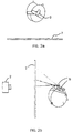
- 2 shows the head of a patient to which directional emitters 9 are fixed, in relation to the impact surface 7.
- the 2a and 2b are directional emitters 9 on the patient's head so fixed that it has a definite and firm relation to his eyes To have position. During the examination, give them on the patient's head fixed directional spotlight 9 light from the impact surface 7.
- the target 7 is by means of the detection device 2 to determine the head position of the Patients or subjects observed.
- the detection device 2 is in the Case in which the directional emitters 9 are light emitters, for example one Video camera.
- the directional emitters 9 can also be ultrasound emitters.
- An examination area can be set before the examination.
- the patient When the selected section of the coordinate system is displayed, the patient must use the marking device 5 to mark the examination site actuate.
- the measurement result is in the form of electrical Signals led to the computer 3, in which they are binary coded. Then based on the coded signals, a section of the desired Field of view selected, its coordinates in the computer's memory digital are saved. Along with the field of view coordinates are in the computer also the positions of the fixation objects, the test marks and the optotypes saved.
- the selection can be made using a table, for example take place, which is an assignment between recorded position data of the header and the digitally stored values for the position of the visual objects within of the field of view coordinate system. The subject observed the on the Display device 4 objects shown.
- the display device 4 On the display device 4 are the spherical coordinates of the field of view projected onto the display surface shown.
- a marking device 5 such as one So-called mouse or a so-called joystick
- the subject moves the cross, which he can only see with one eye, so that it is with the Circle, which he can only see with the other eye, overlays. This He marks the position, for example, by pressing a button on the Marking device 5. Because the images of both eyes are fused If there is a fault, deviations become apparent that differ from the Computer 3 can be saved and evaluated. Moves the Test subject's head, then those on the projection device also move shown fixation points because each head position a certain Section of the field of view is assigned.
- FIG. 2a A lateral movement of the head is shown in Fig. 2a, and one Movement of the head up or down is shown in Fig. 2b.
- Fig. 2b In 2a and 2b is the beam path of the emitted by the source 9 Rays can be seen for two positions of the head. These rays are then detected by means of the detection device 2.
Landscapes
- Life Sciences & Earth Sciences (AREA)
- Health & Medical Sciences (AREA)
- Medical Informatics (AREA)
- Biophysics (AREA)
- Ophthalmology & Optometry (AREA)
- Engineering & Computer Science (AREA)
- Biomedical Technology (AREA)
- Heart & Thoracic Surgery (AREA)
- Physics & Mathematics (AREA)
- Molecular Biology (AREA)
- Surgery (AREA)
- Animal Behavior & Ethology (AREA)
- General Health & Medical Sciences (AREA)
- Public Health (AREA)
- Veterinary Medicine (AREA)
- Eye Examination Apparatus (AREA)
- Length Measuring Devices By Optical Means (AREA)
Applications Claiming Priority (2)
| Application Number | Priority Date | Filing Date | Title |
|---|---|---|---|
| DE19737119A DE19737119C1 (de) | 1997-08-26 | 1997-08-26 | Verfahren und Anordnung zur Untersuchung des beidäugigen Sehens |
| DE19737119 | 1997-08-26 |
Publications (3)
| Publication Number | Publication Date |
|---|---|
| EP0898930A2 true EP0898930A2 (fr) | 1999-03-03 |
| EP0898930A3 EP0898930A3 (fr) | 2000-03-22 |
| EP0898930B1 EP0898930B1 (fr) | 2002-07-31 |
Family
ID=7840203
Family Applications (1)
| Application Number | Title | Priority Date | Filing Date |
|---|---|---|---|
| EP98116131A Expired - Lifetime EP0898930B1 (fr) | 1997-08-26 | 1998-08-26 | Procédé et dispositif pour l'examen de la vision binoculaire |
Country Status (2)
| Country | Link |
|---|---|
| EP (1) | EP0898930B1 (fr) |
| DE (2) | DE19737119C1 (fr) |
Cited By (3)
| Publication number | Priority date | Publication date | Assignee | Title |
|---|---|---|---|---|
| EP1862110A1 (fr) * | 2006-05-29 | 2007-12-05 | Essilor International (Compagnie Generale D'optique) | Procédé d'optimisation de verres de lunettes |
| WO2010145736A1 (fr) * | 2009-06-17 | 2010-12-23 | Carl Zeiss Vision Gmbh | Procédé et dispositif de détermination du port de tête habituel |
| EP2366328A1 (fr) | 2010-03-16 | 2011-09-21 | Ignaz Alois Stuetz | Mesure différentielle de la position monoculaire à binoculaire des yeux |
Families Citing this family (1)
| Publication number | Priority date | Publication date | Assignee | Title |
|---|---|---|---|---|
| CN105832284B (zh) * | 2016-03-18 | 2017-04-26 | 周凌云 | 一种双眼视像分离检测装置及方法 |
Citations (7)
| Publication number | Priority date | Publication date | Assignee | Title |
|---|---|---|---|---|
| US2724305A (en) | 1951-09-04 | 1955-11-22 | Herman F Brandt | Apparatus for recording eye movement |
| US5302981A (en) | 1992-10-22 | 1994-04-12 | Wirtz Paul C | Method and apparatus to correct vertical and lateral double vision |
| DE4041332C2 (de) | 1990-12-21 | 1994-05-19 | Bernhard Dr Loew | Vorrichtung zum Überwachen der Kopfhaltung eines Patienten während der Schieluntersuchung mittels eines Projektions-Koordimeters |
| JPH0838426A (ja) | 1994-07-27 | 1996-02-13 | Canon Inc | 検眼装置 |
| WO1996013195A1 (fr) | 1994-10-29 | 1996-05-09 | Interstaatliche Ingenieurschule Neu-Technikum Buchs | Procede et dispositif de determination de deviations horizontales, verticales et/ou cycliques de l'oeil |
| DE19502337A1 (de) | 1993-08-10 | 1996-08-08 | Johannes Braeuning | Vorrichtung und Verfahren zur Prüfung von Sehfunktionen |
| DE19505399A1 (de) | 1995-02-17 | 1996-08-22 | Oculus Optikgeraete Gmbh | Verfahren und Aufbau zur Untersuchung des Gesichtsfeldes unter Zuhilfenahme von Augenbewegungen |
Family Cites Families (1)
| Publication number | Priority date | Publication date | Assignee | Title |
|---|---|---|---|---|
| GB2115179B (en) * | 1978-12-21 | 1984-01-18 | Redifon Simulation Ltd | Improvements in or relating to visual display apparatus |
-
1997
- 1997-08-26 DE DE19737119A patent/DE19737119C1/de not_active Expired - Fee Related
-
1998
- 1998-08-26 DE DE59804975T patent/DE59804975D1/de not_active Expired - Fee Related
- 1998-08-26 EP EP98116131A patent/EP0898930B1/fr not_active Expired - Lifetime
Patent Citations (7)
| Publication number | Priority date | Publication date | Assignee | Title |
|---|---|---|---|---|
| US2724305A (en) | 1951-09-04 | 1955-11-22 | Herman F Brandt | Apparatus for recording eye movement |
| DE4041332C2 (de) | 1990-12-21 | 1994-05-19 | Bernhard Dr Loew | Vorrichtung zum Überwachen der Kopfhaltung eines Patienten während der Schieluntersuchung mittels eines Projektions-Koordimeters |
| US5302981A (en) | 1992-10-22 | 1994-04-12 | Wirtz Paul C | Method and apparatus to correct vertical and lateral double vision |
| DE19502337A1 (de) | 1993-08-10 | 1996-08-08 | Johannes Braeuning | Vorrichtung und Verfahren zur Prüfung von Sehfunktionen |
| JPH0838426A (ja) | 1994-07-27 | 1996-02-13 | Canon Inc | 検眼装置 |
| WO1996013195A1 (fr) | 1994-10-29 | 1996-05-09 | Interstaatliche Ingenieurschule Neu-Technikum Buchs | Procede et dispositif de determination de deviations horizontales, verticales et/ou cycliques de l'oeil |
| DE19505399A1 (de) | 1995-02-17 | 1996-08-22 | Oculus Optikgeraete Gmbh | Verfahren und Aufbau zur Untersuchung des Gesichtsfeldes unter Zuhilfenahme von Augenbewegungen |
Cited By (17)
| Publication number | Priority date | Publication date | Assignee | Title |
|---|---|---|---|---|
| KR101443322B1 (ko) * | 2006-05-29 | 2014-11-03 | 에씰로르 엥떼르나씨오날(꽁파니 제네랄 돕띠끄) | 안경 렌즈의 최적화 및/또는 제조 방법 |
| WO2007138428A3 (fr) * | 2006-05-29 | 2008-03-20 | Essilor Int | Procédé d'optimisation et/ou fabrication de verres de lunettes |
| JP2009539130A (ja) * | 2006-05-29 | 2009-11-12 | エシロール アンテルナシオナル (コンパニー ジェネラレ ドプテイク) | 眼鏡レンズを最適化および/または製造するための方法 |
| CN101495024B (zh) * | 2006-05-29 | 2014-01-29 | 埃西勒国际通用光学公司 | 优化眼镜透镜的方法 |
| EA015207B1 (ru) * | 2006-05-29 | 2011-06-30 | Эссилор Интернасьональ (Компани Женераль Д'Оптик) | Способ оптимизации и/или изготовления очковых линз |
| EP1862110A1 (fr) * | 2006-05-29 | 2007-12-05 | Essilor International (Compagnie Generale D'optique) | Procédé d'optimisation de verres de lunettes |
| AU2007266749B2 (en) * | 2006-05-29 | 2012-07-12 | Essilor International | Method for optimizing eyeglass lenses |
| US8118427B2 (en) | 2006-05-29 | 2012-02-21 | Essilor International (Compagnie General D'optique) | Method for optimizing and/or manufacturing eyeglass lenses |
| US9500885B2 (en) | 2009-06-17 | 2016-11-22 | Carl Zeiss Vision International Gmbh | Method and apparatus for determining the habitual head posture |
| CN102460278A (zh) * | 2009-06-17 | 2012-05-16 | 卡尔蔡斯视觉股份有限公司 | 用于确定习惯的头姿势的方法和设备 |
| CN102460278B (zh) * | 2009-06-17 | 2014-03-26 | 卡尔蔡斯视觉股份有限公司 | 用于确定习惯的头姿势的方法和设备 |
| WO2010145736A1 (fr) * | 2009-06-17 | 2010-12-23 | Carl Zeiss Vision Gmbh | Procédé et dispositif de détermination du port de tête habituel |
| EP2467751B1 (fr) | 2009-06-17 | 2018-10-31 | Carl Zeiss Vision International GmbH | Procédé et appareil pour déterminer la posture habituelle de la tête |
| EP3432057A1 (fr) * | 2009-06-17 | 2019-01-23 | Carl Zeiss Vision International GmbH | Procédé et dispositif de détermination du port de tête habituel |
| EP3842855A1 (fr) * | 2009-06-17 | 2021-06-30 | Carl Zeiss Vision International GmbH | Méthode, appareil et programme ordinateur pour la détermination des données de centrage |
| WO2011113538A1 (fr) | 2010-03-16 | 2011-09-22 | Stuetz Ignaz Alois | Mesure différentielle entre la position oculaire monoculaire et la position oculaire binoculaire |
| EP2366328A1 (fr) | 2010-03-16 | 2011-09-21 | Ignaz Alois Stuetz | Mesure différentielle de la position monoculaire à binoculaire des yeux |
Also Published As
| Publication number | Publication date |
|---|---|
| EP0898930A3 (fr) | 2000-03-22 |
| EP0898930B1 (fr) | 2002-07-31 |
| DE19737119C1 (de) | 1999-06-10 |
| DE59804975D1 (de) | 2002-09-05 |
Similar Documents
| Publication | Publication Date | Title |
|---|---|---|
| DE60105874T2 (de) | Ophthalmisches Gerät | |
| EP0825826B1 (fr) | Procede et dispositif de captage en parallele d'informations percues visuellement | |
| DE60218406T2 (de) | Ophthalmische Vorrichtung | |
| DE102005003699B4 (de) | Vorrichtung und Verfahren zum Bestimmen von optischen Parametern eines Benutzers; Computerprogrammprodukt | |
| DE60011576T2 (de) | Vorrichtung zur bestimmung der menge der zu entfernenden kornea | |
| EP2235587A1 (fr) | Utilisation d'une cible de fixation et dispositif correspondant | |
| EP0363610B1 (fr) | Dispositif d'examen de fonctions visuelles d'un oeil humain | |
| EP2922460B1 (fr) | Dispositif ainsi que procédé de contrôle de l'acuité visuelle humaine | |
| DE68921375T2 (de) | Messgerät für die Brechkraft des Auges. | |
| EP3542703B1 (fr) | Dispositif et procédé de détection d'un champ visuel d'une personne comportant un scotome | |
| DE102008012268B4 (de) | Vorrichtung, Verwendung, Verfahren und Computerprogrammprodukt zum dreidimensionalen Darstellen von Darstellungsbilddaten | |
| EP0492044B1 (fr) | Appareil destiné à l'essai de la fonction visuelle | |
| EP3195052B1 (fr) | Procédé de détermination précise de données de centrage d'un sujet pour ajuster des lunettes au sujet et système de centrage vidéo immobile | |
| DE60113469T2 (de) | Ophtalmisches Gerät zum messen und ermitteln von refractiver Stärkeverteilung | |
| Sachsenweger et al. | Stereoscopic acuity in ocular pursuit of moving objects: Dynamic stereoscopy and movement parallax: relevance to road safety and occupational medicine | |
| EP0898930B1 (fr) | Procédé et dispositif pour l'examen de la vision binoculaire | |
| WO1999066829A1 (fr) | Dispositif pour examiner la motilite oculaire | |
| EP0940117A1 (fr) | Méthode et appareil de mise en oeuvre d'examens de la vision | |
| DE19540802A1 (de) | Vorrichtung und Verfahren zur Prüfung von Sehfunktionen | |
| DE10207839B4 (de) | Verfahren und Apparatur für eine programmierbare Biofeedback-Schieltherapie | |
| DE19624135C2 (de) | Verfahren und Vorrichtung zur objektiven Erfassung der Augenbewegung einer Person in Abhängigkeit von der dreidimensionalen Bewegung eines von ihr betrachteten Objekts | |
| WO2022189640A1 (fr) | Procédé, système et produit-programme informatique destinés à déterminer des paramètres optométriques | |
| DE3839272A1 (de) | Anordnung zur messung am augenhintergrund | |
| DE19621960C2 (de) | Vorrichtung und Verfahren zum Bestimmen des Gesichtsfeldes | |
| DE19519413C2 (de) | Vorrichtung zur Messung der Konvergenzstellung der Augen mit einem einfachen Schnell-Sehtest |
Legal Events
| Date | Code | Title | Description |
|---|---|---|---|
| PUAI | Public reference made under article 153(3) epc to a published international application that has entered the european phase |
Free format text: ORIGINAL CODE: 0009012 |
|
| AK | Designated contracting states |
Kind code of ref document: A2 Designated state(s): DE FR GB IT |
|
| AX | Request for extension of the european patent |
Free format text: AL;LT;LV;MK;RO;SI |
|
| PUAL | Search report despatched |
Free format text: ORIGINAL CODE: 0009013 |
|
| AK | Designated contracting states |
Kind code of ref document: A3 Designated state(s): AT BE CH CY DE DK ES FI FR GB GR IE IT LI LU MC NL PT SE |
|
| AX | Request for extension of the european patent |
Free format text: AL;LT;LV;MK;RO;SI |
|
| 17P | Request for examination filed |
Effective date: 20000922 |
|
| AKX | Designation fees paid |
Free format text: DE FR GB IT |
|
| GRAG | Despatch of communication of intention to grant |
Free format text: ORIGINAL CODE: EPIDOS AGRA |
|
| 17Q | First examination report despatched |
Effective date: 20010717 |
|
| GRAG | Despatch of communication of intention to grant |
Free format text: ORIGINAL CODE: EPIDOS AGRA |
|
| GRAH | Despatch of communication of intention to grant a patent |
Free format text: ORIGINAL CODE: EPIDOS IGRA |
|
| GRAH | Despatch of communication of intention to grant a patent |
Free format text: ORIGINAL CODE: EPIDOS IGRA |
|
| GRAA | (expected) grant |
Free format text: ORIGINAL CODE: 0009210 |
|
| AK | Designated contracting states |
Kind code of ref document: B1 Designated state(s): DE FR GB IT |
|
| REG | Reference to a national code |
Ref country code: GB Ref legal event code: FG4D Free format text: NOT ENGLISH |
|
| GBT | Gb: translation of ep patent filed (gb section 77(6)(a)/1977) |
Effective date: 20020731 |
|
| REF | Corresponds to: |
Ref document number: 59804975 Country of ref document: DE Date of ref document: 20020905 |
|
| ET | Fr: translation filed | ||
| PLBE | No opposition filed within time limit |
Free format text: ORIGINAL CODE: 0009261 |
|
| STAA | Information on the status of an ep patent application or granted ep patent |
Free format text: STATUS: NO OPPOSITION FILED WITHIN TIME LIMIT |
|
| 26N | No opposition filed |
Effective date: 20030506 |
|
| PGFP | Annual fee paid to national office [announced via postgrant information from national office to epo] |
Ref country code: DE Payment date: 20070827 Year of fee payment: 10 |
|
| PGFP | Annual fee paid to national office [announced via postgrant information from national office to epo] |
Ref country code: GB Payment date: 20070828 Year of fee payment: 10 |
|
| PGFP | Annual fee paid to national office [announced via postgrant information from national office to epo] |
Ref country code: IT Payment date: 20070828 Year of fee payment: 10 |
|
| PGFP | Annual fee paid to national office [announced via postgrant information from national office to epo] |
Ref country code: FR Payment date: 20070821 Year of fee payment: 10 |
|
| GBPC | Gb: european patent ceased through non-payment of renewal fee |
Effective date: 20080826 |
|
| REG | Reference to a national code |
Ref country code: FR Ref legal event code: ST Effective date: 20090430 |
|
| PG25 | Lapsed in a contracting state [announced via postgrant information from national office to epo] |
Ref country code: IT Free format text: LAPSE BECAUSE OF NON-PAYMENT OF DUE FEES Effective date: 20080826 Ref country code: FR Free format text: LAPSE BECAUSE OF NON-PAYMENT OF DUE FEES Effective date: 20080901 Ref country code: DE Free format text: LAPSE BECAUSE OF NON-PAYMENT OF DUE FEES Effective date: 20090303 |
|
| PG25 | Lapsed in a contracting state [announced via postgrant information from national office to epo] |
Ref country code: GB Free format text: LAPSE BECAUSE OF NON-PAYMENT OF DUE FEES Effective date: 20080826 |