EP0899004B1 - Verfahren und Vorrichtung zum Dispergieren - Google Patents
Verfahren und Vorrichtung zum Dispergieren Download PDFInfo
- Publication number
- EP0899004B1 EP0899004B1 EP98105630A EP98105630A EP0899004B1 EP 0899004 B1 EP0899004 B1 EP 0899004B1 EP 98105630 A EP98105630 A EP 98105630A EP 98105630 A EP98105630 A EP 98105630A EP 0899004 B1 EP0899004 B1 EP 0899004B1
- Authority
- EP
- European Patent Office
- Prior art keywords
- dispersing
- medium
- liquid
- chamber
- tank
- Prior art date
- Legal status (The legal status is an assumption and is not a legal conclusion. Google has not performed a legal analysis and makes no representation as to the accuracy of the status listed.)
- Expired - Lifetime
Links
Images

Classifications
-
- B—PERFORMING OPERATIONS; TRANSPORTING
- B01—PHYSICAL OR CHEMICAL PROCESSES OR APPARATUS IN GENERAL
- B01F—MIXING, e.g. DISSOLVING, EMULSIFYING OR DISPERSING
- B01F35/00—Accessories for mixers; Auxiliary operations or auxiliary devices; Parts or details of general application
- B01F35/181—Preventing generation of dust or dirt; Sieves; Filters
-
- B—PERFORMING OPERATIONS; TRANSPORTING
- B01—PHYSICAL OR CHEMICAL PROCESSES OR APPARATUS IN GENERAL
- B01F—MIXING, e.g. DISSOLVING, EMULSIFYING OR DISPERSING
- B01F27/00—Mixers with rotary stirring devices in fixed receptacles; Kneaders
-
- B—PERFORMING OPERATIONS; TRANSPORTING
- B01—PHYSICAL OR CHEMICAL PROCESSES OR APPARATUS IN GENERAL
- B01F—MIXING, e.g. DISSOLVING, EMULSIFYING OR DISPERSING
- B01F23/00—Mixing according to the phases to be mixed, e.g. dispersing or emulsifying
- B01F23/40—Mixing liquids with liquids; Emulsifying
-
- B—PERFORMING OPERATIONS; TRANSPORTING
- B01—PHYSICAL OR CHEMICAL PROCESSES OR APPARATUS IN GENERAL
- B01F—MIXING, e.g. DISSOLVING, EMULSIFYING OR DISPERSING
- B01F23/00—Mixing according to the phases to be mixed, e.g. dispersing or emulsifying
- B01F23/50—Mixing liquids with solids
- B01F23/53—Mixing liquids with solids using driven stirrers
-
- B—PERFORMING OPERATIONS; TRANSPORTING
- B01—PHYSICAL OR CHEMICAL PROCESSES OR APPARATUS IN GENERAL
- B01F—MIXING, e.g. DISSOLVING, EMULSIFYING OR DISPERSING
- B01F27/00—Mixers with rotary stirring devices in fixed receptacles; Kneaders
- B01F27/60—Mixers with rotary stirring devices in fixed receptacles; Kneaders with stirrers rotating about a horizontal or inclined axis
- B01F27/73—Mixers with rotary stirring devices in fixed receptacles; Kneaders with stirrers rotating about a horizontal or inclined axis with rotary discs
-
- B—PERFORMING OPERATIONS; TRANSPORTING
- B01—PHYSICAL OR CHEMICAL PROCESSES OR APPARATUS IN GENERAL
- B01F—MIXING, e.g. DISSOLVING, EMULSIFYING OR DISPERSING
- B01F35/00—Accessories for mixers; Auxiliary operations or auxiliary devices; Parts or details of general application
- B01F35/181—Preventing generation of dust or dirt; Sieves; Filters
- B01F35/187—Preventing generation of dust or dirt; Sieves; Filters using filters in mixers, e.g. during venting
-
- B—PERFORMING OPERATIONS; TRANSPORTING
- B02—CRUSHING, PULVERISING, OR DISINTEGRATING; PREPARATORY TREATMENT OF GRAIN FOR MILLING
- B02C—CRUSHING, PULVERISING, OR DISINTEGRATING IN GENERAL; MILLING GRAIN
- B02C17/00—Disintegrating by tumbling mills, i.e. mills having a container charged with the material to be disintegrated with or without special disintegrating members such as pebbles or balls
- B02C17/16—Mills in which a fixed container houses stirring means tumbling the charge
- B02C17/168—Mills in which a fixed container houses stirring means tumbling the charge with a basket media milling device arranged in or on the container, involving therein a circulatory flow of the material to be milled
-
- B—PERFORMING OPERATIONS; TRANSPORTING
- B02—CRUSHING, PULVERISING, OR DISINTEGRATING; PREPARATORY TREATMENT OF GRAIN FOR MILLING
- B02C—CRUSHING, PULVERISING, OR DISINTEGRATING IN GENERAL; MILLING GRAIN
- B02C17/00—Disintegrating by tumbling mills, i.e. mills having a container charged with the material to be disintegrated with or without special disintegrating members such as pebbles or balls
- B02C17/18—Details
-
- B—PERFORMING OPERATIONS; TRANSPORTING
- B01—PHYSICAL OR CHEMICAL PROCESSES OR APPARATUS IN GENERAL
- B01F—MIXING, e.g. DISSOLVING, EMULSIFYING OR DISPERSING
- B01F25/00—Flow mixers; Mixers for falling materials, e.g. solid particles
- B01F25/50—Circulation mixers, e.g. wherein at least part of the mixture is discharged from and reintroduced into a receptacle
-
- B—PERFORMING OPERATIONS; TRANSPORTING
- B01—PHYSICAL OR CHEMICAL PROCESSES OR APPARATUS IN GENERAL
- B01F—MIXING, e.g. DISSOLVING, EMULSIFYING OR DISPERSING
- B01F27/00—Mixers with rotary stirring devices in fixed receptacles; Kneaders
- B01F27/05—Stirrers
- B01F27/11—Stirrers characterised by the configuration of the stirrers
- B01F27/115—Stirrers characterised by the configuration of the stirrers comprising discs or disc-like elements essentially perpendicular to the stirrer shaft axis
- B01F27/1155—Stirrers characterised by the configuration of the stirrers comprising discs or disc-like elements essentially perpendicular to the stirrer shaft axis with interconnected discs, forming open frameworks or cages
Definitions
- the present invention relates to a dispersing method according to the preamble of claim 1 and to a dispersing apparatus according to the preamble of claim 2.
- JP 07 116488 A discloses such an dispersing apparatus having a tank connected via a pipeline with a discharge outlet of a dispersing chamber and via a pipeline with a sucking inlet of the dispersing chamber. Further, there is provided a medium-separating means at the discharge outlet and a disc is disposed in the dispersing chamber for dispersing a liquid to be dispersed to the desired degree.
- medium-dispersing apparatuses For the production of various products such as coating materials, printing ink, pigments and magnetic materials, medium-dispersing apparatuses of various types have been employed.
- the medium-dispersing apparatuses to a mixture of a dispersing medium and a material to be treated, motion is given by an agitating means disposed in a dispersing chamber, and the material to be treated is finely ground by pulverization, shearing action and grinding action generated between the media, to disperse the material in a liquid. If such an apparatus is designed so that adequate treatment time may be obtained for efficient dispersion, the dispersing chamber tends to be. large and can not be applied to the production of small amount.
- the dispersing chamber is formed in vertical type or a horizontal type, and an exclusive liquid-feeding pump is required to feed the material to be treated into the dispersing chamber. This is because that when usual liquid-feeding pump is used, if the dispersing medium flows out of the dispersing chamber and enters into the pump, the pump tends to undergo a jamming accident, and if an outflow-preventing mechanism is provided, this site is hardly cleaned after the dispersion treatment, resulting in causes of troubles.
- the dispersing chamber and production lines have to be cleaned, and the medium has to be taken out of the dispersing chamber for cleaning.
- the operation for taking out (discharge) the dispersing medium is not readily carried out. Further, solid or liquid stains adhere to even corner portions of pipelines of the productiction line, whereby cleaning is hardly completed and a large amount of a cleaning liquid is required. Accordingly, the kind of products which can be treated by one medium-dispersing machine is fixed, and the range of application by one machine is restricted.
- a dispersing apparatus which utilizes a rotary disc type dispersing machine for dispersion-treating a small amount of a material to be treated without using conventional dispersing chamber and pump, thereby causing no jamming of the dispersing medium.
- Japanese Unexamined Patent Publication No. 7-116488 Japanese Unexamined Patent Publication No. 7-116488.
- the material to be treated is sucked into a dispersing chamber with rotation of the disc.
- problems as happened in the conventional technics have sometimes occurred with respect to the points such as the charge of the dispersing medium, the discharge during the cleaning, or the cleaning of pipelines.
- the present invention provides a dispersion method which comprises sucking a liquid containing a material to be treated and a dispersing medium, stored in a tank, into a dispersing chamber by sucking action generated by rotation of a disc which is disposed in the dispersing chamber; constraining the dispersing medium within the disersing chamber by means of a medium-separating means; dispersing the material in the liquid by moving the dispersing medium by the rotation of the disc; discharging the dispersed liquid through the discharge outlet while separating the dispersing medium from the dispersed liquid by means of the medium-separating means which is disposed at the discharge outlet side of the dispersing chamber; circulating the dispersed liquid to the tank through a pipeline which communicates from the discharge outlet to the tank; and after dispersion treatment. cleaning the tank, dispersing chamber and pipeline by permitting the dispersing medium to flow out of the dispersing chamber through the discharge outlet, and to circulate together with a cleaning liquid through the tank, dispersing chamber and pipeline.
- the present invention also provides a dispersing apparatus which comprises a dispersing chamber having a disc; a sucking inlet through which a liquid containing a material to be treated and a dispersing medium are sucked into the dispersing chamber by rotation of the disc; a discharge outlet; and a medium-separating means for separating the dispersing medium from the dispersed liquid, disposed at the side of the discharge outlet of the discharging chamber, wherein the dispersing medium may be discharged in such a manner that the dispersing medium does not pass through the medium-separating means.
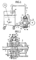
- a tank 1 for storing a liquid containing a material to be treated such as a slurry and a dispersing medium is preferably provided with an agitating blade 2 for stirring and mixing the contents of the tank as shown in the drawing, and a pipeline 3 disposed at the lower portion of the tank is connected to a sucking inlet 6 of a dispersing apparatus through a valve 4.
- the dispersing apparatus 5 has a structure basically the same as the rotary disc type dispersing apparatus as described in the above-mentioned Japanese Unexamined Patent Publication No. 7-116488, and comprises a plurality of discs 8a, 8b, 8c disposed within a dispersing chamber 7 of a substantially cylindrical shape, each of the discs being disposed with a certain distance, wherein a hole 10 is formed at the center portion of each of the discs 8a, 8b at the side of the sucking inlet 6 which opens at the center portion of a side plate 9, and connecting members 8d disposed at several portions around the hole 10 connect the discs 8a, 8b, 8c.
- the disc 8c is connected to an actuating shaft 11 and rotated by a motor 12 to rotate the discs entirely, and the liquid which is in contact with the surface of the disc is thereby made to flow in a circumferential direction by the action such as friction or centrifugal force to generate a sucking action, whereby the liquid to be treated is sucked into the dispersing chamber through the sucking inlet 6.
- a dispersing medium 13 such as glass beads, ceramics beads or steel balls, is charged in a predetermined amount into the tank 1, and sucked into the dispersing chamber through the sucking inlet 6 as disc rotates.
- the supply of the dispersing medium may be supplemented without stopping the operation of the dispersing apparatus.
- the dispersing medium 13 is given a motion by means of the discs 8a, 8b, 8c.
- the distance between the respective discs and the distance between each disc and the inner wall of the dispersing chamber is suitably maintained so that no jam or break is occurred for the dispersing medium.
- a medium-separating means for separating the dispersed liquid from the dispersing medium is formed.
- the medium-separating means is detachably disposed to the dispersing chamber so that the medium-separating means may be attached to the dispersing chamber during dispersion treatment, and may be detached from the diersing chamber during cleaning after completion of the dispersion treatment.
- the medium-separating means may be movably disposed between an operation position and a non-operation position within the dispersing chamber, or as described below, a flow path for permitting the dispersing medium to flow, may be disposed separately, to open and shut the flow path.
- a suitable separating means of e.g. a screen system. a cassette screen system or a gap separator system, may be used.
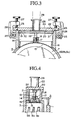
- Figs. 3 and 4 show an embodiment of the medium-separating means of a screen system, wherein a filter 15 having e.g. a slit, pores or a net, through which the dispersed liquid is permitted to pass and the dispersing medium is not permitted to pass, is formed in a shape along the inner surface of the dispering chamber 7, and is held by a holding frame 16 which is detachably engaged with a discharge outlet 14 of a substantially square shape in cross-section.
- a filter 15 having e.g. a slit, pores or a net, through which the dispersed liquid is permitted to pass and the dispersing medium is not permitted to pass, is formed in a shape along the inner surface of the dispering chamber 7, and is held by a holding frame 16 which is detachably engaged with a discharge outlet 14 of a substantially square shape in cross-section.
- a stay 17 is fixed to the substantially center portion of the holding frame 16, a connection rod 19 is fitted with a screw to a securing portion 18 disposed on the stay 17, and a securing frame 20 is fixed to other end of the connection rod 19.
- the securing frame 20 is detachably fitted to receiving grooves 21, 21 formed at the opening end of the discharge outlet 14, and the holding frame 16 is thereby held within the discharge outlet 14.
- a cover plate 24 which has, on its lower surface, a seal 23 and small projections 22, 22 which fit to the receiving grooves 21, 21 and press the securing frame 20.
- the cover plate 24 is fastened to a fastening screw 27 of a clamp 26 which is hinged by a hinge 25 to the dispersing chamber 7.
- the cover plate 24 is provided with a discharge pipeline 28.
- the dispersed liquid discharged from the discharge outlet 14 is discharged through the discharge pipeline 28, and pass through a pipeline 29 detachably connected to the discharge pipeline 28 and circulated to the tank 1.
- Figs. 5(A) and 5(B) show views illustrating an embodiment wherein a medium-separating means is fixedly disposed.
- a filter 30 having e. g. slits, a net or pores, through which the dispersed liquid is permitted to pass and the dispersing medium is not permitted to pass, is formed along the inner surface of the dispersing chamber.
- a flow path 31 wherein the dispersing medium flows is formed at the side portion of the filter 30, and an open-and-shut means for opening or shutting the flow path 31 is disposed.
- the open-and-shut means is a plate 32 slidably disposed in front of the filter 30 and the flow path 31, and if the flow path 31 is shut by the plate 32, the dispersed liquid is discharged through the filter 30 as shown in Fig. 5(A), by which the dispersing medium in the dispersing chamber is prevented from flowing out, and if the plate 32 is moved to shut the flow path 31, the dispersing medium is made to flow out (Fig. 5(B)).
- the terminal end of the pipeline 29 opens toward the tank 1, and against the terminal end, a collecting filter 33 having e.g. slits, a net or pores formed, is provided so that a cleaning liquid can be permitted to flow, but the dispersing medium can be collected.
- the collecting filter 33 is taken away from the position against the terminal end of the pipeline 29, and when the dispersing medium is collected, the collecting filter 33 is set at the position against the terminal end of the pipeline 29 as shown in Fig. 1.
- the liquid tcontaining a material to be treated and the dispersing medium 13 is charged into the tank 1 and then the dispersing apparatus 5 is actuated.
- the liquid to be treated and the dispersing medium are sucked into the dispersing chamber 7 through the pipeline 3, and then, the material is dispersed in the liquid by the dispersing medium which moves by the rotation of the discs 8a, 8b, 8c.
- the dispersed liquid is discharged from the discharge outlet 14 and returned to the tank I through the pipeline 29, though the dispersing medium remains in the dispersing chamber by means of the medium-separating means.
- the dispersing apparatus After completion of the dispersion treatment, the dispersing apparatus is stopped, and the liquid remaining in the dispersing chamber 7 or the pipeline 29 is taken out from a plug valve 34 disposed on the side plate 9, and then the medium-separating means is taken away from the discharge outlet or the flow path 31 for permitting the dispersing medium to flow is opened, and the line is arranged again, a cleaning liquid is charged into tank 1 and the dispersing apparatus 5 is operated.
- the dispersing medium in the dispersing chamber 7 is discharged from the dispersing chamber together with the cleaning liquid sucked in the dispersing chamber, circulated in the line, by which the dispersing medium is itself cleaned, and at the same time, by permitting the dispersing medium to flow all the corners of the tank, dispersing chamber, pipenine and the like, stains or the like adhered to every corner portions of the line can be removed by cleaning.
- the collecting filter 33 is set at the position against the terminal end of the pipeline 29, to collect only the dispersing medium within the filter.
- the dispersion method comprises sucking a liquid containing a material to be treated and a dispersing medium stored in a tank through a sucking inlet into a dispersing chamber by sucking action generated by rotation of a disc which is disposed in the dispersing chamber; constraining the dispersion medium within the dispersing chamber by a medium-separating means; dispersing the material in the liquid by moving the dispersing medium; discharging the dispersed liquid though a discharge outlet while separating the dispersing medium from the dispersed liquid by means of the medium-separating means; circulating the dispersed liquid to the tank through a pipeline which communicates from the discharge outlet to the tank; and after completion of dispersion treatment, cleaning the tank, dispersing chamber and pipeline by permitting the dispersing medium to flow out of the dispersing chamber through the discharge outlet, and to circulate together with a cleaning liquid through the tank, dispersing chamber and pipeline, by which even if the dispersing medium is not charged into the dispersing chamber at first,
- the dispersing medium can simply be taken out (discharge) of the dispersing chamber and the dispersing medium is circulated in the line together with the cleaning liquid, whereby the dispersing medium itself is cleaned and solid or liquid stains adhered to the inside of the tank or the dispersing chamber, or corner portions of the pipelines in which the liquid flows, can be completely removed by cleaning, and further it is easy to change the types or colors of products such as a coating material and it is possible to apply such method or apparatus to a small amount of production of various kinds.
Landscapes
- Chemical & Material Sciences (AREA)
- Chemical Kinetics & Catalysis (AREA)
- Engineering & Computer Science (AREA)
- Food Science & Technology (AREA)
- Dispersion Chemistry (AREA)
- Mixers Of The Rotary Stirring Type (AREA)
- Paper (AREA)
Claims (4)
- Dispergierungsverfahren, umfassend die nachfolgenden Schritte:dadurch gekennzeichnet, dassEinleiten einer Flüssigkeit, die ein zu behandelndes Material enthält, und eines Dispergierungsmittels in eine Dispergierungskammer (7),Dispergieren des Materials in der Flüssigkeit durch Bewegen des Gemisches der Flüssigkeit und des Dispergierungsmittels,Ableiten der dispergierten Flüssigkeit durch einen Ableitungsauslass (14), während dessen das Dispergierungsmittel von der dispergierten Flüssigkeit mittels einer Mittelabscheideeinrichtung (15) abgeschieden wird, undZirkulieren der dispergierten Flüssigkeit zu einem Tank (1) durch eine Rohrleitung (29), welche den Ableitungsauslass (14) der Dispergierungskammer (7) mit dem Tank kommunizierend verbindet,
zu Beginn des Dispergierungs-Zeitabschnitts die zu dispergierende Flüssigkeit und das Dispergierungsmittel (13) in die Dispergierungskammer durch einen Saugeinlass (6) der Dispergierungskammer (7) durch einen Saugvorgang gesaugt wird, der durch Drehen von zumindest einer Scheibe erzeugt wird, der die zu dispergierende Flüssigkeit auf den gewünschten Grad dispergiert, und dass
nach Beendigung der Dispergierungsbehandlung die dispergierte Flüssigkeit aus dem Tank abgeleitet wird,
eine Reinigungsflüssigkeit in den Tank gefüllt, die Abscheideeinrichtung (15) von dem Auslass (14) entfernt und das Dispergierungsmittel (13) mit der Reinigungsflüssigkeit durch den Auslass (14) der Dispergierungskammer (7) abgeleitet und das Dispergierungsmittel zusammen mit der Reinigungsflüssigkeit durch den Tank (1), die Dispergierungskammer (7) und die Rohrleitung als ein Ganzes zirkuliert wird, um dadurch alle Abschnitte der Fertigungsstraße zu reinigen. - Dispergierungsvorrichtung, umfassend
einen Tank (1), der über eine Rohrleitung (3) mit einem Saugeinlass (6) einer Dispergierungskammer (7) und über eine Rohrleitung (29) mit dem Ableitungsauslass (14) der Dispergierungskammer (7) verbunden ist, wobei eine Mittelabscheideeinrichtung (30) an dem Ableitungsauslass (14) zum Abscheiden eines Dispergierungsmittels von einer dispergierten Flüssigkeit vorgesehen ist und zumindest eine Scheibe (8) in der Dispergierungskammer (7) zum Dispergieren der zu dispergierenden Flüssigkeit auf den gewünschten Grad vorgesehen ist,
dadurch gekennzeichnet, dass
ein Strömungspfad (31) an einem Seitenabschnitt der Mittelabscheideeinrichtung (30) ausgebildet ist, durch welchen Strömungspfad ein Passieren des Dispergierungsmittels ermöglicht ist, und dass eine Öffnungs- und Schließeinrichtung (32) zum Öffnen oder Schließen des Strömungspfades an der Innenseite des Ableitungsauslasses (14) vorgesehen ist,
wobei während eines Dispergierungszeitabschnitts dispergierte Flüssigkeit durch die Mittelabscheideeinrichtung (30) passiert und während eines Reinigungszeitabschnitts, in welchem der Tank (1) mit einer Reinigungsflüssigkeit gefüllt wird, nachdem die dispergierte Flüssigkeit aus dem Tank (1) nach einer Dispergierungsbehandlung in der Dispergierungskammer (7) abgeleitet wird, das Dispergierungsmittel zusammen mit der Reinigungsflüssigkeit durch den Strömungspfad (31) nach Öffnen der Öffnungs- und Schließeinrichtung (32) passiert. - Dispergierungsvorrichtung gemäß Anspruch 2, wobei die Mittelabscheideeinrichtung einen Filter (15, 30) umfasst, durch welchen ein Passieren der dispergierten Flüssigkeit ermöglicht ist, und ein Passieren des Dispergierungsmittels nicht ermöglicht ist, und wobei ein Halterahmen (16) zum Halten des Filters (15, 30) umfasst, wobei der Halterahmen (16) in abnehmbarer Weise an dem Ende des Ableitungsauslasses (14) angeordnet ist.
- Dispergierungsvorrichtung gemäß Anspruch 3, wobei der Filter entlang der inneren Oberfläche der Dispergierungskammer (7) angeordnet ist, wenn der Halterahmen (16) an dem Ende des Ableitungsauslasses (14) angeordnet ist.
Applications Claiming Priority (3)
| Application Number | Priority Date | Filing Date | Title |
|---|---|---|---|
| JP24171797A JP3855213B2 (ja) | 1997-08-25 | 1997-08-25 | 分散方法及び分散機 |
| JP241717/97 | 1997-08-25 | ||
| JP24171797 | 1997-08-25 |
Publications (2)
| Publication Number | Publication Date |
|---|---|
| EP0899004A1 EP0899004A1 (de) | 1999-03-03 |
| EP0899004B1 true EP0899004B1 (de) | 2004-02-04 |
Family
ID=17078494
Family Applications (1)
| Application Number | Title | Priority Date | Filing Date |
|---|---|---|---|
| EP98105630A Expired - Lifetime EP0899004B1 (de) | 1997-08-25 | 1998-03-27 | Verfahren und Vorrichtung zum Dispergieren |
Country Status (9)
| Country | Link |
|---|---|
| US (1) | US6029853A (de) |
| EP (1) | EP0899004B1 (de) |
| JP (1) | JP3855213B2 (de) |
| KR (1) | KR100352990B1 (de) |
| CN (1) | CN1104943C (de) |
| DE (1) | DE69821416T2 (de) |
| ES (1) | ES2213234T3 (de) |
| MY (1) | MY118916A (de) |
| SG (1) | SG71752A1 (de) |
Families Citing this family (20)
| Publication number | Priority date | Publication date | Assignee | Title |
|---|---|---|---|---|
| US7674077B2 (en) * | 2007-12-04 | 2010-03-09 | Agassiz Fieldstone, Inc. | Method of transporting tuberous vegetables |
| WO2009154188A1 (ja) | 2008-06-16 | 2009-12-23 | アイセル株式会社 | 混合要素、混合装置、攪拌翼、混合機、混合システム及び反応装置 |
| WO2010011613A2 (en) * | 2008-07-21 | 2010-01-28 | Anthony Crivello | Portable hydroseeder |
| EP2676725B1 (de) | 2012-06-18 | 2016-03-02 | Bühler AG | Vorrichtung und Verfahren zum Mischen, insbesondere zum Dispergieren |
| CN102775848A (zh) * | 2012-07-31 | 2012-11-14 | 苏州中亚油墨有限公司 | 凹版溶剂油墨生产系统 |
| US9185840B2 (en) * | 2012-09-05 | 2015-11-17 | Anthony Michael Crivello | Portable direct current hydroseeder |
| JP5760205B2 (ja) * | 2013-04-23 | 2015-08-05 | アイセル株式会社 | 混合方法、混合装置、及び混合流体 |
| US20150209741A1 (en) * | 2014-01-27 | 2015-07-30 | ProMinent Fluid Controls, Inc. | Polymer Mixer |
| US9682494B2 (en) * | 2014-03-20 | 2017-06-20 | Amix Systems Ltd. | Colloidal mixing method for slurries |
| CN105413556B (zh) * | 2014-09-15 | 2018-04-24 | 广东雪莱特光电科技股份有限公司 | 一种氧化铝分散装置 |
| RU2699108C2 (ru) | 2015-04-17 | 2019-09-03 | Бюлер Аг | Устройство и способ для смешивания, в частности, для диспергирования |
| EP3229950B1 (de) | 2016-02-17 | 2018-07-18 | Bühler AG | Vorrichtung zum mischen, insbesondere zum dispergieren |
| JP6726003B2 (ja) * | 2016-03-10 | 2020-07-22 | 株式会社井上製作所 | スラリーの混練・分散装置 |
| CN106311019A (zh) * | 2016-08-30 | 2017-01-11 | 浙江安吉天洋滚塑设备有限公司 | 高效温控增压智能调节搅拌过滤罐 |
| RU2650974C1 (ru) * | 2016-11-09 | 2018-04-18 | Игорь Владимирович Подковыров | Комплекс для получения ультрадисперсных продуктов в жидкой среде |
| CN107583553B (zh) * | 2017-09-18 | 2020-06-23 | 岳阳中南利康医药科技有限公司 | 一种消毒药水混制装置 |
| CN109758933B (zh) * | 2019-03-14 | 2021-10-01 | 汕尾职业技术学院 | 一种墨水生产装置 |
| JP7516058B2 (ja) * | 2020-02-10 | 2024-07-16 | 日本スピンドル製造株式会社 | 分散装置及び粉体供給部材 |
| CN112958198B (zh) * | 2021-01-30 | 2022-08-19 | 山东中鹏食品科技有限公司 | 一种食用油加工中的研磨装置 |
| CN117482828B (zh) * | 2023-12-21 | 2024-03-22 | 北京洗得宝消毒制品有限公司 | 漱口水原料混合装置 |
Family Cites Families (16)
| Publication number | Priority date | Publication date | Assignee | Title |
|---|---|---|---|---|
| US2017867A (en) * | 1930-02-05 | 1935-10-22 | Merle E Nantz | Mixing device |
| US3095121A (en) * | 1960-10-20 | 1963-06-25 | Amchem Prod | Chemical feed control system |
| US3244328A (en) * | 1964-03-23 | 1966-04-05 | Corning Glass Works | Dispensing from plural sources |
| US3717285A (en) * | 1971-06-28 | 1973-02-20 | Sta Soil Corp | Apparatus for spraying a slurry |
| US4082227A (en) * | 1976-07-21 | 1978-04-04 | Bio-Life Company, Inc. | Slurry mixer and spreader |
| US4514139A (en) * | 1978-08-30 | 1985-04-30 | Gurth Max Ira | Method and apparatus for pumping fragile articles |
| US4335994A (en) * | 1978-08-30 | 1982-06-22 | Gurth Max Ira | Method and apparatus for pumping large solid articles |
| US4773819A (en) * | 1978-08-30 | 1988-09-27 | Gurth Max Ira | Rotary disc slurry pump |
| DE3013606A1 (de) * | 1980-04-09 | 1981-10-15 | Fa. Paul Vollrath, 5000 Köln | Ruehrwerkskugelmuehle |
| DD153331A1 (de) * | 1980-10-02 | 1982-01-06 | Wolfgang Haentzschel | Ruehrwerkskugelmuehle |
| US4391390A (en) * | 1981-01-21 | 1983-07-05 | Howard Arthur G | Chemical-mixing and dispensing apparatus |
| GB8700984D0 (en) * | 1987-01-17 | 1987-02-18 | Yorkshire Chemicals Ltd | Abrasive medium mill |
| JP2577301B2 (ja) * | 1993-06-30 | 1997-01-29 | 日精樹脂工業株式会社 | 混入磁性体の除去装置 |
| ATE171886T1 (de) * | 1993-07-12 | 1998-10-15 | Promotec Ag | Verfahren, zusammensetzung und vorrichtung zur innenreinigung und beschichtung von rohrleitungen |
| JP2898523B2 (ja) * | 1993-10-26 | 1999-06-02 | 日本ペイント株式会社 | 分散装置および分散方法 |
| DE4430334A1 (de) * | 1994-08-29 | 1996-03-07 | Gevi Gmbh | Verfahren zur Sanierung von Rohrleitungen |
-
1997
- 1997-08-25 JP JP24171797A patent/JP3855213B2/ja not_active Expired - Lifetime
- 1997-12-19 MY MYPI97006183A patent/MY118916A/en unknown
-
1998
- 1998-02-02 KR KR1019980002774A patent/KR100352990B1/ko not_active Expired - Lifetime
- 1998-02-03 SG SG1998000234A patent/SG71752A1/en unknown
- 1998-02-13 CN CN98104452A patent/CN1104943C/zh not_active Expired - Lifetime
- 1998-02-20 US US09/027,094 patent/US6029853A/en not_active Expired - Lifetime
- 1998-03-27 EP EP98105630A patent/EP0899004B1/de not_active Expired - Lifetime
- 1998-03-27 DE DE69821416T patent/DE69821416T2/de not_active Expired - Lifetime
- 1998-03-27 ES ES98105630T patent/ES2213234T3/es not_active Expired - Lifetime
Also Published As
| Publication number | Publication date |
|---|---|
| CN1104943C (zh) | 2003-04-09 |
| EP0899004A1 (de) | 1999-03-03 |
| CN1209354A (zh) | 1999-03-03 |
| MY118916A (en) | 2005-02-28 |
| JP3855213B2 (ja) | 2006-12-06 |
| SG71752A1 (en) | 2000-04-18 |
| KR19990023055A (ko) | 1999-03-25 |
| ES2213234T3 (es) | 2004-08-16 |
| JPH1157438A (ja) | 1999-03-02 |
| US6029853A (en) | 2000-02-29 |
| KR100352990B1 (ko) | 2002-12-11 |
| DE69821416T2 (de) | 2004-12-02 |
| DE69821416D1 (de) | 2004-03-11 |
Similar Documents
| Publication | Publication Date | Title |
|---|---|---|
| EP0899004B1 (de) | Verfahren und Vorrichtung zum Dispergieren | |
| KR100417748B1 (ko) | 습식 교반 볼 밀 및 분쇄 방법 | |
| KR100927949B1 (ko) | 바스켓 밀 | |
| US8002213B2 (en) | Agitator mill | |
| US6585180B2 (en) | Pipeline beads mill and dispersing system having the pipeline beads mill | |
| US5894998A (en) | Agitator mill | |
| CN101287554A (zh) | 搅拌式研磨机 | |
| US4106116A (en) | Dispersing apparatus | |
| JPH0669538B2 (ja) | 予め液体内に分散させた固体を粉砕および細砕するためのミル | |
| CN212068999U (zh) | 具有自清洁功能的卧式砂磨机 | |
| EP1072305B1 (de) | Dispersionsvorrichtung für Materialien | |
| JPH10230182A (ja) | 粉砕機 | |
| JPH105563A (ja) | 湿式微粒分散粉砕機 | |
| JP2000354780A (ja) | 媒体攪拌型粉砕機及びその洗浄装置と洗浄方法 | |
| JP3441802B2 (ja) | 微粉末粉砕用攪拌ミル | |
| US3352501A (en) | Grinding apparatus | |
| JPH11262646A (ja) | 分散装置 | |
| JP3246973B2 (ja) | 攪拌ミルを有する粉砕装置 | |
| CN219187189U (zh) | 一种立式介质研磨机构 | |
| JPH084114Y2 (ja) | 粉砕媒体補充装置を備える粉砕機 | |
| CN221245567U (zh) | 一种动态离心式砂磨机 | |
| CN223542809U (zh) | 一种粉末涂料预混料装置 | |
| JP6862020B1 (ja) | 分散システム | |
| CN211134141U (zh) | 一种锆珠研磨机 | |
| JPH025868Y2 (de) |
Legal Events
| Date | Code | Title | Description |
|---|---|---|---|
| PUAI | Public reference made under article 153(3) epc to a published international application that has entered the european phase |
Free format text: ORIGINAL CODE: 0009012 |
|
| AK | Designated contracting states |
Kind code of ref document: A1 Designated state(s): BE CH DE ES FR GB LI |
|
| AX | Request for extension of the european patent |
Free format text: AL;LT;LV;MK;RO;SI |
|
| 17P | Request for examination filed |
Effective date: 19990413 |
|
| AKX | Designation fees paid |
Free format text: BE CH DE ES FR GB LI |
|
| 17Q | First examination report despatched |
Effective date: 20010816 |
|
| GRAP | Despatch of communication of intention to grant a patent |
Free format text: ORIGINAL CODE: EPIDOSNIGR1 |
|
| GRAS | Grant fee paid |
Free format text: ORIGINAL CODE: EPIDOSNIGR3 |
|
| GRAA | (expected) grant |
Free format text: ORIGINAL CODE: 0009210 |
|
| AK | Designated contracting states |
Kind code of ref document: B1 Designated state(s): BE CH DE ES FR GB LI |
|
| PG25 | Lapsed in a contracting state [announced via postgrant information from national office to epo] |
Ref country code: BE Free format text: LAPSE BECAUSE OF FAILURE TO SUBMIT A TRANSLATION OF THE DESCRIPTION OR TO PAY THE FEE WITHIN THE PRESCRIBED TIME-LIMIT Effective date: 20040204 |
|
| REG | Reference to a national code |
Ref country code: GB Ref legal event code: FG4D |
|
| REG | Reference to a national code |
Ref country code: CH Ref legal event code: EP |
|
| REF | Corresponds to: |
Ref document number: 69821416 Country of ref document: DE Date of ref document: 20040311 Kind code of ref document: P |
|
| REG | Reference to a national code |
Ref country code: CH Ref legal event code: NV Representative=s name: SCHMAUDER & PARTNER AG PATENTANWALTSBUERO |
|
| REG | Reference to a national code |
Ref country code: ES Ref legal event code: FG2A Ref document number: 2213234 Country of ref document: ES Kind code of ref document: T3 |
|
| ET | Fr: translation filed | ||
| PLBE | No opposition filed within time limit |
Free format text: ORIGINAL CODE: 0009261 |
|
| STAA | Information on the status of an ep patent application or granted ep patent |
Free format text: STATUS: NO OPPOSITION FILED WITHIN TIME LIMIT |
|
| 26N | No opposition filed |
Effective date: 20041105 |
|
| REG | Reference to a national code |
Ref country code: CH Ref legal event code: PCAR Free format text: SCHMAUDER & PARTNER AG PATENT- UND MARKENANWAELTE VSP;ZWAENGIWEG 7;8038 ZUERICH (CH) |
|
| REG | Reference to a national code |
Ref country code: FR Ref legal event code: PLFP Year of fee payment: 18 |
|
| REG | Reference to a national code |
Ref country code: FR Ref legal event code: PLFP Year of fee payment: 19 |
|
| REG | Reference to a national code |
Ref country code: FR Ref legal event code: PLFP Year of fee payment: 20 |
|
| PGFP | Annual fee paid to national office [announced via postgrant information from national office to epo] |
Ref country code: FR Payment date: 20170323 Year of fee payment: 20 Ref country code: CH Payment date: 20170323 Year of fee payment: 20 Ref country code: DE Payment date: 20170323 Year of fee payment: 20 |
|
| PGFP | Annual fee paid to national office [announced via postgrant information from national office to epo] |
Ref country code: GB Payment date: 20170323 Year of fee payment: 20 |
|
| PGFP | Annual fee paid to national office [announced via postgrant information from national office to epo] |
Ref country code: ES Payment date: 20170328 Year of fee payment: 20 |
|
| REG | Reference to a national code |
Ref country code: DE Ref legal event code: R071 Ref document number: 69821416 Country of ref document: DE |
|
| REG | Reference to a national code |
Ref country code: GB Ref legal event code: PE20 Expiry date: 20180326 |
|
| REG | Reference to a national code |
Ref country code: CH Ref legal event code: PL |
|
| PG25 | Lapsed in a contracting state [announced via postgrant information from national office to epo] |
Ref country code: GB Free format text: LAPSE BECAUSE OF EXPIRATION OF PROTECTION Effective date: 20180326 |
|
| REG | Reference to a national code |
Ref country code: ES Ref legal event code: FD2A Effective date: 20200723 |
|
| PG25 | Lapsed in a contracting state [announced via postgrant information from national office to epo] |
Ref country code: ES Free format text: LAPSE BECAUSE OF EXPIRATION OF PROTECTION Effective date: 20180328 |