EP0899062A2 - Elément de machine - Google Patents
Elément de machine Download PDFInfo
- Publication number
- EP0899062A2 EP0899062A2 EP98114789A EP98114789A EP0899062A2 EP 0899062 A2 EP0899062 A2 EP 0899062A2 EP 98114789 A EP98114789 A EP 98114789A EP 98114789 A EP98114789 A EP 98114789A EP 0899062 A2 EP0899062 A2 EP 0899062A2
- Authority
- EP
- European Patent Office
- Prior art keywords
- machine element
- oval
- element according
- stops
- oval body
- Prior art date
- Legal status (The legal status is an assumption and is not a legal conclusion. Google has not performed a legal analysis and makes no representation as to the accuracy of the status listed.)
- Withdrawn
Links
Images

Classifications
-
- B—PERFORMING OPERATIONS; TRANSPORTING
- B25—HAND TOOLS; PORTABLE POWER-DRIVEN TOOLS; MANIPULATORS
- B25B—TOOLS OR BENCH DEVICES NOT OTHERWISE PROVIDED FOR, FOR FASTENING, CONNECTING, DISENGAGING, OR HOLDING
- B25B5/00—Clamps
- B25B5/06—Arrangements for positively actuating jaws
- B25B5/08—Arrangements for positively actuating jaws using cams
Definitions
- the invention is in the field of machine elements and relates in particular a machine element with a frame and movable Stops for generating a lifting movement from a rotation, for Example for clamping or clamping.
- Such machine elements are widely known. To create in most cases an eccentric is used for the lifting movement the extension of the lifting movement up to almost 360 degrees of rotation allowed if that is desired and a stop to prevent it the rotation is provided.
- a subset of such Machine elements use a body instead of an eccentric oval cross-section, this also from a body with circular cross-section may exist opposite the axis of rotation is staggered. The machine elements of this sub-group only have a rotation angle of 90 degrees.
- the grip is with a in a guide housing adjustable in length in the direction of tension Clamping unit formed with a in the tubular guide housing provided, longitudinally displaceable pressure stamp cooperates, the front end of which protrudes from the guide housing.
- the clamping unit has an axis arranged transversely to the guide housing swiveling clamping lever with one for advancing the pressure stamp a rigid assembly in the direction of the cam forms.
- the tubular guide housing has the pressure stamp in it part facing away a fixed abutment stamp with its free end supported against a fixed clamping abutment is.
- the end of the abutment plunger located in the guide housing is fork-shaped and partially embraces the tensioning lever, its pivot axis across the fork-shaped end of the abutment pin and the guide housing is inserted through.
- the invention has set itself the task of a machine element to provide a generic type of training which is considerably simpler and more effective, so it’s less expensive to manufacture, less Has space requirements and is also easier to assemble and maintain.
- a machine element of the generic type Kind of characterized in that the oval body by one too its central axis parallel shaft rotatable against one hand frame-fixed stop on the other hand against a sliding stop is applied and with its rotating shaft in one direction between two stops is slidably mounted.
- This arrangement according to the invention ensures that the displacement or. Clamping forces between the two stops only work over the oval clamping body and from this to the machine frame be directed. There are no additional bearings, their precise manufacturing and load calculation required. It is also possible. the oval clamping body in a very simple way and Way of exchanging for another with a different shape or dimensions, if that is desired or if the same item is on should be used in different places where different Strokes can be generated without anything else change is. The length of the movable storage must of course the stroke length or the eccentricity of the oval clamping body used correspond, but there is no upper limit. because the movement of the body is limited by the stops on both sides is.
- the rotary shaft is oval Body in one, extending at least between the two stops Elongated hole stored.
- This slot requires no particular precision, it can be as long as you like yes, as I said, the shifting movement of the oval body is limited by the stops on both sides.
- the rotary shaft of the oval body stored in a housing in which the two stops are guided and movable relative to both attacks is.
- This embodiment offers the advantage, for example, that the sliding movement that occurs when the oval body rotates is generated, both by the movable stop and by the Housing can be derived, in a certain ratio, that depends on the shape or design of the oval body is.
- the general construction of the machine element made only a very minor change, ultimately only omitting the fixed connection between the housing and the firm stop.
- the oval body an elliptical cross section. This ensures that a uniform lifting movement occurs when it rotates by 90 degrees. If according to another embodiment of the invention, the oval body has a flat oval cross-section, when rotating it is initially one use greater force. For example, for security reasons be desired.
- the oval Body flattened at the apex of its strongest curvatures. Thereby a rest or dead position is generated, an unwanted reverse rotation from the unstable situation, for example due to machine vibrations, is prevented.
- the fixed stop adjustable for example to adjust the stroke particularly fine.
- the movable Spring-loaded stop pressed against the oval body be. This means that the oval body in everyone Location, regardless of gravity, between its two stops is held securely, it can also be a rest position of the movable Stop.
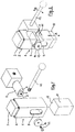
- a Housing 1 consisting of a tube section with a square cross section, is at its upper end 2 by means of one, the entire inner Cross-section filling plug 3 closed.
- the inner, flat surface of this plug 3 forms an upper stop fixed to the housing 4, against which a body 5 with an oval cross section 6 rests.
- This body 5 is freely movable in the cross section of the housing 1 inserted, it is provided with a rotary shaft 7 at both ends of the oval cross section protrudes from the body and parallel or runs straight to its central axis 8.
- This rotary shaft 7 is in the housing 1 on both sides of the oval body guided into the housing 1 through elongated holes 9.
- the Elongated holes 9 extend from the inner surface 4 of the plug 3, that is, from the frame-fixed stop of the oval body 5 downwards up to the upper contact surface one can be moved into the housing from below inserted plug 10, which is the housing-fixed plug 3rd opposite stop 11 for the oval body 5 forms.
- these elongated holes 9 are approximately these must have the prescribed minimum length, otherwise in length don't need to be limited.
- the housing 1 can two opposing U-profiles exist, on their Long sides limit the elongated holes. These U profiles are on yours the upper end is held in the required position by the fixed plug 3, they can pass through a folded sleeve at their lower end or cuff.
- the lower stopper 10 with the stop 11 is in the housing 1 in Direction of arrows A freely movable, it can under the action of a Spring not shown here with its stop surface 11 constantly be pressed against the oval body when there is no other force is that pushes him like that.
- the oval body 5 can be rotated by at least 90 ° by means of this lever 12 in his constant plant against his two attacks 4 and 11. At such a rotation shifts its rotary shaft 7 within the Elongated holes 9, in which it is slidably mounted.
- the Rotation of the oval body between its two stops from the in Fig. 2 shown location where the smallest cross section of the oval body is between the two stops gradually come larger Cross cuts between the stops 4 and 11. With support the oval body moves downward against the fixed stop 4 and with it its slidably mounted shaft in the elongated holes 9.
- the fixed stop 4 also compared to an increase in cross section corresponds to the movable stop 11, this stop 11 shifted downwards, it can protrude from its housing 1 Side this shift, for example, as a clamping or clamping force be removed.
- the shaft 7 of the oval body 5 is on the the operating lever 12 opposite side of the housing 1 by means of a screw 13 and washer 14 secured.
- the rotary shaft can in any arranged parallel to the main axis of the oval cross-section be the oval body, with its rotating shaft in the elongated holes performed, when it rotates between the adjacent stops, in in any case from a layer with its smallest cross section into one Position with its largest cross-section and thereby the Hub generated between the two stops.
- Fig. 4-6 show another embodiment of the invention (thereby largely the same reference numerals are used for the same parts).
- the one-sided stop 4a forms for the oval body 5
- a housing 1a is slidably mounted.
- the housing 1a has an inner cross section which is the cross section of the plug or stamp 3 fixed to the frame and a slight shift compared to this stamp allowed, as well also the recording of the oval body and its pivoting.
- the oval body with its rotating shaft is appropriately dimensioned circular holes in the walls of the housing 1a rotatable and thus slidably mounted relative to the plug or fixed to the frame Stamp.
- a Plug or stamp 10a slidably mounted with its end face forms the counter-stop 11a for the oval body.
- an oval body is included elliptical cross section used. So that's the case performed stroke C half as large as the stroke A of the movable stop 11a. Due to the storage of the oval body in the movable The housing is movably mounted. According to this embodiment can be two coordinated and interdependent Lift movements are generated with a single swivel movement.
- the Invention can be particularly interesting, the rotating shaft of the oval body to be arranged outside of its main axis parallel to this Vary the ratio of the two strokes to each other.
Landscapes
- Engineering & Computer Science (AREA)
- Mechanical Engineering (AREA)
- Clamps And Clips (AREA)
- Transmission Devices (AREA)
- Forklifts And Lifting Vehicles (AREA)
Applications Claiming Priority (2)
| Application Number | Priority Date | Filing Date | Title |
|---|---|---|---|
| DE1997137032 DE19737032C1 (de) | 1997-08-26 | 1997-08-26 | Maschinenelement |
| DE19737032 | 1997-08-26 |
Publications (2)
| Publication Number | Publication Date |
|---|---|
| EP0899062A2 true EP0899062A2 (fr) | 1999-03-03 |
| EP0899062A3 EP0899062A3 (fr) | 2000-11-08 |
Family
ID=7840151
Family Applications (1)
| Application Number | Title | Priority Date | Filing Date |
|---|---|---|---|
| EP98114789A Withdrawn EP0899062A3 (fr) | 1997-08-26 | 1998-08-06 | Elément de machine |
Country Status (2)
| Country | Link |
|---|---|
| EP (1) | EP0899062A3 (fr) |
| DE (1) | DE19737032C1 (fr) |
Cited By (1)
| Publication number | Priority date | Publication date | Assignee | Title |
|---|---|---|---|---|
| DE10024524A1 (de) * | 2000-05-18 | 2001-11-29 | Manfred Fischer | Spannvorrichtung für ein Bearbeitungswerkzeug, insbesondere für ein Hand- oder Fußbehandlungswerkzeug |
Family Cites Families (7)
| Publication number | Priority date | Publication date | Assignee | Title |
|---|---|---|---|---|
| DE8318930U1 (de) * | 1984-04-19 | KEUCO Paul Keune GmbH & Co KG, 5870 Hemer | Wandhalter für eine Armatur | |
| DE723978C (de) * | 1940-10-22 | 1942-08-14 | Alfred Kraemer | Schnellspannanordnung mit Doppelspiralkeil |
| GB554147A (en) * | 1942-03-02 | 1943-06-22 | Paul Grodzinski | Improvements in cam clamping devices |
| GB617053A (en) * | 1944-12-20 | 1949-01-31 | F I S P A Fabbrica Itallana Sp | Improvements in and relating to quick pitch screw vice |
| DE1218949B (de) * | 1964-07-16 | 1966-06-08 | Otto Kreibaum | Spannvorrichtung fuer Plattenstapel, insbesondere fuer Schnittholzstapel |
| FR2242894A5 (en) * | 1973-08-30 | 1975-03-28 | Boismenu Marcel | Jack with central rotary shaft - non-circular rollers are rotated to move two axially spaced bearing rings apart |
| US4882921A (en) * | 1988-12-01 | 1989-11-28 | Frank Wopinski | King pin lock |
-
1997
- 1997-08-26 DE DE1997137032 patent/DE19737032C1/de not_active Expired - Fee Related
-
1998
- 1998-08-06 EP EP98114789A patent/EP0899062A3/fr not_active Withdrawn
Cited By (1)
| Publication number | Priority date | Publication date | Assignee | Title |
|---|---|---|---|---|
| DE10024524A1 (de) * | 2000-05-18 | 2001-11-29 | Manfred Fischer | Spannvorrichtung für ein Bearbeitungswerkzeug, insbesondere für ein Hand- oder Fußbehandlungswerkzeug |
Also Published As
| Publication number | Publication date |
|---|---|
| EP0899062A3 (fr) | 2000-11-08 |
| DE19737032C1 (de) | 1999-03-18 |
Similar Documents
| Publication | Publication Date | Title |
|---|---|---|
| EP0850119B1 (fr) | Outil d'ebarbage pour ebarber le bord de trous | |
| EP3201050B1 (fr) | Languette de boucle munie d'une barre de torsion | |
| EP0029498A1 (fr) | Serrure cylindrique avec clé plate | |
| DE19600031C2 (de) | Vertikal einstellbarer Maschinenträger | |
| DE202018102210U1 (de) | Verstellmechanismus und Hebevorrichtung, welche den Verstellmechanismus umfasst | |
| DE3244137A1 (de) | Vorrichtung zur schrittweisen einstellung der relativlagen fuer zwei in beziehung zueinander verschiebbare elemente | |
| EP3103948B1 (fr) | Penture pour une porte ou une fenêtre | |
| AT407551B (de) | Tür- oder fensterband | |
| DE69904408T2 (de) | Schlüssel mit bewegbarem stift, sicherheitsdrehzylinder und damit ausgerüstetes schloss | |
| WO2000014371A1 (fr) | Charniere a visser comportant une position d'arret | |
| DE29622727U1 (de) | Stanz- und Bindevorrichtung | |
| EP0207059B1 (fr) | Dispositif de fermeture pour classeur | |
| DE4125706C1 (fr) | ||
| DE19737032C1 (de) | Maschinenelement | |
| EP0597947B1 (fr) | Systeme d'arret, notamment pour des charnieres de portieres de vehicules automobiles | |
| DE102009051594B4 (de) | Haken, insbesondere für Sicherheitseinrichtungen | |
| CH651358A5 (de) | Vorrichtung zur befestigung eines laenglichen teils an einem maschinen- oder geraeteteil. | |
| DE2514078C3 (de) | Mehrfarbenkugelschreiber mit Drehbleistifteinsatz | |
| DE102018115924A1 (de) | Stuhl | |
| CH715123A1 (de) | Klappvorrichtung zur schwenkbaren Befestigung von Tischbeinen an einer Tischplatte. | |
| DE4211796C2 (de) | Vorrichtung zum Verbinden und Verriegeln zweier Elemente | |
| EP0524636A1 (fr) | Charnière pour portes, fenêtres ou similaires et élément de guidage pour la broche d'une telle ferrure | |
| DE9307622U1 (de) | Instrument für chirurgische Zwecke | |
| DE1654734B2 (de) | Klappenhalter | |
| DE102024125460A1 (de) | Rohrschneiderkonstruktion |
Legal Events
| Date | Code | Title | Description |
|---|---|---|---|
| PUAI | Public reference made under article 153(3) epc to a published international application that has entered the european phase |
Free format text: ORIGINAL CODE: 0009012 |
|
| AK | Designated contracting states |
Kind code of ref document: A2 Designated state(s): AT BE CH DE DK ES FI FR GB IT LI NL SE |
|
| AX | Request for extension of the european patent |
Free format text: AL;LT;LV;MK;RO;SI |
|
| PUAL | Search report despatched |
Free format text: ORIGINAL CODE: 0009013 |
|
| AK | Designated contracting states |
Kind code of ref document: A3 Designated state(s): AT BE CH CY DE DK ES FI FR GB GR IE IT LI LU MC NL PT SE |
|
| AX | Request for extension of the european patent |
Free format text: AL;LT;LV;MK;RO;SI |
|
| RIC1 | Information provided on ipc code assigned before grant |
Free format text: 7B 25B 5/08 A, 7B 23Q 3/06 B, 7F 16H 25/18 B |
|
| 17P | Request for examination filed |
Effective date: 20010307 |
|
| AKX | Designation fees paid |
Free format text: AT BE CH DE DK ES FI FR GB IT LI NL SE |
|
| 17Q | First examination report despatched |
Effective date: 20021115 |
|
| STAA | Information on the status of an ep patent application or granted ep patent |
Free format text: STATUS: THE APPLICATION IS DEEMED TO BE WITHDRAWN |
|
| 18D | Application deemed to be withdrawn |
Effective date: 20030326 |