EP0899088B1 - Compacteur de déchets ayant un dispositif d'éjection de balles - Google Patents
Compacteur de déchets ayant un dispositif d'éjection de balles Download PDFInfo
- Publication number
- EP0899088B1 EP0899088B1 EP98116417A EP98116417A EP0899088B1 EP 0899088 B1 EP0899088 B1 EP 0899088B1 EP 98116417 A EP98116417 A EP 98116417A EP 98116417 A EP98116417 A EP 98116417A EP 0899088 B1 EP0899088 B1 EP 0899088B1
- Authority
- EP
- European Patent Office
- Prior art keywords
- press
- rear wall
- shaft
- waste material
- guide
- Prior art date
- Legal status (The legal status is an assumption and is not a legal conclusion. Google has not performed a legal analysis and makes no representation as to the accuracy of the status listed.)
- Expired - Lifetime
Links
- 239000002699 waste material Substances 0.000 title claims description 30
- 230000008878 coupling Effects 0.000 claims abstract description 13
- 238000010168 coupling process Methods 0.000 claims abstract description 13
- 238000005859 coupling reaction Methods 0.000 claims abstract description 13
- 238000013016 damping Methods 0.000 claims description 3
- 238000013461 design Methods 0.000 claims description 3
- 238000003825 pressing Methods 0.000 description 16
- 239000003637 basic solution Substances 0.000 description 12
- 210000002414 leg Anatomy 0.000 description 9
- 238000011161 development Methods 0.000 description 5
- 230000018109 developmental process Effects 0.000 description 5
- 239000000243 solution Substances 0.000 description 5
- 239000002585 base Substances 0.000 description 3
- 239000000945 filler Substances 0.000 description 3
- 238000002360 preparation method Methods 0.000 description 3
- 230000006835 compression Effects 0.000 description 2
- 238000007906 compression Methods 0.000 description 2
- 238000010276 construction Methods 0.000 description 2
- 238000007726 management method Methods 0.000 description 2
- 239000000463 material Substances 0.000 description 2
- 239000005022 packaging material Substances 0.000 description 2
- 230000004913 activation Effects 0.000 description 1
- 238000013459 approach Methods 0.000 description 1
- 239000011888 foil Substances 0.000 description 1
- 238000012423 maintenance Methods 0.000 description 1
- 238000000034 method Methods 0.000 description 1
- 239000013641 positive control Substances 0.000 description 1
- 230000036544 posture Effects 0.000 description 1
- 210000000689 upper leg Anatomy 0.000 description 1
Images

Classifications
-
- B—PERFORMING OPERATIONS; TRANSPORTING
- B30—PRESSES
- B30B—PRESSES IN GENERAL
- B30B9/00—Presses specially adapted for particular purposes
- B30B9/30—Presses specially adapted for particular purposes for baling; Compression boxes therefor
- B30B9/3003—Details
- B30B9/3014—Ejection means
Definitions
- the invention relates to a waste press with ejection device according to the preamble of claim 1, in the cardboard boxes, foils and similar consumed Packaging materials are pressed into bales.
- Waste presses are already known with an ejection device, in the bottom area of the shaft of the press have a pivotable to the door opening lifting plate.
- the drive device for the lifting movement for pivoting said lifting plate is outside in these waste presses arranged on the rear wall of the press housing.
- the components for connecting the lifting plate to the drive unit are there by one in the back wall of the press housing provided, down to the pressing area reaching slot or slots through to the outside see US-A-4,311,092.
- This kind of Ejectors are due to the hydraulic and the additionally to be provided safety circuits in the control program cost and maintenance intensive, besides, can through the reaching down into the pressing area Slot to be pressed materials to the outside or Clogging cases often occur through blockages of the slot which reduce the effective utilization of the press.
- the Applicant has in the past, among others Ejection devices provided on balers, the one bottom-side lifting plate, one in the shaft of the press in or on the rear wall substantially vertically movable, with the lifting plate articulated connected traction means, preferably a pull rod, having, after open Front door in the area of the rear wall on the top of the Preßplatte arranged, pivotable or movable Driving part at the upper end of said traction means can be manually hooked into an eye. Between Press plate and rear wall located, compressed packaging material there makes it difficult to hook the entrainment part.
- the operator must press the press to operate the said entrainment part attached to the bale Position of the press plate over selbige over and to the with the press plate connected punch laterally over grab, with the operator usually with his upper body gets into the shaft of the press; while of the work step must safety circuits in the Control program unintentional operation of the Absolutely prevent pressure plate.
- the traction means preferably the Zustange, with and the bottom-side lifting plate is for ejecting the finished, tied bales in the direction of the released Door opening tilted; in preparation for the next Pressing must the pressing plate to turn off the Ejector for the time being again in the lower position and then be driven up again.
- the invention therefore has the task of a waste press to provide with ejector for bales, in which the above disadvantages are essentially no longer are present and in their constructive structure robust, prone to interference and inexpensive and more Improvements in the working conditions of the operator guaranteed.
- this object solves a waste press with ejection device for bales according to claim 1 or according to claim 2; the subordinate claims 3 to 12 disclose advantageous developments or variants of these two inventive basic solutions.
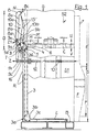
- a waste press after the first basic solution a press housing G, with a left side wall S1, a right side wall S2, a rear wall R, a Front door F, with integrated filler flap, and one Bottom surface B, and one surrounded by the press housing Shaft S, with at least one pressing area P and a above filling area E, is on the bottom surface B a tiltable lifting plate 2 and in the pressing area P of the shaft S, in the up to the bottom surface B reaching vertical groove N of the rear wall R, one with the Lifting plate 2 articulated by a hinge 3b
- Pull rod 3 arranged according to the present new Type with its upper end into the filling area E ranges and there with an outwardly projecting leg 3d equipped and fortified by a 3d in the latter Bar 16 is secured against falling into the shaft.
- the pull rod 3 of the ejector 1 temporarily with the pressing plate C connecting, otherwise tilted in a known manner on the top of the press plate C arranged so-called Coupling, is in the present embodiment by the novel connection unit of the ejection device 1 replaced.
- This new connection unit exists from a pivoting piece 4, that with a shaft 5 at the top End of the drawbar 3 hinged and with a Mit fortunebolzen 6 and a pressure pin 7 is provided from an upper U-shaped guide member 8 with preferably long thighs 8a and 8b, the one upper Section 10a form, and a lower also U-shaped Guide member 9 with preferably short legs 9a and 9b forming a lower portion 10b, wherein the Ends of the legs 8a, 8b and 9a, 9b of the two guide parts 8 and 9 facing each other and slightly overlapping one jointly closed, mobile guide 10 for form the pressure pin 7 secured in the swivel piece 4.
- the guide members 8 and 9 are each provided with a shaft 8c or 9c on the outside of the rear wall R hinged.
- to increase the stability of the outer Legs 8a and 9a in the overlapping end portions with interlocking pin 9e or slot 8d equipped become.
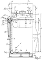
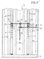
- FIG. 1 shows that with the front door F closed, the push rod 12 is engaged in the direction of arrow Z and the guide means 8 and 9 of the new connection unit of the ejector 1 in the direction of arrow Z1 position 'rest' held.
- the pivoting piece 4 is pulled by the guided pressure pin 7 to the rear; which is also provided on the pivot piece 4 driving pin 6 is swung out of the in the rear wall R vertically extending groove N.
- the pressing plate C is freely movable in the direction of arrows U and V in the shaft S.
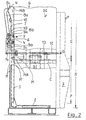
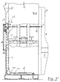
- the front door F is open, the push rod 12 moves in the direction of arrow O and pushes the guide members 8 and 9 in the direction of the rear wall R, the guided Pressure pin 7 pivots simultaneously the pivoting piece 4 together with the driving pin 6 in the direction of arrow Y through the opening D in the rear wall R, in the position -Ausier-, a.
- the laterally from the opening D on the outside of the rear wall R provided track 15 limits the pivotal movement of the pivoting piece 4 so that the driving pin 6 in the groove N along the line of movement MB of the end portion M 'of the driver M is located.
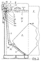
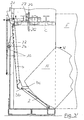
- the step 'ejection' is shown.
- the press plate C together with the driver M moves in the direction of arrow U upwards.
- the end portion M 'of the driver M engages under the driving pin 6, whereby the pull rod 3 are raised including the lifting plate 2.
- the lifting plate 2 pivots in the direction of door opening and the bale A is ejected in the direction of arrow W from the pressing region P of the shaft S and tilts to a previously positioned, not shown here transport pallet.
- the lower end of the drawbar 3 is equipped with a nose 3c pointing horizontally and in the direction of the lifting plate 2, which substantially accelerates the ejection of the bale A.
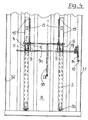
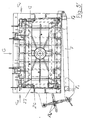
- Figs. 4 and 6 show a modified embodiment of the subject of the application.
- the ejection device 1 is with several, smaller lifting plates 2, each with one said drawbar 3 and each having a range of each a breakthrough D to D 'arranged connection unit 4 to 10b, equipped by the front door F operated adjusting means 12 and 14 by means of a Lever 19 on a common shaft 9c rotate, on 9c, the respective lower guide parts 9 fixedly arranged are.
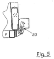
- a development of the invention still consists in that the front door F of the press housing G in fully open Position is applied to a safety switch 20, this safety switch 20 is the switch for the Press plate stroke releases, in the way, that only when fully open front door F a Release for the activation of the work step 'Bale ejection' can take place.
- the first Basic solution analogue execution form of a waste press has also on the bottom surface B a tiltable lifting plate.
- the second basic solution according to claim 2 lies mainly in the fact that instead of a rod guide now only the mechanically acting guide designed as two-armed pivot lever 21 and via the coupling rod 23 of the push rod 12 in conjunction with a cross bar (connecting rod 25), the rear wall stop 22 and the guideways 15 on the press rear wall R controllable in its entry and exit movement is.
- the bale ejection process also works in principle in the second new solution alike, as in the first new basic solution and also results from the associated figures 1 to 5 in conjunction with the preceding, associated description parts and the relevant items from the list of reference numerals.
Landscapes
- Engineering & Computer Science (AREA)
- Mechanical Engineering (AREA)
- Presses And Accessory Devices Thereof (AREA)
- Paper (AREA)
- Processing Of Solid Wastes (AREA)
- Refuse Collection And Transfer (AREA)
- Press Drives And Press Lines (AREA)
Claims (12)
- Compacteur de déchets doté d'un dispositif d'éjection de balles, dans le cas duquel sont disposées sur ou dans une surface de base (B) d'une caisse (S) formée par la carrosserie (G) de la presse au moins une plaque élévatrice basculante (2) et, dans la zone de compression (P) de la caisse (S), sur ou dans une paroi arrière (R), au moins une tige de traction (3) du dispositif d'éjection (1) qui est reliée de façon articulée à la plaque élévatrice (2), et sont prévus une pièce d'accouplement reliant au moins par moments la tige de traction (3) et la plaque de compression (C) et un moyen de commande pouvant être actionné à travers la porte frontale (F) de la carrosserie (G) de la presse et agissant indirectement ou directement sur la pièce d'accouplement, caractérisé en ce que la pièce d'accouplement transmettant par moments le mouvement de la plaque de compression (C, M, M') à la plaque élévatrice basculante (2) du dispositif d'éjection (1) est réalisée en tant qu'unité de liaison (4 à 10b) située à l'extérieur sur la paroi arrière (R) de la carrosserie (G) de la presse et passant en partie à travers un passage (D) ménagé dans ladite paroi arrière (R), que l'on peut faire rentrer et sortir en la faisant pivoter de force et qui agit par moments sur la plaque de compression (C, M, M'), qui comprend en outre des moyens de guidage mécaniques et agit de façon articulée à l'extrémité supérieure de la tige de traction (3), et en ce que l'unité de liaison (4 à 10b) et les moyens de guidage sont conçus en tant que tringlerie, sachant que l'unité de liaison (4 à 10b) est composée d'un élément pivotant (4) relié de façon articulée à la tige de traction (3) au moyen d'un arbre (5), sur lequel sont en outre prévus une broche d'entraínement (6) et un axe ou boulon de pression (7), d'un élément de guidage inférieur en forme de U (9) et d'un élément de guidage supérieur en forme de U (8) qui sont chacun montés de façon articulée par le biais d'un arbre (respectivement 9c et 8c) sur la face extérieure de la paroi arrière (R) dans la zone du passage (D) et qui forment ensemble un guide déplaçable fermé (10) pour l'axe de pression (7).
- Compacteur de déchets doté d'un dispositif d'éjection de balles, dans le cas duquel sont disposées sur ou dans une surface de base (B) d'une caisse (S) formée par la carrosserie (G) de la presse au moins une plaque élévatrice basculante (2) et, dans la zone de compression (P) de la caisse (S), sur ou dans une paroi arrière (R), au moins une tige de traction (3) du dispositif d'éjection (1) qui est reliée de façon articulée à la plaque élévatrice (2), et sont prévus une pièce d'accouplement reliant au moins par moments la tige de traction (3) et la plaque de compression (C) et un moyen de commande pouvant être actionné à travers la porte frontale (F) de la carrosserie (G) de la presse et agissant indirectement ou directement sur la pièce d'accouplement, caractérisé en ce que la pièce d'accouplement transmettant par moments le mouvement de la plaque de compression (C, M, M') à la plaque élévatrice basculante (2) du dispositif d'éjection (1) est réalisée en tant qu'unité de liaison (4 à 10b) située à l'extérieur sur la paroi arrière (R) de la carrosserie (G) de la presse et passant en partie à travers un passage (D) ménagé dans ladite paroi arrière (R), que l'on peut faire rentrer et sortir en la faisant pivoter de force et qui agit par moments sur la plaque de compression (C, M, M'), qui comprend en outre des moyens de guidage mécaniques et agit de façon articulée à l'extrémité supérieure de la tige de traction (3), et en ce que l'élément d'accouplement est prévu en tant que mécanisme à levier pivotant, le moyen de guidage à action mécanique étant réalisé en tant que levier pivotant à deux bras (21) et disposé de telle sorte que le mouvement de pivotement rentrant et sortant de ce dernier (21) peut être commandé par le biais de la bielle (23) de la tige de poussée (12) en relation avec une traverse (barre de liaison 25), avec une butée de paroi arrière (22) et avec les glissières de guidage (15) sur la face arrière de la presse (R).
- Compacteur de déchets doté d'un dispositif d'éjection de balles selon la revendication 1, caractérisé en ce que ladite unité de liaison (4 à 10b) avec le passage (D) sont disposés à l'extérieur, au-dessus de la zone de compression (P), dans la zone de remplissage (E) de la caisse (S), sur ou en partie dans la paroi arrière (R), et en ce qu'à côté du passage (D), à l'extérieur sur la paroi arrière (R) est prévue au moins une glissière de guidage (15) agissant sur des éléments de l'unité de liaison (4 à 10b), qui, vu de bas en haut, s'étend en biais vers l'extérieur dans sa partie supérieure.
- Compacteur de déchets doté d'un dispositif d'éjection de balles selon au moins l'une des revendications 1 à 3, caractérisé en ce que les moyens de commande influencés par le mouvement de la porte frontale (F) sont réalisés en tant que tige de poussée (12) soumise à la pression d'un ressort (13) et guidée dans ou sur une paroi latérale (S1 ou S2) de la carrosserie de la presse (G) et en tant qu'entretoise (14) ou bras de levier (24) reliant ladite tige de poussée (12) à l'un des moyens de guidage de l'unité de liaison.
- Compacteur de déchets doté d'un dispositif d'éjection de balles selon au moins l'une des revendications 1 à 4, caractérisé en ce que les moyens de commande influencés par le mouvement de la porte frontale (F) sont réalisés en tant que tige de poussée (12) soumise à la pression d'un ressort (13) et guidée dans ou sur une paroi latérale (S1 ou S2) de la carrosserie de la presse (G) et en tant qu'entretoise (14) ou bras de levier (24) reliant ladite tige de poussée (12) à l'un des moyens de guidage de l'unité de liaison.
- Compacteur de déchets doté d'un dispositif d'éjection de balles selon au moins l'une des revendications 1, 3, 4 ou 5, caractérisé en ce que le dispositif d'éjection (1) présente plusieurs petites plaques élévatrices (2') comportant chacune une tige de traction (3) et une unité de liaison disposée chaque fois dans la zone d'un passage (D, D'...), sachant que les moyens de commande (12 et 14) actionnés par la porte frontale (F) agissent par rotation au moyen d'un levier (19) sur un arbre commun (9c) sur lequel (9c) sont montés fixement les éléments de guidage inférieurs (9).
- Compacteur de déchets doté d'un dispositif d'éjection de balles selon au moins l'une des revendications 1 à 5, caractérisé en ce que l'extrémité inférieure de la tige de traction (3) est dotée d'une saillie (3c) orientée horizontalement et en direction de la plaque élévatrice (2).
- Compacteur de déchets doté d'un dispositif d'éjection de balles selon au moins l'une des revendications 1 à 7, caractérisé en ce que sur l'un des éléments de ladite unité de liaison, notamment sur l'axe de pression (6) ou sur la barre de liaison (25), agit un élément amortisseur, de préférence un ressort à gaz sous pression (18), qui prend appui sur la paroi arrière (R) de la carrosserie (G) de la presse.
- Compacteur de déchets doté d'un dispositif d'éjection de balles selon au moins l'une des revendications 1 à 8, caractérisé en ce que des glissières (26) sont disposées de part et d'autre sur les parois internes (S1 et S2) de la caisse de compression (S) et des glisseurs (27) correspondant à ces dernières sont disposés sur la plaque de compression (C).
- Compacteur de déchets doté d'un dispositif d'éjection de balles selon la revendication 9, caractérisé en ce que les glissières (26) sont réalisées en tant qu'ailes en fer plat soudées s'étendant dans la direction de compression et situées, vu depuis la porte frontale (F), dans le tiers arrière de la caisse.
- Compacteur de déchets doté d'un dispositif d'éjection de balles selon au moins l'une des revendications 1 à 10, caractérisé en ce que la porte frontale (F) de la carrosserie (G) de la presse est appliquée contre un interrupteur de sécurité (20) lorsqu'elle est en position d'ouverture totale.
- Compacteur de déchets doté d'un dispositif d'éjection de balles selon la revendication 2, caractérisé par une réalisation conformément aux figures 1' à 5', en relation avec les indications détaillées de l'index des références.
Applications Claiming Priority (4)
| Application Number | Priority Date | Filing Date | Title |
|---|---|---|---|
| DE1997138060 DE19738060A1 (de) | 1997-09-01 | 1997-09-01 | Abfallpresse mit Auswurfeinrichtung für Ballen |
| DE19738060 | 1997-09-01 | ||
| DE19755644 | 1997-12-15 | ||
| DE1997155644 DE19755644A1 (de) | 1997-09-01 | 1997-12-15 | Auswurfvorrichtung für Abfall-Ballenpressen |
Publications (3)
| Publication Number | Publication Date |
|---|---|
| EP0899088A2 EP0899088A2 (fr) | 1999-03-03 |
| EP0899088A3 EP0899088A3 (fr) | 1999-03-17 |
| EP0899088B1 true EP0899088B1 (fr) | 2005-11-02 |
Family
ID=26039588
Family Applications (1)
| Application Number | Title | Priority Date | Filing Date |
|---|---|---|---|
| EP98116417A Expired - Lifetime EP0899088B1 (fr) | 1997-09-01 | 1998-08-31 | Compacteur de déchets ayant un dispositif d'éjection de balles |
Country Status (4)
| Country | Link |
|---|---|
| US (1) | US6000325A (fr) |
| EP (1) | EP0899088B1 (fr) |
| AT (1) | ATE308416T1 (fr) |
| DE (1) | DE59813155D1 (fr) |
Cited By (1)
| Publication number | Priority date | Publication date | Assignee | Title |
|---|---|---|---|---|
| DE102009053134B4 (de) | 2009-11-05 | 2013-09-19 | Maschinenfabrik Bermatingen Gmbh & Co. Kg | Ballenpresse |
Families Citing this family (4)
| Publication number | Priority date | Publication date | Assignee | Title |
|---|---|---|---|---|
| FR2966449A1 (fr) * | 2010-10-20 | 2012-04-27 | Plastic Omnium Cie | Compacteur de dechets favorisant l'ejection des dechets |
| FR2966448A1 (fr) * | 2010-10-20 | 2012-04-27 | Plastic Omnium Cie | Compacteur de dechets economique |
| TWI473705B (zh) * | 2012-05-22 | 2015-02-21 | Ching Rei Mechanics Co Ltd | 減容壓縮機結構及其壓縮綁包方法 |
| US9764522B2 (en) * | 2013-05-16 | 2017-09-19 | John Desser | Clothing compression press and method of compressing clothing |
Family Cites Families (11)
| Publication number | Priority date | Publication date | Assignee | Title |
|---|---|---|---|---|
| US3728959A (en) * | 1970-10-27 | 1973-04-24 | W Fredrickson | Baler |
| US3916781A (en) * | 1973-02-16 | 1975-11-04 | American Environmental Prod | Bale ejection system |
| US3955492A (en) * | 1975-03-10 | 1976-05-11 | Lo-Lift Corporation | Baler |
| DE2630906A1 (de) * | 1976-07-09 | 1978-01-12 | Schleicher Co Feinwerktech | Pressvorrichtung |
| SE418476B (sv) * | 1978-05-02 | 1981-06-09 | Electrolux Ab | Anordning vid balpressar eller liknande pressar |
| US4232599A (en) * | 1978-10-19 | 1980-11-11 | J. V. Manufacturing & Welding, Inc. | Waste paper compacter with front access features |
| US4182236A (en) * | 1978-11-30 | 1980-01-08 | Piqua Engineering, Inc. | Vertical baler with improved material hold-down and bale ejecting means |
| US4311092A (en) * | 1979-12-19 | 1982-01-19 | The American Baler Company | Low-profile vertical baling machine |
| US5044271A (en) * | 1990-03-29 | 1991-09-03 | Marathon Equipment Company | Compactor door and interlock |
| SE467771B (sv) * | 1991-07-09 | 1992-09-14 | Orwak Ab | Avfallskomprimator |
| GB9302058D0 (en) * | 1993-02-03 | 1993-03-24 | Milldale Ltd | A baling press |
-
1998
- 1998-08-31 EP EP98116417A patent/EP0899088B1/fr not_active Expired - Lifetime
- 1998-08-31 DE DE59813155T patent/DE59813155D1/de not_active Expired - Fee Related
- 1998-08-31 AT AT98116417T patent/ATE308416T1/de not_active IP Right Cessation
- 1998-08-31 US US09/143,934 patent/US6000325A/en not_active Expired - Fee Related
Cited By (2)
| Publication number | Priority date | Publication date | Assignee | Title |
|---|---|---|---|---|
| DE102009053134B4 (de) | 2009-11-05 | 2013-09-19 | Maschinenfabrik Bermatingen Gmbh & Co. Kg | Ballenpresse |
| DE102009053134C5 (de) * | 2009-11-05 | 2018-01-25 | Maschinenfabrik Bermatingen Gmbh & Co. Kg | Ballenpresse |
Also Published As
| Publication number | Publication date |
|---|---|
| EP0899088A2 (fr) | 1999-03-03 |
| ATE308416T1 (de) | 2005-11-15 |
| US6000325A (en) | 1999-12-14 |
| EP0899088A3 (fr) | 1999-03-17 |
| DE59813155D1 (de) | 2005-12-08 |
Similar Documents
| Publication | Publication Date | Title |
|---|---|---|
| EP0899088B1 (fr) | Compacteur de déchets ayant un dispositif d'éjection de balles | |
| DE2340419A1 (de) | Sicherheitsskibindung | |
| DE2749486C2 (fr) | ||
| DE3538076A1 (de) | Riegelverschluss | |
| WO2004041523A1 (fr) | Presse a balles | |
| DE19738060A1 (de) | Abfallpresse mit Auswurfeinrichtung für Ballen | |
| DE3319527A1 (de) | Sicherungsvorrichtung fuer eine hydraulische oberkolbenpresse | |
| DE29919933U1 (de) | Vorrichtung zum Zusammenpressen von Abfall | |
| DE2317553C2 (de) | Vorrichtung zum Öffnen des Deckels beim Entleeren von Behältern, beispielsweise Müllgefässen | |
| DE2156572A1 (de) | Vorrichtung zur verriegelung eines wechselbehaelters mit einer muellpresse | |
| EP1167005B1 (fr) | Presse à balles | |
| DE9004989U1 (de) | Ballenpresse | |
| DE10019633A1 (de) | Ballenpresse mit kippbarem Presskasten sowie Verfahren zur Betätigung selbiger | |
| EP1179413B1 (fr) | Presse à balles | |
| DE2501154C2 (de) | Vorrichtung zum Verdichten von Müll mit einer PreBplatte | |
| DE19952483C1 (de) | Verriegelungsvorrichtung für nebeneinander angeordnete Hubwagen | |
| DE9218398U1 (de) | Verschlußvorrichtung | |
| DE10029440A1 (de) | Presse | |
| DE20010786U1 (de) | Ballenpresse | |
| DE10154784B4 (de) | Stampfkasten für die Verdichtung von Kokskohle | |
| DE4205046A1 (de) | Schliessmechanismus | |
| DE29606524U1 (de) | Verriegelungsvorrichtung für die Rückwand von Kippmulden | |
| DD209610A1 (de) | Sperr- und ausloesevorrichtung fuer eine zange | |
| DE4041528A1 (de) | Presse zum herstellen von verschnuerten ballen | |
| DE20302304U1 (de) | Fronttür an einer Ballenpresse |
Legal Events
| Date | Code | Title | Description |
|---|---|---|---|
| PUAI | Public reference made under article 153(3) epc to a published international application that has entered the european phase |
Free format text: ORIGINAL CODE: 0009012 |
|
| PUAL | Search report despatched |
Free format text: ORIGINAL CODE: 0009013 |
|
| AK | Designated contracting states |
Kind code of ref document: A2 Designated state(s): AT DE DK ES FR GB SE |
|
| AX | Request for extension of the european patent |
Free format text: AL;LT;LV;MK;RO;SI |
|
| AK | Designated contracting states |
Kind code of ref document: A3 Designated state(s): AT BE CH CY DE DK ES FI FR GB GR IE IT LI LU MC NL PT SE |
|
| AX | Request for extension of the european patent |
Free format text: AL;LT;LV;MK;RO;SI |
|
| 17P | Request for examination filed |
Effective date: 19990916 |
|
| AKX | Designation fees paid |
Free format text: AT DE DK ES FR GB SE |
|
| 17Q | First examination report despatched |
Effective date: 20020731 |
|
| GRAP | Despatch of communication of intention to grant a patent |
Free format text: ORIGINAL CODE: EPIDOSNIGR1 |
|
| GRAS | Grant fee paid |
Free format text: ORIGINAL CODE: EPIDOSNIGR3 |
|
| GRAA | (expected) grant |
Free format text: ORIGINAL CODE: 0009210 |
|
| AK | Designated contracting states |
Kind code of ref document: B1 Designated state(s): AT DE DK ES FR GB SE |
|
| PG25 | Lapsed in a contracting state [announced via postgrant information from national office to epo] |
Ref country code: GB Free format text: LAPSE BECAUSE OF FAILURE TO SUBMIT A TRANSLATION OF THE DESCRIPTION OR TO PAY THE FEE WITHIN THE PRESCRIBED TIME-LIMIT Effective date: 20051102 |
|
| REG | Reference to a national code |
Ref country code: GB Ref legal event code: FG4D Free format text: NOT ENGLISH |
|
| REF | Corresponds to: |
Ref document number: 59813155 Country of ref document: DE Date of ref document: 20051208 Kind code of ref document: P |
|
| PG25 | Lapsed in a contracting state [announced via postgrant information from national office to epo] |
Ref country code: SE Free format text: LAPSE BECAUSE OF FAILURE TO SUBMIT A TRANSLATION OF THE DESCRIPTION OR TO PAY THE FEE WITHIN THE PRESCRIBED TIME-LIMIT Effective date: 20060202 Ref country code: DK Free format text: LAPSE BECAUSE OF FAILURE TO SUBMIT A TRANSLATION OF THE DESCRIPTION OR TO PAY THE FEE WITHIN THE PRESCRIBED TIME-LIMIT Effective date: 20060202 |
|
| PG25 | Lapsed in a contracting state [announced via postgrant information from national office to epo] |
Ref country code: ES Free format text: LAPSE BECAUSE OF FAILURE TO SUBMIT A TRANSLATION OF THE DESCRIPTION OR TO PAY THE FEE WITHIN THE PRESCRIBED TIME-LIMIT Effective date: 20060213 |
|
| GBV | Gb: ep patent (uk) treated as always having been void in accordance with gb section 77(7)/1977 [no translation filed] |
Effective date: 20051102 |
|
| PLBE | No opposition filed within time limit |
Free format text: ORIGINAL CODE: 0009261 |
|
| STAA | Information on the status of an ep patent application or granted ep patent |
Free format text: STATUS: NO OPPOSITION FILED WITHIN TIME LIMIT |
|
| 26N | No opposition filed |
Effective date: 20060803 |
|
| EN | Fr: translation not filed | ||
| PG25 | Lapsed in a contracting state [announced via postgrant information from national office to epo] |
Ref country code: FR Free format text: LAPSE BECAUSE OF FAILURE TO SUBMIT A TRANSLATION OF THE DESCRIPTION OR TO PAY THE FEE WITHIN THE PRESCRIBED TIME-LIMIT Effective date: 20061222 |
|
| PGFP | Annual fee paid to national office [announced via postgrant information from national office to epo] |
Ref country code: DE Payment date: 20070823 Year of fee payment: 10 |
|
| PG25 | Lapsed in a contracting state [announced via postgrant information from national office to epo] |
Ref country code: AT Free format text: LAPSE BECAUSE OF NON-PAYMENT OF DUE FEES Effective date: 20060831 |
|
| PG25 | Lapsed in a contracting state [announced via postgrant information from national office to epo] |
Ref country code: FR Free format text: LAPSE BECAUSE OF FAILURE TO SUBMIT A TRANSLATION OF THE DESCRIPTION OR TO PAY THE FEE WITHIN THE PRESCRIBED TIME-LIMIT Effective date: 20051102 |
|
| PG25 | Lapsed in a contracting state [announced via postgrant information from national office to epo] |
Ref country code: DE Free format text: LAPSE BECAUSE OF NON-PAYMENT OF DUE FEES Effective date: 20090303 |