EP1167005B1 - Presse à balles - Google Patents
Presse à balles Download PDFInfo
- Publication number
- EP1167005B1 EP1167005B1 EP01115369A EP01115369A EP1167005B1 EP 1167005 B1 EP1167005 B1 EP 1167005B1 EP 01115369 A EP01115369 A EP 01115369A EP 01115369 A EP01115369 A EP 01115369A EP 1167005 B1 EP1167005 B1 EP 1167005B1
- Authority
- EP
- European Patent Office
- Prior art keywords
- press
- entrainer
- rear wall
- hook
- shaft
- Prior art date
- Legal status (The legal status is an assumption and is not a legal conclusion. Google has not performed a legal analysis and makes no representation as to the accuracy of the status listed.)
- Expired - Lifetime
Links
- 238000003825 pressing Methods 0.000 claims description 18
- 239000000463 material Substances 0.000 claims description 9
- 239000005022 packaging material Substances 0.000 claims description 4
- 238000003860 storage Methods 0.000 claims description 4
- 238000010276 construction Methods 0.000 claims 1
- 230000000630 rising effect Effects 0.000 claims 1
- 239000011230 binding agent Substances 0.000 description 8
- 239000002699 waste material Substances 0.000 description 8
- 238000000034 method Methods 0.000 description 3
- 230000008878 coupling Effects 0.000 description 2
- 238000010168 coupling process Methods 0.000 description 2
- 238000005859 coupling reaction Methods 0.000 description 2
- 241001456553 Chanodichthys dabryi Species 0.000 description 1
- 230000001419 dependent effect Effects 0.000 description 1
- 238000011161 development Methods 0.000 description 1
- 230000018109 developmental process Effects 0.000 description 1
- 239000011888 foil Substances 0.000 description 1
- 238000004519 manufacturing process Methods 0.000 description 1
Images


Classifications
-
- B—PERFORMING OPERATIONS; TRANSPORTING
- B30—PRESSES
- B30B—PRESSES IN GENERAL
- B30B9/00—Presses specially adapted for particular purposes
- B30B9/30—Presses specially adapted for particular purposes for baling; Compression boxes therefor
- B30B9/3003—Details
- B30B9/3032—Press boxes
-
- B—PERFORMING OPERATIONS; TRANSPORTING
- B30—PRESSES
- B30B—PRESSES IN GENERAL
- B30B9/00—Presses specially adapted for particular purposes
- B30B9/30—Presses specially adapted for particular purposes for baling; Compression boxes therefor
- B30B9/3003—Details
- B30B9/3014—Ejection means
Definitions
- the invention relates to a baling press according to the preamble of claim 1 for compressing - compressing - in particular spent packaging materials or transport and / or storage containers, such as cardboard, films, PET bottles or the like articles and materials.
- the prior art discloses a variety of waste compactors of various designs for compacting spent packaging materials and other objects as well as a variety of methods and apparatus for manually or automatically setting bales of material pressed in these waste compactors.
- a waste press - a so-called vertical baler - with an ejector for the finished pressed bales known in the bottom of the press shaft of the waste press a pivotable lifting plate and a guided substantially in the rear wall, hinged with the lifting plate connected drawbar are provided.
- the drawbar is releasably connectable to the ejection of the finished material bale by means of a coupling part with the vertically movable pressure plate of the waste press, wherein the coupling part in depending on the position of the closing the shaft of the press Frönnt, mechanically positively coupled switched on or off.
- the front door rotatably mounted on a side wall of the shaft of the press is applied to the front edge (surface) of the opposite side wall and locked by a safety lock on the latter.
- a safety lock on the latter.
- Such safety closures are known in various designs, for example, a "handwheel adjusting spindle” closure of the DE 297 21 834 U1 or from the DE 195 45 766 A1 a swiveling "lever" lock in the lateral direction.
- the ejection device for the pressed material also comprises a pivotable lifting plate, which is connected to a pull rod, the latter being detachably connectable to the pressing plate.
- this pull rod is located in the press shaft of the press.
- the actuating element for the application and removing this pull rod from the press plate protrudes through the rear wall of the press shaft to the outside and is to operate only from the back of the press.
- the ejector has a pivotally mounted in the bottom area lifting plate.
- a pull rod is movably mounted in the rear wall of the press room.
- One end of this tie rod is connected to the respective edge region of the lifting plate.
- the other end of this pull rod located at the top is hook-shaped and extends into the movement space of the press plate. So that there is no collision, the press plate is provided on its rear side with a corresponding recess.
- a driver is arranged on the press plate of this press. It consists of a rod, which is angled in its end areas, so that an actuating arm and a driving arm is formed.
- the driving arm can be pivoted from a working position to a rest position and vice versa.
- the working position of the driving arm is pivoted to a position so that upon an upward movement of the pressure plate of this driving arm engages under the hook-shaped projection of the pull rod and lift the lifting plate on further upward movement of the pressure plate, so that the bale forward from the open wall of the Press shaft is moved out.
- a disadvantage of this ejector is that to release the driving arm of the driver front pull rod, the press plate must be moved to a low position. For safety reasons, a downward movement of the pressure plate is only possible with closed press shaft door to swing out the driving arm from the working position to a rest position so the press shaft occlusive door must be opened again.
- the door of the press shaft In order to be able to work safely, the door of the press shaft must be opened and closed several times to eject the bale and prepare the press for pressing each further bale; In this design of an ejection device, the relevant portion of a cycle for producing a bale of waste material is very time consuming.
- the present invention seeks to improve the Intelkonstrukion the baler so that on the one hand relief for the operator when opening the front door - baling door - or the press shaft door and / or the setting and ejection of the material bale are created and On the other hand, the security when opening and closing the baler door is increased, also the technical effort for the production of the baler should be kept low.
- This object is achieved in a baler according to the preamble of claim 1 by the means indicated in the characterizing part of claim 1 and measures.
- the subordinate dependent claims 2 to 6 include advantageous developments and variants of the subject invention.
- the invention is based on a baling press, in particular a vertical baling press, for compacting (compressing) in particular spent packaging materials or transport and / or storage containers, such as cardboard boxes, foils, PET bottles or similar objects and materials
- a baling press for compacting (compressing) in particular spent packaging materials or transport and / or storage containers, such as cardboard boxes, foils, PET bottles or similar objects and materials
- the closed front door of the press housing is locked with a "lever" closure and / or which has an ejection device for the bale in the lower region of the shaft of the press, the so-called press shaft and / or at least at and / or into the shaft belonging and / or guided in the shaft parts of the press at least one means for guiding the binding material is provided.
- the ejection device usually has an on or in the bottom surface of the shaft formed by a press housing hinged lifting plate, and a guided in a rear wall of the press housing, with the lifting plate also hingedly connected drawbar, wherein the pull rod by means of a Carrier optionally with a movable in said shaft press plate is connectable so that when necessary with open front door, which otherwise closes at least the pressing portion of the shaft, by means of the upward moving pressure plate, the ejection device can be actuated.
- said entrainment is designed as a pivotable, temporarily coupled to the drawbar driver, consisting of a bearing blocks in bearing shafts on which a pawl and a driver hooks are arranged such that, in particular when the front door is closed at least the catch hook, preferably also the pawl, one facing away from the rear wall, inwardly directed basic position and occupy the open front door, at least temporarily for the phase of bale ejection, pointing to the rear wall, outwardly directed ejection position.
- the driving hook is provided in particular as an L-shaped hook.
- the pawl is movable.
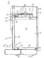
- FIGS 1 to 5 show a baler 1 with a new ejector 2.
- the baler 1 consists of a press housing 3, with a bottom surface 7, a rear wall 5, a front door 6-s. 6 to 9 with an integrated filling flap, not shown, and side walls 4, and surrounded by the press housing 3 shaft 34, arranged with at least one pressing region 8 and an overlying filling area 9, and one above the latter 9, here in the figures 1 to 2a, not shown, per se known drive for the baler, which is connected to a movable plate 34 in the press plate 15.
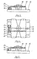
- the new ejector 2 consists of a lifting plate 10 which is rotatably mounted on the bottom surface 7 in the pressing region 8 of the shaft 34 by means of a bearing 11, a pull rod 12 with slider 12 a, which is preferably longitudinal - vertically - in the rear wall 5, with the lifting plate 10 is hingedly connected by a hinge 14 and in the upper end region has a specially angled, projecting into the pressing portion 8 end 24, and arranged from a arranged on the pressing plate entrainment of the temporary parts in the effective range of the end 24 of the drawbar 12 einschwenkbar are.
- a driver which consists of a pawl 16 and a driving hook 17 and is pivoted to a basic position so that a movement of the pressing plate 15 can take place; the catch hook 17 is formed in particular L-shaped.
- the pivoting of the driving hook 17 in the ejection position takes place when the front door 6 is open by the movement of a guided slide 18 via a handle element 19, while the slider 18 actuates the pawl 16.
- the pawl 16 and the catch hook 17 are mounted on a shaft 20 which is mounted in bearing blocks 21 and 22 which are mounted on the press plate 15.
- the slider 18 can manually through Operation of the handle member 19 in the direction of the rear wall 5 of the baler 1 are moved.
- the pawl 16 and the driving hook 17 are pivoted into a working position. If the pressure plate 15 now moves upward, the pull rod 12 is moved upwards via the driver hook 17, which engages in an angled end 24 of the pull rod 12, and the lifting plate 10 is pivoted upwards about the bearing 11 via the hinge 14.
- the material bale shown in part is ejected out of the pressing area 8 of the shaft 34 outwards in front of the baler by the front door 6, which is opened by approximately 180 degrees.
- the driving hook 17 strikes with its lower edge to the projecting into the pressing portion end 24 of the tie rod 12 and at the same time pivoted together with its pawl 16 in the said starting position automatically back ,
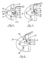
- the front door 6 is locked during the pressing operation by a closure device on one of the side walls of the press housing 3 while it is connected via hinges 6 with the other side wall.
- FIGS. 6 to 9 show details of the closure device, a latch 25 which is mounted on the press housing 3 and has a recess 26 in which a bolt 27 arranged on the front door 6 engages.
- a latch 25 which is mounted on the press housing 3 and has a recess 26 in which a bolt 27 arranged on the front door 6 engages.
- the bolt 27 By pivoting the bolt 25 upwards to a bearing 28 by means of movement of a handle 30, the bolt 27 snaps out of the recess 26 of the bolt 25 and the front door 6 can open according to Figure 7 by a defined angle range by the bolt 27th along a leading edge 29a of an opening beginning below the slot-like guide 29 moves until it abuts a guide 29 delimiting nose 31 of the bolt 25.
- the latch 25 has an outer projection 37 which abuts on further lifting of the bolt 25 in this phase of the opening operation to a above the locking pin 27 arranged securing pin 36 and an unintentional, fast opening - popping of the bolt 25 by the still pressurized front door 6 - prevented.
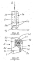
- the pressure plate 40 provided there is provided at its rear side, that is to say the rear wall 5 of the press housing 3, with at least one projecting U-shaped web 41. At the end, the two legs of the U-shaped web 41 are closed by a bolt 42, so that an enclosed gap 43 is formed, in which the binder for setting the finished pressed bale, usually band, is performed.
- the web 41 moves in a groove 5b provided in or on the rear wall 5, this groove 5b being formed by mutually spaced, angled limbs 5a 'of profile parts 5a of the rear wall 5.
- the inside width of this groove 5b is carried out as already described above.
- the feeding of the strip takes place in particular via a tube 33, the lower portion 33 a is directed so that the tape when inserted and pushed through the tube 33 is inevitably inserted into the gap 43 of the web 41.
- the tube 33 can be fastened either to the rear wall 5 of the press housing 3, or to the supporting structure of the drive unit, not shown above the filling area 9, or to the press plate 40 itself.
- the supply of the binder, not shown, to the tube 33 is carried out in a known manner, either from arranged on the back of the press housing or arranged in the front, upper region of the press supply rollers.
- the equipment of the baler with one or more control units together with safety circuits or devices, binder storage, binder tensioning device and the like units does not relate to the subject invention and were therefore not further described.
- This equipment of the baler is at the discretion of the operator or manufacturer of the baler.
Landscapes
- Engineering & Computer Science (AREA)
- Mechanical Engineering (AREA)
- Auxiliary Devices For And Details Of Packaging Control (AREA)
- Refuse Collection And Transfer (AREA)
- Preliminary Treatment Of Fibers (AREA)
- Press Drives And Press Lines (AREA)
- Basic Packing Technique (AREA)
- Separation By Low-Temperature Treatments (AREA)
Claims (6)
- Presse à balles pour compacter - compresser - notamment des matériaux d'emballage usagés ou encore des récipients de transport et/ou de stockage usagés, comme des cartonnages, des films plastiques, des bouteilles en PET ou autres objets et matériaux analogues, comprenant au moins :- un carter de presse (3), avec au moins une porte avant (6) ainsi qu'au moins un dispositif de fermeture pour cette porte (6),- une cellule (34) formée par le carter de presse (3) et dans laquelle est prévu un plateau de pressage mobile (15 ; 40),- un dispositif éjecteur (2) pour les balles pressées, associé au carter de presse (3), dispositif qui prévoit une bielle (12) guidée pour l'essentiel dans une paroi arrière (5) du carter de presse (3) et reliée en articulation à un plateau de levage (10) monté côté fond (7) dans la cellule (34), ainsi qu'un dispositif entraîneur pour une liaison temporaire de la bielle (12) avec le plateau de pressage (15 ; 40) de préférence verticalement mobile, et une unité d'entraînement qui est reliée au moins au plateau de pressage (15 ; 40) disposé dans la cellule (34),caractérisée en ce que le dispositif entraîneur est réalisé sous forme d'entraîneur mobile en pivotement pouvant être temporairement accouplé à la bielle (12), constitué d'un arbre (20) monté dans des blocs de palier (21, 22) et sur lequel un cliquet (16) et un crochet entraîneur (17) sont disposés de telle sorte,
et les blocs de palier (21, 22) de l'entraîneur conjointement avec l'arbre (20), le cliquet (16) et le crochet entraîneur (17) sont positionnés sur le plateau de pressage (15 ; 40) de telle sorte,
que, notamment lorsque la porte avant (6) est fermée, au moins le crochet entraîneur (17) et de préférence également le cliquet (16) prennent une position de base orientée vers l'intérieur, dirigée en éloignement de la paroi arrière (5),
et que, lorsque la porte avant (6) est ouverte, au moins temporairement pour la phase d'éjection de la balle, ils prennent une position d'éjection orientée vers l'extérieur, dirigée vers la paroi arrière (5),
sachant que, dans cette position d'éjection, pendant le mouvement ascendant du plateau de pressage (15 ; 40), il existe au moins temporairement une liaison du crochet entraîneur (17) avec la bielle (12). - Presse à balles selon la revendication 1, caractérisée en ce qu'il est prévu dans la région supérieure de la bielle (12) un coulisseau (12a) se trouvant à l'extérieur de la paroi arrière (5) et fixement disposé sur la bielle (12), ainsi que, dans la région de déplacement du coulisseau (12a), un guide (13) sur ou encore dans la paroi arrière (5), guide (13) qui s'étend au moins pour partie à l'extérieur sur la paroi arrière (5) et présente une épaisseur cunéiforme augmentant considéré en direction ascendante, sachant que la surface - bord - entrant en contact avec le coulisseau (12a) s'éloigne de manière croissante par rapport à la paroi arrière (5).
- Presse à balles selon la revendication 1 ou 2, caractérisée en ce que le crochet entraîneur (17) peut être actionné par le cliquet (16).
- Presse à balles selon l'une des revendications 1 à 3, caractérisée en ce que le crochet entraîneur (17) est notamment prévu sous la forme d'un crochet réalisé en L.
- Presse à balles selon l'une des revendications 1 à 4, caractérisée en ce qu'un poussoir (18) guidé, de préférence en forme de barre, est prévu sur le plateau de pressage (15), avec un élément de préhension (19) à l'une de ses extrémités et un élément de commutation (23) à son autre extrémité, l'élément de commutation (23) agissant lors de l'actionnement sur le cliquet (16).
- Presse à balles selon l'une des revendications 1 à 5, caractérisée en ce que le poussoir (18) peut être actionné de façon automatique.
Priority Applications (1)
| Application Number | Priority Date | Filing Date | Title |
|---|---|---|---|
| EP07008174A EP1808288A3 (fr) | 2000-06-26 | 2001-06-26 | Presse à balles |
Applications Claiming Priority (2)
| Application Number | Priority Date | Filing Date | Title |
|---|---|---|---|
| DE10029979 | 2000-06-26 | ||
| DE10029979A DE10029979C2 (de) | 2000-06-26 | 2000-06-26 | Ballenpresse |
Related Child Applications (1)
| Application Number | Title | Priority Date | Filing Date |
|---|---|---|---|
| EP07008174A Division EP1808288A3 (fr) | 2000-06-26 | 2001-06-26 | Presse à balles |
Publications (3)
| Publication Number | Publication Date |
|---|---|
| EP1167005A2 EP1167005A2 (fr) | 2002-01-02 |
| EP1167005A3 EP1167005A3 (fr) | 2003-07-23 |
| EP1167005B1 true EP1167005B1 (fr) | 2007-08-01 |
Family
ID=7646157
Family Applications (2)
| Application Number | Title | Priority Date | Filing Date |
|---|---|---|---|
| EP07008174A Withdrawn EP1808288A3 (fr) | 2000-06-26 | 2001-06-26 | Presse à balles |
| EP01115369A Expired - Lifetime EP1167005B1 (fr) | 2000-06-26 | 2001-06-26 | Presse à balles |
Family Applications Before (1)
| Application Number | Title | Priority Date | Filing Date |
|---|---|---|---|
| EP07008174A Withdrawn EP1808288A3 (fr) | 2000-06-26 | 2001-06-26 | Presse à balles |
Country Status (4)
| Country | Link |
|---|---|
| EP (2) | EP1808288A3 (fr) |
| JP (1) | JP2002059296A (fr) |
| AT (1) | ATE368565T1 (fr) |
| DE (2) | DE10029979C2 (fr) |
Family Cites Families (16)
| Publication number | Priority date | Publication date | Assignee | Title |
|---|---|---|---|---|
| DE1165451B (de) * | 1961-03-22 | 1964-03-12 | Wilmot Breeden Ltd | Hauben- oder Deckelverschluss insbesondere fuer Kraftfahrzeuge |
| US3916781A (en) * | 1973-02-16 | 1975-11-04 | American Environmental Prod | Bale ejection system |
| US3910181A (en) * | 1974-01-04 | 1975-10-07 | Fremco Manufacturing Inc | Baling press |
| DE2630906A1 (de) * | 1976-07-09 | 1978-01-12 | Schleicher Co Feinwerktech | Pressvorrichtung |
| US4232599A (en) * | 1978-10-19 | 1980-11-11 | J. V. Manufacturing & Welding, Inc. | Waste paper compacter with front access features |
| GB2060480B (en) * | 1979-10-18 | 1983-06-22 | Schleicher Co Feinwerktech | Baling press |
| DE3606309A1 (de) * | 1986-02-27 | 1987-09-03 | Hermann Schwelling | Fanghaken fuer den bedienungshebel des frontseitigen tuerverschlusses an horizontal wirkenden ballenpressen |
| DE3907334A1 (de) * | 1989-03-08 | 1990-09-20 | Schleicher Co Feinwerktech | Verschlussvorrichtung fuer die tuer einer ballenpresse |
| US5062358A (en) * | 1989-09-11 | 1991-11-05 | Marcella M. Fox | Bale ejector for a trash compactor |
| DE4215639C2 (de) * | 1992-03-07 | 1996-05-02 | Bermatingen Maschf | Vorrichtung zur Arretierung einer Auswurfklappe für den Preßkasten einer Ballenpresse |
| DE4336437A1 (de) * | 1993-10-26 | 1995-04-27 | Bermatingen Maschf | Ballenpresse |
| ES2134990T3 (es) * | 1994-12-27 | 1999-10-16 | Hermann Schwelling | Puerta frontal de seguridad para prensa embaladora. |
| US5575199A (en) * | 1995-03-22 | 1996-11-19 | Yamamoto; Soichiro | Compactor |
| DE19738060A1 (de) * | 1997-09-01 | 1999-03-11 | Hermann Schwelling | Abfallpresse mit Auswurfeinrichtung für Ballen |
| DE29721834U1 (de) * | 1997-12-10 | 1998-04-09 | Schwelling, Hermann, 88682 Salem | Sicherheitsverschluß für die Preßschachttür von Abfall-Ballenpressen |
| DE19817807B4 (de) * | 1998-04-21 | 2012-06-28 | Hermann Schwelling | Schachttür für eine Ballenpresse und zugehörige Ballenpresse |
-
2000
- 2000-06-26 DE DE10029979A patent/DE10029979C2/de not_active Expired - Fee Related
-
2001
- 2001-06-26 AT AT01115369T patent/ATE368565T1/de not_active IP Right Cessation
- 2001-06-26 EP EP07008174A patent/EP1808288A3/fr not_active Withdrawn
- 2001-06-26 JP JP2001192758A patent/JP2002059296A/ja active Pending
- 2001-06-26 EP EP01115369A patent/EP1167005B1/fr not_active Expired - Lifetime
- 2001-06-26 DE DE50112780T patent/DE50112780D1/de not_active Expired - Fee Related
Also Published As
| Publication number | Publication date |
|---|---|
| DE10029979A1 (de) | 2002-01-17 |
| EP1808288A2 (fr) | 2007-07-18 |
| DE50112780D1 (de) | 2007-09-13 |
| EP1808288A3 (fr) | 2008-01-23 |
| ATE368565T1 (de) | 2007-08-15 |
| DE10029979C2 (de) | 2003-11-06 |
| EP1167005A2 (fr) | 2002-01-02 |
| EP1167005A3 (fr) | 2003-07-23 |
| JP2002059296A (ja) | 2002-02-26 |
Similar Documents
| Publication | Publication Date | Title |
|---|---|---|
| DE2126780C3 (de) | Mullfahrzeug mit hinter dem Sammelbehalter gelegenem Einfullraum und einem trogförmigen Vorverdichtungs raum | |
| DE2330157A1 (de) | Vorrichtung zum verdichten bzw. pressen von material wie abfall u.dgl | |
| EP2283999B1 (fr) | Presse à ballot | |
| DE2411744A1 (de) | Presse zum pressverbinden eines mindestens teilweise drahtfoermigen teiles mit einem abschlussteil | |
| DE10251516B4 (de) | Ballenpresse | |
| DE69505627T2 (de) | Drehbare Vorrichtung zum Freisetzen des Balles in Ballenpressen und Verfahren zum Verpressen zu Ballen | |
| EP1167005B1 (fr) | Presse à balles | |
| EP3017939A1 (fr) | Presse a empaqueter | |
| EP0899088B1 (fr) | Compacteur de déchets ayant un dispositif d'éjection de balles | |
| EP3453529B1 (fr) | Presse à coffre à balles pourvue de porte coulissante ainsi que procédé de fonctionnement d'une presse à coffre | |
| DE29919933U1 (de) | Vorrichtung zum Zusammenpressen von Abfall | |
| DE19738060A1 (de) | Abfallpresse mit Auswurfeinrichtung für Ballen | |
| DE1274963B (de) | Muellfahrzeug | |
| DE3412307A1 (de) | Ballenpresse zum zusammenpressen von materialien wie papierabfaellen o. dgl. zu ballen | |
| DE69404057T2 (de) | Verdichter | |
| EP1171283B1 (fr) | Presse a mettre en balles, pourvue d'une caisse de presse qui peut etre basculee, et procede pour actionner ladite presse | |
| DE2917118C2 (fr) | ||
| DE4114893A1 (de) | Holzspaltvorrichtung mit hydraulisch betaetigbarem stempel | |
| DE20010786U1 (de) | Ballenpresse | |
| DE9004989U1 (de) | Ballenpresse | |
| DE10029440A1 (de) | Presse | |
| DE3238542A1 (de) | Vorrichtung zum fuehren und ziehen der abbindestreifen bei ballenpressen vertikaler bauart fuer abfallmaterialien | |
| DE4336437A1 (de) | Ballenpresse | |
| DE29904482U1 (de) | Schiebetür mit Klappe an einer Ballenpresse | |
| DE9218398U1 (de) | Verschlußvorrichtung |
Legal Events
| Date | Code | Title | Description |
|---|---|---|---|
| PUAI | Public reference made under article 153(3) epc to a published international application that has entered the european phase |
Free format text: ORIGINAL CODE: 0009012 |
|
| AK | Designated contracting states |
Kind code of ref document: A2 Designated state(s): AT BE CH CY DE DK ES FI FR GB GR IE IT LI LU MC NL PT SE TR |
|
| AX | Request for extension of the european patent |
Free format text: AL;LT;LV;MK;RO;SI |
|
| PUAL | Search report despatched |
Free format text: ORIGINAL CODE: 0009013 |
|
| AK | Designated contracting states |
Designated state(s): AT BE CH CY DE DK ES FI FR GB GR IE IT LI LU MC NL PT SE TR |
|
| AX | Request for extension of the european patent |
Extension state: AL LT LV MK RO SI |
|
| 17P | Request for examination filed |
Effective date: 20040122 |
|
| AKX | Designation fees paid |
Designated state(s): AT DE ES FR GB SE |
|
| GRAP | Despatch of communication of intention to grant a patent |
Free format text: ORIGINAL CODE: EPIDOSNIGR1 |
|
| GRAS | Grant fee paid |
Free format text: ORIGINAL CODE: EPIDOSNIGR3 |
|
| GRAA | (expected) grant |
Free format text: ORIGINAL CODE: 0009210 |
|
| AK | Designated contracting states |
Kind code of ref document: B1 Designated state(s): AT DE ES FR GB SE |
|
| REG | Reference to a national code |
Ref country code: GB Ref legal event code: FG4D Free format text: NOT ENGLISH |
|
| REF | Corresponds to: |
Ref document number: 50112780 Country of ref document: DE Date of ref document: 20070913 Kind code of ref document: P |
|
| REG | Reference to a national code |
Ref country code: SE Ref legal event code: TRGR |
|
| ET | Fr: translation filed | ||
| PG25 | Lapsed in a contracting state [announced via postgrant information from national office to epo] |
Ref country code: ES Free format text: LAPSE BECAUSE OF FAILURE TO SUBMIT A TRANSLATION OF THE DESCRIPTION OR TO PAY THE FEE WITHIN THE PRESCRIBED TIME-LIMIT Effective date: 20071112 |
|
| GBV | Gb: ep patent (uk) treated as always having been void in accordance with gb section 77(7)/1977 [no translation filed] |
Effective date: 20070801 |
|
| PG25 | Lapsed in a contracting state [announced via postgrant information from national office to epo] |
Ref country code: GB Free format text: LAPSE BECAUSE OF FAILURE TO SUBMIT A TRANSLATION OF THE DESCRIPTION OR TO PAY THE FEE WITHIN THE PRESCRIBED TIME-LIMIT Effective date: 20070801 |
|
| PLBE | No opposition filed within time limit |
Free format text: ORIGINAL CODE: 0009261 |
|
| STAA | Information on the status of an ep patent application or granted ep patent |
Free format text: STATUS: NO OPPOSITION FILED WITHIN TIME LIMIT |
|
| 26N | No opposition filed |
Effective date: 20080506 |
|
| PG25 | Lapsed in a contracting state [announced via postgrant information from national office to epo] |
Ref country code: DE Free format text: LAPSE BECAUSE OF NON-PAYMENT OF DUE FEES Effective date: 20090101 |
|
| PG25 | Lapsed in a contracting state [announced via postgrant information from national office to epo] |
Ref country code: AT Free format text: LAPSE BECAUSE OF NON-PAYMENT OF DUE FEES Effective date: 20080626 |
|
| PGFP | Annual fee paid to national office [announced via postgrant information from national office to epo] |
Ref country code: FR Payment date: 20100716 Year of fee payment: 10 |
|
| REG | Reference to a national code |
Ref country code: FR Ref legal event code: ST Effective date: 20120229 |
|
| PG25 | Lapsed in a contracting state [announced via postgrant information from national office to epo] |
Ref country code: FR Free format text: LAPSE BECAUSE OF NON-PAYMENT OF DUE FEES Effective date: 20110630 |
|
| PGFP | Annual fee paid to national office [announced via postgrant information from national office to epo] |
Ref country code: SE Payment date: 20130624 Year of fee payment: 13 |
|
| PG25 | Lapsed in a contracting state [announced via postgrant information from national office to epo] |
Ref country code: SE Free format text: LAPSE BECAUSE OF NON-PAYMENT OF DUE FEES Effective date: 20140627 |
|
| REG | Reference to a national code |
Ref country code: SE Ref legal event code: EUG |