EP0899180A2 - Dispositif pour contrÔler un vérin hydraulique de direction à double effet - Google Patents
Dispositif pour contrÔler un vérin hydraulique de direction à double effet Download PDFInfo
- Publication number
- EP0899180A2 EP0899180A2 EP98111524A EP98111524A EP0899180A2 EP 0899180 A2 EP0899180 A2 EP 0899180A2 EP 98111524 A EP98111524 A EP 98111524A EP 98111524 A EP98111524 A EP 98111524A EP 0899180 A2 EP0899180 A2 EP 0899180A2
- Authority
- EP
- European Patent Office
- Prior art keywords
- valve
- switching
- valves
- steering cylinder
- steering
- Prior art date
- Legal status (The legal status is an assumption and is not a legal conclusion. Google has not performed a legal analysis and makes no representation as to the accuracy of the status listed.)
- Withdrawn
Links
- 239000012530 fluid Substances 0.000 claims abstract description 7
- 230000005284 excitation Effects 0.000 claims description 2
- 238000010586 diagram Methods 0.000 description 2
- 238000012423 maintenance Methods 0.000 description 2
- 230000006978 adaptation Effects 0.000 description 1
- 230000000903 blocking effect Effects 0.000 description 1
- 230000001419 dependent effect Effects 0.000 description 1
- 230000006870 function Effects 0.000 description 1
- 238000003306 harvesting Methods 0.000 description 1
- 230000004044 response Effects 0.000 description 1
- 238000004904 shortening Methods 0.000 description 1
Images
Classifications
-
- F—MECHANICAL ENGINEERING; LIGHTING; HEATING; WEAPONS; BLASTING
- F15—FLUID-PRESSURE ACTUATORS; HYDRAULICS OR PNEUMATICS IN GENERAL
- F15B—SYSTEMS ACTING BY MEANS OF FLUIDS IN GENERAL; FLUID-PRESSURE ACTUATORS, e.g. SERVOMOTORS; DETAILS OF FLUID-PRESSURE SYSTEMS, NOT OTHERWISE PROVIDED FOR
- F15B11/00—Servomotor systems without provision for follow-up action; Circuits therefor
- F15B11/003—Systems with load-holding valves
-
- A—HUMAN NECESSITIES
- A01—AGRICULTURE; FORESTRY; ANIMAL HUSBANDRY; HUNTING; TRAPPING; FISHING
- A01B—SOIL WORKING IN AGRICULTURE OR FORESTRY; PARTS, DETAILS, OR ACCESSORIES OF AGRICULTURAL MACHINES OR IMPLEMENTS, IN GENERAL
- A01B69/00—Steering of agricultural machines or implements; Guiding agricultural machines or implements on a desired track
- A01B69/007—Steering or guiding of agricultural vehicles, e.g. steering of the tractor to keep the plough in the furrow
-
- B—PERFORMING OPERATIONS; TRANSPORTING
- B62—LAND VEHICLES FOR TRAVELLING OTHERWISE THAN ON RAILS
- B62D—MOTOR VEHICLES; TRAILERS
- B62D5/00—Power-assisted or power-driven steering
- B62D5/06—Power-assisted or power-driven steering fluid, i.e. using a pressurised fluid for most or all the force required for steering a vehicle
-
- F—MECHANICAL ENGINEERING; LIGHTING; HEATING; WEAPONS; BLASTING
- F15—FLUID-PRESSURE ACTUATORS; HYDRAULICS OR PNEUMATICS IN GENERAL
- F15B—SYSTEMS ACTING BY MEANS OF FLUIDS IN GENERAL; FLUID-PRESSURE ACTUATORS, e.g. SERVOMOTORS; DETAILS OF FLUID-PRESSURE SYSTEMS, NOT OTHERWISE PROVIDED FOR
- F15B2211/00—Circuits for servomotor systems
- F15B2211/30—Directional control
- F15B2211/305—Directional control characterised by the type of valves
- F15B2211/30505—Non-return valves, i.e. check valves
- F15B2211/3051—Cross-check valves
-
- F—MECHANICAL ENGINEERING; LIGHTING; HEATING; WEAPONS; BLASTING
- F15—FLUID-PRESSURE ACTUATORS; HYDRAULICS OR PNEUMATICS IN GENERAL
- F15B—SYSTEMS ACTING BY MEANS OF FLUIDS IN GENERAL; FLUID-PRESSURE ACTUATORS, e.g. SERVOMOTORS; DETAILS OF FLUID-PRESSURE SYSTEMS, NOT OTHERWISE PROVIDED FOR
- F15B2211/00—Circuits for servomotor systems
- F15B2211/30—Directional control
- F15B2211/305—Directional control characterised by the type of valves
- F15B2211/3056—Assemblies of multiple valves
- F15B2211/30565—Assemblies of multiple valves having multiple valves for a single output member, e.g. for creating higher valve function by use of multiple valves like two 2/2-valves replacing a 5/3-valve
- F15B2211/3057—Assemblies of multiple valves having multiple valves for a single output member, e.g. for creating higher valve function by use of multiple valves like two 2/2-valves replacing a 5/3-valve having two valves, one for each port of a double-acting output member
-
- F—MECHANICAL ENGINEERING; LIGHTING; HEATING; WEAPONS; BLASTING
- F15—FLUID-PRESSURE ACTUATORS; HYDRAULICS OR PNEUMATICS IN GENERAL
- F15B—SYSTEMS ACTING BY MEANS OF FLUIDS IN GENERAL; FLUID-PRESSURE ACTUATORS, e.g. SERVOMOTORS; DETAILS OF FLUID-PRESSURE SYSTEMS, NOT OTHERWISE PROVIDED FOR
- F15B2211/00—Circuits for servomotor systems
- F15B2211/30—Directional control
- F15B2211/315—Directional control characterised by the connections of the valve or valves in the circuit
- F15B2211/3157—Directional control characterised by the connections of the valve or valves in the circuit being connected to a pressure source, an output member and a return line
- F15B2211/31576—Directional control characterised by the connections of the valve or valves in the circuit being connected to a pressure source, an output member and a return line having a single pressure source and a single output member
-
- F—MECHANICAL ENGINEERING; LIGHTING; HEATING; WEAPONS; BLASTING
- F15—FLUID-PRESSURE ACTUATORS; HYDRAULICS OR PNEUMATICS IN GENERAL
- F15B—SYSTEMS ACTING BY MEANS OF FLUIDS IN GENERAL; FLUID-PRESSURE ACTUATORS, e.g. SERVOMOTORS; DETAILS OF FLUID-PRESSURE SYSTEMS, NOT OTHERWISE PROVIDED FOR
- F15B2211/00—Circuits for servomotor systems
- F15B2211/30—Directional control
- F15B2211/32—Directional control characterised by the type of actuation
- F15B2211/327—Directional control characterised by the type of actuation electrically or electronically
-
- F—MECHANICAL ENGINEERING; LIGHTING; HEATING; WEAPONS; BLASTING
- F15—FLUID-PRESSURE ACTUATORS; HYDRAULICS OR PNEUMATICS IN GENERAL
- F15B—SYSTEMS ACTING BY MEANS OF FLUIDS IN GENERAL; FLUID-PRESSURE ACTUATORS, e.g. SERVOMOTORS; DETAILS OF FLUID-PRESSURE SYSTEMS, NOT OTHERWISE PROVIDED FOR
- F15B2211/00—Circuits for servomotor systems
- F15B2211/40—Flow control
- F15B2211/45—Control of bleed-off flow, e.g. control of bypass flow to the return line
-
- F—MECHANICAL ENGINEERING; LIGHTING; HEATING; WEAPONS; BLASTING
- F15—FLUID-PRESSURE ACTUATORS; HYDRAULICS OR PNEUMATICS IN GENERAL
- F15B—SYSTEMS ACTING BY MEANS OF FLUIDS IN GENERAL; FLUID-PRESSURE ACTUATORS, e.g. SERVOMOTORS; DETAILS OF FLUID-PRESSURE SYSTEMS, NOT OTHERWISE PROVIDED FOR
- F15B2211/00—Circuits for servomotor systems
- F15B2211/60—Circuit components or control therefor
- F15B2211/625—Accumulators
Definitions
- the invention relates to a device for controlling a double acting steering cylinder of vehicle steering systems, in particular of agricultural vehicle steering, with two working connections of the steering cylinder, the working connections in each case by means of an inlet line or a drain line are connected to a valve unit.
- the invention is characterized in that that the valve unit has two switching valves, alternately in a first switching position and can be brought into a second switching position, wherein the steering cylinder in the first shift position of the first Switch valve with a fluid at the first working connection and in the second switching position of the second switching valve supplied with the fluid at the second working connection is and vice versa.
- the particular advantage of the invention is that the Valve unit faster switching of the steering cylinder enables.
- the fact that the switching valves only two can take defined switching positions can by Combination of the two switching valves a quick reversal of direction of the piston located in the steering cylinder be achieved.
- the circuit design to control the switching valves reduced, because each Switching valve can only be brought into two switching positions is.
- the switching valves each from a 3/2-way valve, the are integrated in a valve unit.
- the 3/2-way valves are of the same design.
- the switching valves independently actuated electromagnetically, the electromagnet with an electrical control signal is applied.
- the electromagnet has a pre-excitation such that the switching valve just in the second switching position blocked the pressure connection of the same. In this position the solenoid already acts on the switching valve without to open it however.
- To move the switching valve in its first switch position is enough to increase the force slightly of the electromagnet, so that the result is a quick switching of the switching valve from the second to the first switching position and vice versa is made possible.
- the switching valves each designed as a slide seat valve, wherein in the second switching position of the switching valve is spring-loaded Ball is arranged in a valve seat.
- This ball can be moved by means of a valve lifter the valve quickly into a first opening the pressure port Switch position are brought.
- Through the ball seat advantageously allows the reservoir to be leak-free.
- valve lifter is connected in one piece to a slide, which is circumferential in this way the valve lifter is arranged that when actuated of the switching valve the inlet and outlet line of the switching valve are temporarily blocked.
- the device according to the invention becomes self-steering an agricultural vehicle, for example one Combine or a chopper used.
- a steering cylinder depending on a predetermined setpoint a steering so acted that even if it occurs of disturbances of the pistons in the steering cylinder such Position assumes that the vehicle is heading in the desired direction maintains.
- the control of those described below Valves are made using a control device that generates a control signal depending on the given Target position, the current actual position of the vehicle as well if necessary, depending on disturbance variables acting on the system.
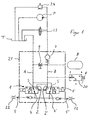
- FIG. 1 shows a block diagram of the invention Device in which two switching valves 1 and 1 'are provided are that can be controlled independently of each other.
- the Switching valves 1, 1 'are each designed as 3/2-way valves, each electromagnetic via a control signal are operable.
- a control unit not shown, delivers the control signals such that the switching valves 1, 1 ' each in a first switching position and in a second Switch position can be brought.
- the pressure connections 2, 2 'of the switching valves 1, 1' are each via a common feed line Z on the one hand a check valve 7 with a pump P and the other connected to a memory 8.
- a maintenance valve 9 is arranged, that is in the locked position when the steering is in operation and is only opened for maintenance purposes, so that the Memory 8 can be emptied.
- a piston 10 of the steering cylinder 6 to a certain Moving in a given direction for example the switching valve 1, which is connected to the working connection 5 of the steering cylinder 6 corresponds, by an actuating signal acted upon and brought into a first switching position.
- the Pressure port 2 is now via the inlet line Z with connected to the memory or the pump P and the working connection 4 is connected to the working connection 5 of the cylinder 6.
- the return connection 3 is blocked.
- the hydraulic fluid can now from the memory 8 or the pump P via the Switch valve 1 to the working connection 5 of the cylinder 6 flow.
- the hydraulic fluid flows through the working connection 5 ' depressurized from the steering cylinder 6 to the working connection 4 'of that in a second switching position Switching valve 1 'and from this via the return connection 3 'to the tank T.
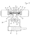
- the switching valves 1, 1 ' formed uniformly and arranged coaxially to each other.
- the switching valves 1, 1 ' are as slide seat switching valves formed, with a ball 11, 11 'on a Valve seat 12, 12 'pressed by means of a spring 13, 13' becomes.
- a valve tappet 14, 14 ' By actuating a valve tappet 14, 14 'by means of an electromagnet 15, 15 'is the ball 11, 11' the valve seat 12, 12 'pressed so that the switching valve 1, 1 'is now in the first switching position.
- the valve tappet moves 14 a slide 16, 16 'connected in one piece to this moves with the slider 16, 16 'before lifting the ball 11, 11 'from the valve seat 12, 12' the drain line A blocks.
- the switching valves 1, 1 'as ball seat valves is a quick response of the valves and thus enables a quick switchover.
- the Storage 8 via the pressure connection 2, 2 'of the valves 1, 1' Sealed without leak oil.
- the diameter of the valve seat 12, 12 ' is dimensioned so small that with sufficient Volume flow is a comparatively low force for switching of the valve 1, 1 'is required.
- Another Shortening the switching time is achieved in that the Electromagnet 15, 15 'is pre-excited, that is, with an electric current that is so large that in the second switching position of the valve 1, 1 'the ball 11, 11 'just not out of the valve seat 12, 12' is pushed out. When switching to the first switching position only a slight increase in force is now required, to push the ball 11, 11 'out of the valve seat 12, 12'.
- a valve unit 21 has a blocking block 17, which has two check valves 18, 18 'which are in operation open the lines of the device according to the invention and when the device is not operating, the feed lines are closed lock the steering cylinder 6 securely.
- This lock block 17 is required because the valve unit 21 is part of a separate working hydraulic circuit is that in self-steering mode from one for the normal operation of the steering provided steering hydraulic circuit is separated.
- the separate one Working hydraulic circuit is also used to control other functions, for example for cutting unit lifting etc. So that in the operating position of the valve unit 21 the opening of the two leading to the steering cylinder 6 Lines is guaranteed, that of the unpressurized line assigned check valve 18, 18 'by means of a Piston 19 brought into the open position.
- the control of the piston 19 is carried out by the pressurized Working connection 4, 4 'of the corresponding switching valve 1, 1'.
- An electrical pressure switch 20 is operatively connected with a 2/2 way valve 23, so that when falling below a Minimum pressure of the memory 8 this replenished can be. After switching off the directional valve 23, the Storage pressure held by the check valve 7. A Pressure relief valve 24 protects the hydraulic circuit of overload.
- the switching valves 1, 1 ' designed as twin valves that are directly adjacent to each other and have a common feed line Z.
- the valve unit 21 with respect to a central axis is constructed symmetrically for the switching valves 1, 1 'the same components are used.
- the valve unit 21 enables one fast switching of the valves, especially small ones Steering angle can be quickly compensated in this way. In particular, this results in a rear wheel steering reduces the risk of oversteer. As a result, a higher speed or a higher performance of the Vehicle are achieved so that the harvesting performance increases.
Landscapes
- Engineering & Computer Science (AREA)
- Mechanical Engineering (AREA)
- Life Sciences & Earth Sciences (AREA)
- Fluid Mechanics (AREA)
- Transportation (AREA)
- Physics & Mathematics (AREA)
- Chemical & Material Sciences (AREA)
- General Engineering & Computer Science (AREA)
- Combustion & Propulsion (AREA)
- Soil Sciences (AREA)
- Environmental Sciences (AREA)
- Fluid-Pressure Circuits (AREA)
- Guiding Agricultural Machines (AREA)
Applications Claiming Priority (2)
| Application Number | Priority Date | Filing Date | Title |
|---|---|---|---|
| DE19737005A DE19737005A1 (de) | 1997-08-26 | 1997-08-26 | Vorrichtung zur Steuerung eines doppelt wirkenden Lenkzylinders |
| DE19737005 | 1997-08-26 |
Publications (2)
| Publication Number | Publication Date |
|---|---|
| EP0899180A2 true EP0899180A2 (fr) | 1999-03-03 |
| EP0899180A3 EP0899180A3 (fr) | 2001-01-10 |
Family
ID=7840132
Family Applications (1)
| Application Number | Title | Priority Date | Filing Date |
|---|---|---|---|
| EP98111524A Withdrawn EP0899180A3 (fr) | 1997-08-26 | 1998-06-23 | Dispositif pour contrôler un vérin hydraulique de direction à double effet |
Country Status (3)
| Country | Link |
|---|---|
| US (1) | US6047628A (fr) |
| EP (1) | EP0899180A3 (fr) |
| DE (1) | DE19737005A1 (fr) |
Cited By (1)
| Publication number | Priority date | Publication date | Assignee | Title |
|---|---|---|---|---|
| CN113447812A (zh) * | 2020-03-25 | 2021-09-28 | 宁波强生电机有限公司 | 一种直流电机测试装置 |
Families Citing this family (2)
| Publication number | Priority date | Publication date | Assignee | Title |
|---|---|---|---|---|
| EP0982503B1 (fr) * | 1998-08-24 | 2005-09-14 | Industria de Turbo Propulsores S.A. | Piston à servocommande avec détection hydromécanique autonome |
| US6871574B2 (en) * | 2003-05-28 | 2005-03-29 | Husco International, Inc. | Hydraulic control valve assembly having dual directional spool valves with pilot operated check valves |
Citations (1)
| Publication number | Priority date | Publication date | Assignee | Title |
|---|---|---|---|---|
| DE19539088A1 (de) | 1995-10-20 | 1997-04-24 | Claas Ohg | Selbstlenkvorrichtung mit Proportionalventil |
Family Cites Families (14)
| Publication number | Priority date | Publication date | Assignee | Title |
|---|---|---|---|---|
| FR2321416A1 (fr) * | 1975-08-21 | 1977-03-18 | Dba | Dispositif hydraulique d'assistance pour direction de vehicule automobile |
| US4227481A (en) * | 1978-10-13 | 1980-10-14 | Cox Burton B | Safety steering system for outboard motors |
| DE2900510A1 (de) * | 1979-01-08 | 1980-07-17 | Bosch Gmbh Robert | Servolenkung fuer kraftfahrzeuge |
| DE2935065C2 (de) * | 1979-08-30 | 1985-05-23 | Jungheinrich Unternehmensverwaltung Kg, 2000 Hamburg | Elektro-hydraulische Proportionalsteuerung zur Lenkung induktiv geführter Flurförderfahrzeuge |
| DE3331582A1 (de) * | 1983-09-01 | 1985-03-21 | Dr.Ing.H.C. F. Porsche Ag, 7000 Stuttgart | 4/3-wegeventil |
| DE3347000A1 (de) * | 1983-12-24 | 1985-07-04 | Robert Bosch Gmbh, 7000 Stuttgart | Elektrohydraulische einrichtung zur steuerung eines doppeltwirkenden hydromotors |
| DE3422024A1 (de) * | 1984-06-14 | 1985-12-19 | Thyssen Industrie Ag, 4300 Essen | Steuerventil, insbesondere fuer den hydraulischen schreitausbau |
| US4623031A (en) * | 1985-02-22 | 1986-11-18 | Trw Inc. | Control apparatus for a steering system |
| DE3621864A1 (de) * | 1986-06-30 | 1988-01-14 | Teves Gmbh Alfred | Einparklenkhilfevorrichtung |
| DE3729898A1 (de) * | 1987-09-07 | 1989-03-23 | Bosch Gmbh Robert | Hydraulischer stellantrieb |
| IT1238531B (it) * | 1989-11-10 | 1993-08-18 | Fiat Auto Spa | Servosterzo per autoveicoli |
| US5609400A (en) * | 1993-09-27 | 1997-03-11 | Sumitomo Electric Industries, Ltd. | Three position solenoid controlled valve |
| DE4340283A1 (de) * | 1993-11-26 | 1995-06-01 | Claas Ohg | Hydraulisches Steuerventil |
| DE19603270C1 (de) * | 1996-01-30 | 1997-07-10 | Daimler Benz Ag | Hydraulische Servolenkung für Kraftfahrzeuge |
-
1997
- 1997-08-26 DE DE19737005A patent/DE19737005A1/de not_active Withdrawn
-
1998
- 1998-06-23 EP EP98111524A patent/EP0899180A3/fr not_active Withdrawn
- 1998-08-25 US US09/139,827 patent/US6047628A/en not_active Expired - Fee Related
Patent Citations (1)
| Publication number | Priority date | Publication date | Assignee | Title |
|---|---|---|---|---|
| DE19539088A1 (de) | 1995-10-20 | 1997-04-24 | Claas Ohg | Selbstlenkvorrichtung mit Proportionalventil |
Cited By (2)
| Publication number | Priority date | Publication date | Assignee | Title |
|---|---|---|---|---|
| CN113447812A (zh) * | 2020-03-25 | 2021-09-28 | 宁波强生电机有限公司 | 一种直流电机测试装置 |
| CN113447812B (zh) * | 2020-03-25 | 2024-03-26 | 宁波强生电机有限公司 | 一种直流电机测试装置 |
Also Published As
| Publication number | Publication date |
|---|---|
| DE19737005A1 (de) | 1999-03-04 |
| US6047628A (en) | 2000-04-11 |
| EP0899180A3 (fr) | 2001-01-10 |
Similar Documents
| Publication | Publication Date | Title |
|---|---|---|
| DE3323363C2 (fr) | ||
| DE2446963C2 (de) | Hydraulische Stelleinrichtung | |
| DE2003115A1 (de) | Ventil fuer veraenderlichen Durchfluss | |
| DE19931142C2 (de) | Hydraulische Ventilanordnung mit Verriegelungsfunktion | |
| DE1921977B2 (de) | Ventileinrichtung zur Steuerung der Druckmittelwege eines doppelwirkenden Servomotors | |
| DE60304663T2 (de) | Hydraulische Ventileinrichtung | |
| EP0136457A2 (fr) | Soupape à 4/3-voies | |
| DE69222861T2 (de) | Hydraulische schaltung mit druckausgleichventil | |
| DE1179124B (de) | Vorrichtung zur Kurvenstabilisierung des Wagenkastens bei Kraftfahrzeugen | |
| DE3890121C2 (de) | Hydraulisches Schnellablaßventil und hydraulischer Fernsteuerungskreis mit einem solchen Schnellablaßventil | |
| DE4115594A1 (de) | Proportional-druckregelventil | |
| DE3813020C2 (de) | Vorrichtung zur Vorschubsteuerung einer hydraulischen Stelleinrichtung | |
| DE3015367A1 (de) | Hydrostatischer antrieb | |
| DE19829530A1 (de) | Ventilanordnung | |
| EP0182100A2 (fr) | Dispositif de commande hydraulique | |
| EP0899180A2 (fr) | Dispositif pour contrÔler un vérin hydraulique de direction à double effet | |
| DE60306847T2 (de) | Pflugwendevorrichtung | |
| DE3703019C2 (de) | Hydraulische Stellvorrichtung für ein zu bewegendes Teil eines Fluggeräts | |
| DE3519148C2 (fr) | ||
| DE3935756A1 (de) | Hydraulische anlage in einem kraftfahrzeug | |
| DE3905654C2 (de) | Hydraulische Steuervorrichtung | |
| DE4240076A1 (de) | Hydraulische Steuereinrichtung für einen Arbeitszylinder | |
| DE102016212306A1 (de) | Zwischenblock und Kompaktachse mit einem Zwischenblock | |
| DE2850291A1 (de) | Servobetaetigtes dreiwegeventil | |
| DE3606237A1 (de) | Doppelfahrbremsventil |
Legal Events
| Date | Code | Title | Description |
|---|---|---|---|
| PUAI | Public reference made under article 153(3) epc to a published international application that has entered the european phase |
Free format text: ORIGINAL CODE: 0009012 |
|
| AK | Designated contracting states |
Kind code of ref document: A2 Designated state(s): AT BE CH CY DE DK ES FI FR GB GR IE IT LI LU MC NL PT SE |
|
| AX | Request for extension of the european patent |
Free format text: AL;LT;LV;MK;RO;SI |
|
| PUAL | Search report despatched |
Free format text: ORIGINAL CODE: 0009013 |
|
| AK | Designated contracting states |
Kind code of ref document: A3 Designated state(s): AT BE CH CY DE DK ES FI FR GB GR IE IT LI LU MC NL PT SE |
|
| AX | Request for extension of the european patent |
Free format text: AL;LT;LV;MK;RO;SI |
|
| STAA | Information on the status of an ep patent application or granted ep patent |
Free format text: STATUS: THE APPLICATION HAS BEEN WITHDRAWN |
|
| 18W | Application withdrawn |
Withdrawal date: 20010120 |