EP0899191B1 - Flugzeugbugfahrwerk - Google Patents
Flugzeugbugfahrwerk Download PDFInfo
- Publication number
- EP0899191B1 EP0899191B1 EP98202425A EP98202425A EP0899191B1 EP 0899191 B1 EP0899191 B1 EP 0899191B1 EP 98202425 A EP98202425 A EP 98202425A EP 98202425 A EP98202425 A EP 98202425A EP 0899191 B1 EP0899191 B1 EP 0899191B1
- Authority
- EP
- European Patent Office
- Prior art keywords
- landing gear
- wheel well
- nose
- nose wheel
- outboard
- Prior art date
- Legal status (The legal status is an assumption and is not a legal conclusion. Google has not performed a legal analysis and makes no representation as to the accuracy of the status listed.)
- Expired - Lifetime
Links
- 230000035939 shock Effects 0.000 claims description 9
- 230000014759 maintenance of location Effects 0.000 claims description 6
- 238000009434 installation Methods 0.000 description 5
- 229910000831 Steel Inorganic materials 0.000 description 3
- 238000005461 lubrication Methods 0.000 description 3
- 239000010959 steel Substances 0.000 description 3
- 230000000712 assembly Effects 0.000 description 2
- 238000000429 assembly Methods 0.000 description 2
- 238000004519 manufacturing process Methods 0.000 description 2
- 238000000034 method Methods 0.000 description 2
- 230000001419 dependent effect Effects 0.000 description 1
- 239000000314 lubricant Substances 0.000 description 1
- 230000001050 lubricating effect Effects 0.000 description 1
- 230000005012 migration Effects 0.000 description 1
- 238000013508 migration Methods 0.000 description 1
Images



Classifications
-
- B—PERFORMING OPERATIONS; TRANSPORTING
- B64—AIRCRAFT; AVIATION; COSMONAUTICS
- B64C—AEROPLANES; HELICOPTERS
- B64C25/00—Alighting gear
-
- B—PERFORMING OPERATIONS; TRANSPORTING
- B64—AIRCRAFT; AVIATION; COSMONAUTICS
- B64C—AEROPLANES; HELICOPTERS
- B64C25/00—Alighting gear
- B64C25/02—Undercarriages
- B64C25/08—Undercarriages non-fixed, e.g. jettisonable
- B64C25/10—Undercarriages non-fixed, e.g. jettisonable retractable, foldable, or the like
Definitions
- the present invention relates to a nose gear installation and more particularly to a means for securing an aircraft nose landing gear assembly into the nose wheel well support structure of an aircraft. Specifically, the invention relates to an aircraft nose landing gear system as defined in the pre-characterizing part of claim 1.
- EP-A-0 597 688 discloses a trolley for transporting and positioning a landing gear prior to installation on an aircraft.
- a landing gear is positioned in the wheel well such as to align the fittings or bearings on the landing gear with corresponding bearings in the wheel well structure, after which a trunnion pin or pintle pin is inserted into the bearings. It is summarily stated that the bearings are then secured, without any indication of how this is achieved.
- US-A-5,337,976 schematically shows a landing gear pivotally mounted to an aircraft structure by means of a pin received in an opening in the structure. There is no indication of any bearing or fitting, nor of the way in which the pin is secured.
- the nose landing gear 12 generally consists of a shock strut assembly 10 and drag brace members 20.
- the shock strut carries the wheels (not shown) and steering mechanism (not shown) and pivots about trunnion pins 30.
- Bushings 40 located in the side walls of the nose wheel well receive and support the trunnion pins 30.
- the drag brace members 20 are used to unfold the landing gear and lock it in place when brace members 20 also brace the landing gear against forward and aft loads.
- the drag brace members 20 are secured to the nose wheel well support structure in a way substantially the same as the way in which the shock strut assembly 10 is secured to support structure.
- the previous way of securing the nose landing gear assembly 12 to the nose wheel well structure is as shown in Fig. 2.
- the old method employs joints at each of the landing gear support fittings 45 having a spherically mounted self lubricating bearing 50, a cylindrical steel pin 60, and a corresponding cylindrical bushing 70 in the landing gear assembly 12.
- a retaining nut, lock wire and washers are secured to the steel pin on the outboard (pressurized) side of the nose wheel well structure.
- Nose landing gear trunnion pin arrangements used in other Boeing aircraft also generally rely on outboard side installed retaining nuts and the like as described above.
- the Boeing 777 series aircraft use trunnion pins that install only from the inboard side.
- the landing gear support fittings in the nose wheel well of the Boeing 777 are single piece fittings designed to a safe life requirement.
- the Boeing 737 aircraft disclosed above use two-sided fittings that are designed to a fail safety requirement. These two-sided fittings require an inboard bushing and an outboard bushing and so, because an unrestrained outboard bushing could migrate outboard, trunnion pins were supplied with outboard retaining nuts.
- the present invention has for its object to provide a landing gear trunnion pin joint solving the aforementioned trunnion pin joint problem and to provide for simplified manufacture, installation and removal of the nose gear.
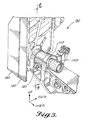
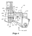
- the trunnion pin joint 90 includes eight basic elements: a trunnion pin 100, a landing gear fitting 110, an inboard nose wheel well fitting 130, a nose wheel well web 135, an outboard nose wheel well fitting 140, an inboard bushing 132 and an outboard bushing 142 and an outboard bushing retention clip 150.
- Trunnion pin 100 is secured to landing gear fitting 110 by a retention bolt 120 which passes through cylindrical bores in the landing gear fitting (not shown) and corresponding bores in the trunnion pin (not shown).
- Inboard nose wheel well fitting 130 and outboard nose wheel well fitting 140 are mounted on opposite sides of nose wheel well web 135.
- outboard bushing 142 is fitted into an opposite cylindrical bore in outboard nose wheel well fitting 140.
- Both outboard bushing 142 and inboard bushing 132 concentrically receive trunnion pin 100.
- Nose wheel well web 135 has an opening adapted to clear trunnion pin 100.
- both inboard and outboard bushings 132 and 142 have lubrication channels 148 formed in their inside surfaces to allow continuous lubrication of the trunnion pin and bushing surfaces. Lubricant is replenished to these channels through a lubrication fitting 146.
- Both inboard and outboard bushings 132 and 142 have outer flanges 133 and 149 respectively.
- Retaining clip 150 clamps down on an outer flange 149 of outboard bushing 142 and prevents it from migrating outboard and away from the trunnion pin joint.
- Figure 5 is a view of the trunnion pin joint 90 from the outside of the nose wheel well and it shows that retaining clip 150 is secured to outboard nose wheel well fitting 140 by retaining clip bolt 152.
- Figs. 1 and 2 landing gear 12 shock strut assembly 10 drag brace members 20 trunnion pins 30 bushings 40 landing gear support fittings 45 self-lubricating bearing 50 cylindrical steel pin 60 cylindrical bushing 70 Figs. 3, 4 and 5 trunnion pin joint 90 trunnion pin 100 landing geaar fitting 110 shims 115 retention bolt 120 inboard outboard nose wheel well fitting 130/140 inboard bushing 132 inboard bushing outer flange 133 wheel well web 135 outboard bushing 142 lubrification fitting 146 lubrification channels 148 outboard bushing outer flange 149 retaining clip 150 retaining clip bolt 152
Landscapes
- Engineering & Computer Science (AREA)
- Mechanical Engineering (AREA)
- Aviation & Aerospace Engineering (AREA)
- General Details Of Gearings (AREA)
- Gears, Cams (AREA)
- Gear Transmission (AREA)
- Snaps, Bayonet Connections, Set Pins, And Snap Rings (AREA)
Claims (7)
- Flugzeugbugfahrwerk-System umfassend:wobei die Zapfenverbindung (90) einen Zapfen (100), eine Fahrwerk-Halterung (110), mindestens eine an der Bugradschacht-Bahn (135) angebrachte Bugradschachthalterung (130, 140), eine Innenhülse (132) und eine Außenhülse (142), die in der mindestens einen Bugradschachthalterung (130, 140) angeordnet sind, und Sicherungsmittel zur Sicherung der Außenhülse (142) aufweist,eine Bugradschacht-Anordnung, die eine Bugradschacht-Bahn (135) auf jeder Seite des Bugradschachts beinhaltet, undeine Fahrwerk-Baugruppe, die mittels mindestens einer Zapfen-Verbindung (90) schwenkbar in der jeweiligen Bugradschacht-Bahn (135) angebracht ist,
dadurch gekennzeichnet, dass die Sicherungsmittel einen Sicherungsbügel (150) beinhalten. - Flugzeugbugfahrwerk-System gemäß Anspruch 1,
dadurch gekennzeichnet, dass die Außenhülse (142) einen äußeren Flansch (149) beinhaltet und der Sicherungsbügel (150) derart ausgestaltet ist, dass er auf den äußeren Flansch (149) klemmt. - Flugzeugbugfahrwerk-System gemäß Anspruch 1 oder 2,
dadurch gekennzeichnet, dass der Sicherungsbügel (150) durch einen Sicherungsbügel-Bolzen (152) an der mindestens einen Bugradschachthalterung (130, 140) gesichert ist. - Flugzeugbugfahrwerk-System gemäß einem der vorhergehenden Ansprüche, gekennzeichnet durch eine Innen-Bugradschachthalterung (130) und eine Außen-Bugradschachthalterung (140), die an gegenüberliegenden Seiten jeder Bugradschacht-Bahn (135) angebracht sind,
wobei die Innen- und Außenhülsen (132, 142) symmetrisch in der Innen- bzw. Außen-Bugradschachthalterung (130, 140) angebracht sind. - Flugzeugbugfahrwerk-System gemäß einem der vorhergehenden Ansprüche,
dadurch gekennzeichnet, dass der Zapfen (100) durch einen Sicherungsbolzen (120), der durch Bohrungen in der Fahrwerk-Halterung (110) und dem Zapfen (100) durchgeführt ist, an der Fahrwerk-Halterung (110) gesichert ist. - Flugzeugbugfahrwerk-System gemäß einem der vorhergehenden Ansprüche,
dadurch gekennzeichnet, dass die Fahrwerk-Baugruppe eine Federbein-Baugruppe und Knickstreben-Elemente enthält, wobei sowohl die Federbein-Baugruppe als auch die Knickstreben-Elemente kürzer sind als ein Freiraum zwischen den Bugradschacht-Bahnen (135), wobei sowohl die Federbein-Baugruppe als auch die Knickstreben-Elemente zwei Halterungen (110) an jedem Ende davon aufweisen, und wobei sowohl die Federbein-Baugruppe als auch die Knickstreben-Elemente durch den Zapfen (100), der durch eine der Federbein- oder Knickstrebenhalterungen (110) und die entsprechenden Innen- bzw. Außenhülsen (132, 142) durchgeführt ist, an der jeweiligen Bugradschacht-Bahn (135) angebracht sind. - Flugzeugbugfahrwerk-System gemäß Anspruch 6,
gekennzeichnet durch Unterlegscheiben (115), die eine Lücke zwischen den Fahrwerk-Halterungen (110) und den Innenhülsen (132) schließen.
Applications Claiming Priority (2)
| Application Number | Priority Date | Filing Date | Title |
|---|---|---|---|
| US918336 | 1997-08-26 | ||
| US08/918,336 US6016995A (en) | 1997-08-26 | 1997-08-26 | Aircraft nose landing gear |
Publications (3)
| Publication Number | Publication Date |
|---|---|
| EP0899191A2 EP0899191A2 (de) | 1999-03-03 |
| EP0899191A3 EP0899191A3 (de) | 1999-03-31 |
| EP0899191B1 true EP0899191B1 (de) | 2003-10-15 |
Family
ID=25440207
Family Applications (1)
| Application Number | Title | Priority Date | Filing Date |
|---|---|---|---|
| EP98202425A Expired - Lifetime EP0899191B1 (de) | 1997-08-26 | 1998-07-17 | Flugzeugbugfahrwerk |
Country Status (5)
| Country | Link |
|---|---|
| US (2) | US6016995A (de) |
| EP (1) | EP0899191B1 (de) |
| CN (1) | CN1093066C (de) |
| CA (1) | CA2243075C (de) |
| DE (1) | DE69818927T2 (de) |
Families Citing this family (22)
| Publication number | Priority date | Publication date | Assignee | Title |
|---|---|---|---|---|
| FR2793210B1 (fr) * | 1999-05-05 | 2001-09-21 | Aerospatiale Airbus | Structure d'attache d'un train d'atterrissage a un fuselage d'aeronef |
| US7264398B2 (en) | 2001-08-24 | 2007-09-04 | The Boeing Company | Truck pivot joint bearing and method of lubricating |
| FR2833572B1 (fr) * | 2001-12-18 | 2004-04-02 | Airbus France | Procede et dispositif de montage d'un train d'atterrissage sur une structure d'aeronef et aeronef comportant un tel train |
| FR2840585B1 (fr) | 2002-06-10 | 2005-02-04 | Airbus France | Dispositif de montage d'un train d'atterrissage sur une structure d'aeronef |
| US6824100B1 (en) * | 2003-08-15 | 2004-11-30 | The Boeing Company | Airplane landing gear |
| FR2893589B1 (fr) * | 2005-11-21 | 2009-06-05 | Airbus France Sas | Atterriseur d'aeronef comprenant un dispositif de manoeuvre a contrefiche et aeronef le comprenant |
| FR2893588B1 (fr) | 2005-11-21 | 2008-02-01 | Airbus France Sas | Case de train a structure en caissons |
| FR2893587B1 (fr) * | 2005-11-21 | 2009-06-05 | Airbus France Sas | Case de train a structure dissociee |
| US7546979B1 (en) * | 2006-09-15 | 2009-06-16 | The Boeing Company | Trapezoidal panel pin joint allowing free deflection between fuselage and wing |
| FR2917369B1 (fr) * | 2007-06-15 | 2009-08-07 | Airbus France Sas | Case de train d'atterrissage a encombrement reduit |
| WO2009097192A2 (en) * | 2008-01-28 | 2009-08-06 | Bell Helicopter Textron Inc. | Split pivot fitting for helicopter landing gear |
| FR2944076B1 (fr) * | 2009-04-06 | 2012-09-21 | Messier Dowty Sa | Dispositif de transmission selective d'effort, et un atterrisseur faisant application |
| GB201110483D0 (en) * | 2011-06-21 | 2011-08-03 | Airbus Operations Ltd | Pivot joint assembly |
| FR2983826B1 (fr) * | 2011-12-12 | 2013-12-20 | Airbus Operations Sas | Structure avant d'avion perfectionnee a compartiment pour train d'atterrissage. |
| US9140302B2 (en) | 2013-06-13 | 2015-09-22 | The Boeing Company | Joint bearing lubricant system |
| US9821904B2 (en) * | 2014-11-10 | 2017-11-21 | Goodrich Corporation | Landing gear with structural load path diverter bracket |
| US10598251B2 (en) * | 2017-04-14 | 2020-03-24 | The Boeing Company | Vibration damping link and method therefore |
| US11312483B2 (en) | 2019-05-10 | 2022-04-26 | Goodrich Corporation | Landing gear with hydraulic fluid channels |
| US11167865B2 (en) * | 2019-05-10 | 2021-11-09 | Goodrich Corporation | Additively manufactured lubrication channels |
| CN110466733B (zh) * | 2019-08-12 | 2022-07-19 | 中国航空工业集团公司沈阳飞机设计研究所 | 一种无人机起落架安装框 |
| US11897602B2 (en) | 2021-03-17 | 2024-02-13 | The Boeing Company | Support structure for an aircraft landing gear |
| US12466581B2 (en) * | 2023-05-08 | 2025-11-11 | The Boeing Company | Chock for steering mechanism of an aircraft nose landing gear |
Family Cites Families (10)
| Publication number | Priority date | Publication date | Assignee | Title |
|---|---|---|---|---|
| GB576547A (en) * | 1944-09-12 | 1946-04-09 | Walter Raylor | Improvements in pipe or tube couplings |
| US3393883A (en) * | 1966-06-06 | 1968-07-23 | Ted Smith Aircraft Company Inc | Aircraft landing gear |
| US4392623A (en) * | 1980-12-22 | 1983-07-12 | The Boeing Company | Fused connection adapted to fail under different overloads acting in different directions |
| FR2502578A1 (fr) * | 1981-03-27 | 1982-10-01 | Messier Hispano Sa | Train d'atterrissage du type tripode |
| US4720063A (en) * | 1985-09-30 | 1988-01-19 | The Boeing Company | Main landing gear with variable length drag brace |
| US4770372A (en) * | 1986-09-30 | 1988-09-13 | The Boeing Company | Two-stage aircraft landing gear |
| US5110068A (en) * | 1990-12-20 | 1992-05-05 | The Boeing Company | Multi-axled propped landing gear |
| FR2689087B1 (fr) * | 1992-03-31 | 1994-05-13 | Messier Bugatti | Atterrisseur relevable d'aerodynes, notamment pour helicopteres. |
| JP3147539B2 (ja) * | 1992-10-05 | 2001-03-19 | 本田技研工業株式会社 | 航空機の降着装置 |
| GB9223716D0 (en) * | 1992-11-12 | 1992-12-23 | British Aerospace | An aircraft landing gear trolley |
-
1997
- 1997-08-26 US US08/918,336 patent/US6016995A/en not_active Expired - Lifetime
-
1998
- 1998-07-13 CA CA002243075A patent/CA2243075C/en not_active Expired - Lifetime
- 1998-07-17 DE DE69818927T patent/DE69818927T2/de not_active Expired - Lifetime
- 1998-07-17 EP EP98202425A patent/EP0899191B1/de not_active Expired - Lifetime
- 1998-08-18 CN CN98118388A patent/CN1093066C/zh not_active Expired - Lifetime
-
1999
- 1999-08-05 US US09/368,556 patent/US6129310A/en not_active Expired - Lifetime
Also Published As
| Publication number | Publication date |
|---|---|
| CA2243075A1 (en) | 1999-02-26 |
| EP0899191A3 (de) | 1999-03-31 |
| EP0899191A2 (de) | 1999-03-03 |
| DE69818927T2 (de) | 2004-05-19 |
| US6016995A (en) | 2000-01-25 |
| CN1209406A (zh) | 1999-03-03 |
| CN1093066C (zh) | 2002-10-23 |
| DE69818927D1 (de) | 2003-11-20 |
| US6129310A (en) | 2000-10-10 |
| CA2243075C (en) | 2006-03-21 |
Similar Documents
| Publication | Publication Date | Title |
|---|---|---|
| EP0899191B1 (de) | Flugzeugbugfahrwerk | |
| US4243192A (en) | Ball pivot thrust bearing flex joint | |
| EP2660120B1 (de) | Schienenfahrzeugfahrgestell | |
| EP0741074A1 (de) | Ausfallsichere Triebwerksaufhängung durch drei Gestänge mit drei Hebeln | |
| US11479104B2 (en) | System and method for gas turbine engine mount with seal | |
| US4575145A (en) | Differential axle for railroad car | |
| US5897107A (en) | Roller bushing assembly | |
| PL177558B1 (pl) | Złącze dla pojazdu | |
| EP0504238B1 (de) | Fahrzeugachsträger und -bremsvorrichtung | |
| EP0520121B1 (de) | Achsschenkel | |
| US3458214A (en) | Rotary bearing | |
| EP0332311A1 (de) | Selbsteinstellendes Lager | |
| US4083610A (en) | Bearing assembly utilizing a tapered bushing holder | |
| US20020133950A1 (en) | Hole misalignment compensation system and method | |
| US20080095481A1 (en) | Differential wheel mounting for a railroad car | |
| CN223282501U (zh) | 矿用车差速器轴承座 | |
| US6413048B1 (en) | Elastomeric bearing | |
| US20210023927A1 (en) | System and method for gas turbine engine mount with seal | |
| US20170370417A1 (en) | Countersunk threaded bearing and method of installation | |
| US6604794B1 (en) | Uni-pilot hub/drum system | |
| EP0251545A1 (de) | Bremsanordnung | |
| US6595085B1 (en) | Differential bearing cap | |
| CN109250068A (zh) | 用于飞机缝翼滑轨的滑轮架 | |
| EP0561377B1 (de) | Wälzlager, insbesondere für ein Fahrzeugrad | |
| US2882079A (en) | Radial and longitudinal stressabsorbing suspension pivot |
Legal Events
| Date | Code | Title | Description |
|---|---|---|---|
| PUAI | Public reference made under article 153(3) epc to a published international application that has entered the european phase |
Free format text: ORIGINAL CODE: 0009012 |
|
| PUAL | Search report despatched |
Free format text: ORIGINAL CODE: 0009013 |
|
| AK | Designated contracting states |
Kind code of ref document: A2 Designated state(s): DE FR GB |
|
| AX | Request for extension of the european patent |
Free format text: AL;LT;LV;MK;RO;SI |
|
| AK | Designated contracting states |
Kind code of ref document: A3 Designated state(s): AT BE CH CY DE DK ES FI FR GB GR IE IT LI LU MC NL PT SE |
|
| AX | Request for extension of the european patent |
Free format text: AL;LT;LV;MK;RO;SI |
|
| 17P | Request for examination filed |
Effective date: 19990922 |
|
| AKX | Designation fees paid |
Free format text: DE FR GB |
|
| 17Q | First examination report despatched |
Effective date: 20020806 |
|
| GRAH | Despatch of communication of intention to grant a patent |
Free format text: ORIGINAL CODE: EPIDOS IGRA |
|
| RIN1 | Information on inventor provided before grant (corrected) |
Inventor name: DONG, ANNETTE K. Inventor name: DEPENBUSCH, ROGER A. Inventor name: SQUIRES, THOMAS J. |
|
| GRAS | Grant fee paid |
Free format text: ORIGINAL CODE: EPIDOSNIGR3 |
|
| GRAA | (expected) grant |
Free format text: ORIGINAL CODE: 0009210 |
|
| AK | Designated contracting states |
Kind code of ref document: B1 Designated state(s): DE FR GB |
|
| REG | Reference to a national code |
Ref country code: GB Ref legal event code: FG4D |
|
| REF | Corresponds to: |
Ref document number: 69818927 Country of ref document: DE Date of ref document: 20031120 Kind code of ref document: P |
|
| ET | Fr: translation filed | ||
| PLBQ | Unpublished change to opponent data |
Free format text: ORIGINAL CODE: EPIDOS OPPO |
|
| PLBI | Opposition filed |
Free format text: ORIGINAL CODE: 0009260 |
|
| PLAX | Notice of opposition and request to file observation + time limit sent |
Free format text: ORIGINAL CODE: EPIDOSNOBS2 |
|
| 26 | Opposition filed |
Opponent name: AIRBUS SAS Effective date: 20040715 |
|
| PLAX | Notice of opposition and request to file observation + time limit sent |
Free format text: ORIGINAL CODE: EPIDOSNOBS2 |
|
| PLBB | Reply of patent proprietor to notice(s) of opposition received |
Free format text: ORIGINAL CODE: EPIDOSNOBS3 |
|
| PLBD | Termination of opposition procedure: decision despatched |
Free format text: ORIGINAL CODE: EPIDOSNOPC1 |
|
| PLBP | Opposition withdrawn |
Free format text: ORIGINAL CODE: 0009264 |
|
| PLBM | Termination of opposition procedure: date of legal effect published |
Free format text: ORIGINAL CODE: 0009276 |
|
| STAA | Information on the status of an ep patent application or granted ep patent |
Free format text: STATUS: OPPOSITION PROCEDURE CLOSED |
|
| 27C | Opposition proceedings terminated |
Effective date: 20070312 |
|
| REG | Reference to a national code |
Ref country code: FR Ref legal event code: PLFP Year of fee payment: 19 |
|
| REG | Reference to a national code |
Ref country code: FR Ref legal event code: PLFP Year of fee payment: 20 |
|
| PGFP | Annual fee paid to national office [announced via postgrant information from national office to epo] |
Ref country code: FR Payment date: 20170726 Year of fee payment: 20 Ref country code: DE Payment date: 20170727 Year of fee payment: 20 Ref country code: GB Payment date: 20170727 Year of fee payment: 20 |
|
| REG | Reference to a national code |
Ref country code: DE Ref legal event code: R071 Ref document number: 69818927 Country of ref document: DE |
|
| REG | Reference to a national code |
Ref country code: GB Ref legal event code: PE20 Expiry date: 20180716 |
|
| PG25 | Lapsed in a contracting state [announced via postgrant information from national office to epo] |
Ref country code: GB Free format text: LAPSE BECAUSE OF EXPIRATION OF PROTECTION Effective date: 20180716 |