EP0899453A2 - Dispositif d'alimentation en carburant - Google Patents
Dispositif d'alimentation en carburant Download PDFInfo
- Publication number
- EP0899453A2 EP0899453A2 EP98114763A EP98114763A EP0899453A2 EP 0899453 A2 EP0899453 A2 EP 0899453A2 EP 98114763 A EP98114763 A EP 98114763A EP 98114763 A EP98114763 A EP 98114763A EP 0899453 A2 EP0899453 A2 EP 0899453A2
- Authority
- EP
- European Patent Office
- Prior art keywords
- fuel
- pressure
- low pressure
- orifice
- supply apparatus
- Prior art date
- Legal status (The legal status is an assumption and is not a legal conclusion. Google has not performed a legal analysis and makes no representation as to the accuracy of the status listed.)
- Granted
Links
Images
Classifications
-
- F—MECHANICAL ENGINEERING; LIGHTING; HEATING; WEAPONS; BLASTING
- F02—COMBUSTION ENGINES; HOT-GAS OR COMBUSTION-PRODUCT ENGINE PLANTS
- F02M—SUPPLYING COMBUSTION ENGINES IN GENERAL WITH COMBUSTIBLE MIXTURES OR CONSTITUENTS THEREOF
- F02M37/00—Apparatus or systems for feeding liquid fuel from storage containers to carburettors or fuel-injection apparatus; Arrangements for purifying liquid fuel specially adapted for, or arranged on, internal-combustion engines
- F02M37/0011—Constructional details; Manufacturing or assembly of elements of fuel systems; Materials therefor
- F02M37/0041—Means for damping pressure pulsations
-
- F—MECHANICAL ENGINEERING; LIGHTING; HEATING; WEAPONS; BLASTING
- F02—COMBUSTION ENGINES; HOT-GAS OR COMBUSTION-PRODUCT ENGINE PLANTS
- F02M—SUPPLYING COMBUSTION ENGINES IN GENERAL WITH COMBUSTIBLE MIXTURES OR CONSTITUENTS THEREOF
- F02M55/00—Fuel-injection apparatus characterised by their fuel conduits or their venting means; Arrangements of conduits between fuel tank and pump F02M37/00
- F02M55/04—Means for damping vibrations or pressure fluctuations in injection pump inlets or outlets
-
- F—MECHANICAL ENGINEERING; LIGHTING; HEATING; WEAPONS; BLASTING
- F02—COMBUSTION ENGINES; HOT-GAS OR COMBUSTION-PRODUCT ENGINE PLANTS
- F02M—SUPPLYING COMBUSTION ENGINES IN GENERAL WITH COMBUSTIBLE MIXTURES OR CONSTITUENTS THEREOF
- F02M63/00—Other fuel-injection apparatus having pertinent characteristics not provided for in groups F02M39/00 - F02M57/00 or F02M67/00; Details, component parts, or accessories of fuel-injection apparatus, not provided for in, or of interest apart from, the apparatus of groups F02M39/00 - F02M61/00 or F02M67/00; Combination of fuel pump with other devices, e.g. lubricating oil pump
- F02M63/02—Fuel-injection apparatus having several injectors fed by a common pumping element, or having several pumping elements feeding a common injector; Fuel-injection apparatus having provisions for cutting-out pumps, pumping elements, or injectors; Fuel-injection apparatus having provisions for variably interconnecting pumping elements and injectors alternatively
- F02M63/0225—Fuel-injection apparatus having a common rail feeding several injectors ; Means for varying pressure in common rails; Pumps feeding common rails
-
- F—MECHANICAL ENGINEERING; LIGHTING; HEATING; WEAPONS; BLASTING
- F02—COMBUSTION ENGINES; HOT-GAS OR COMBUSTION-PRODUCT ENGINE PLANTS
- F02M—SUPPLYING COMBUSTION ENGINES IN GENERAL WITH COMBUSTIBLE MIXTURES OR CONSTITUENTS THEREOF
- F02M37/00—Apparatus or systems for feeding liquid fuel from storage containers to carburettors or fuel-injection apparatus; Arrangements for purifying liquid fuel specially adapted for, or arranged on, internal-combustion engines
- F02M37/0047—Layout or arrangement of systems for feeding fuel
Definitions
- the present invention relates to a fuel supply apparatus, and in particular, to a pulsation reducing structure of a fuel supply apparatus for reducing pulsation generated by an operation of a pressure regulator.
- the pressure of fuel supplied to a high pressure pump has been conventionally reduced below a predetermined pressure by disposing a pressure regulator in the low pressure fuel passage for supplying the fuel pumped out from a fuel tank by the low pressure pump to the high pressure pump or in the low pressure fuel passage disposed in the high pressure pump.
- the pressure pulsation generated by the pressure regulator is transmitted in the fuel pipe for supplying the low pressure fuel to the high pressure pump, and produces noises.
- a fuel filter is disposed in the fuel pipe which connects a low pressure pump and the high pressure pump, and is mounted to a vehicle body, the vibration of the fuel filter caused by the pressure pulsation is transmitted to the vehicle body and cause large noise in the car.
- a pulsation damper of diaphragm type may be connected to the fuel pipe to reduce such pressure pulsation.
- the frequency of the pressure pulsation generated by the pressure regulator is high, and the pulsation damper of diaphragm type can not respond to such high frequency of the pressure pulsation.
- the amplitude of the pressure pulsation is large, it may be a problem that the diaphragm may be broken.
- a cross sectional area S 0 of a first low pressure fuel passage which is connected to a high pressure pump and which has a pressure regulator, a cross sectional area S 1 of an orifice formed between the first low pressure fuel passage and a second low pressure fuel passage, and a cross sectional area S 2 of the second low pressure fuel passage for supplying the low pressure fuel to the first low pressure fuel passage are set to satisfy a relationship of S 1 ⁇ S 0 ⁇ S 2 .
- the pressure pulsation generated at the pressure regulator and normally turned and reflected at a boundary between the first low pressure fuel passage and the orifice is canceled by the pressure pulsation reversely turned and reflected at a boundary between the orifice and the second low pressure fuel passage. Therefore, the pressure pulsation generated at the pressure regulator is reduced, and the noise produced by the fuel supply apparatus is reduced.
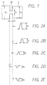
- FIG. 3 A fuel supply system using a fuel supply apparatus according to a preferred embodiment of the present invention is shown in FIG. 3.
- the fuel supply apparatus comprises fuel pipes 2 and 3, a fuel filter 4, a high pressure pump 5, a pressure regulator 7 and a fuel return pipe 13 which will be described below.
- Foreign substance is removed, from the fuel pumped up from a fuel tank 6 by a low pressure pump 1, by the fuel filter 4 disposed between the fuel pipe 2 and the fuel pipe 3.
- the fuel passed through the fuel filter 4 is pressurized by the high pressure pump 5, and is supplied to injectors 12, which are fuel injection devices fixed to a branch pipe 10, from a delivery valve 9.
- the fuel pipes 2 and 3 and the fuel filter 4 are included in a low pressure fuel passage.
- the pressure regulator 7 regulates the pressure of the fuel to be sucked into the high pressure pump 5 to maintain it below a predetermined pressure, and is connected to the low pressure fuel passage in the high pressure pump 5. When the pressure of the sucked fuel exceeds a predetermined pressure, the pressure regulator 7 opens its valve to return the excessive fuel to the fuel tank 6 through a fuel return pipe 13.
- the fuel return pipe 13 is also included in the low pressure fuel passage.
- an orifice 20 is formed at the fuel exit, which is a connection part of the fuel filter 4 and the fuel pipe 3, of the fuel filter 4.
- the cross sectional area of the fuel pipe 3 connected to the high pressure pump 5 is S 0
- the cross sectional area of the orifice 20 is S 1
- the cross sectional area of the fuel filter 4, disposed at the position opposite to the high pressure pump 5 of the orifice 20 is S 2
- there is a relationship of S 1 ⁇ S 0 ⁇ S 2 there is a relationship of S 1 ⁇ S 0 ⁇ S 2 .
- the pulsation reducing structure is formed by the relationship of S 1 ⁇ S 0 ⁇ S 2 .
- the pressure regulator 7 opens its valve to return the excessive fuel to the fuel tank 6 via the fuel return pipe 13.
- the valve of the pressure regulator 7 is detached from a valve seat thereof and the fuel passes through an opening between the valve and the valve seat, negative pressure is generated at the opening and produces cavitation. Furthermore, when the produced cavitation disappears, a large pressure wave is generated.
- a pressure pulsation is generated.
- P 3 is negative because (S 1 - S 2 ) ⁇ 0.
- the waveforms of the pressure pulsations shown by the equation (1) and the equation (4) are shifted from each other according to the difference of the round-trip distance of the orifice 20 (that is L ⁇ 2), and the directions of the pressure thereof are opposite to each other. Therefore, by making the length L of the orifice 20 as short as possible to reduce a shift in the waveform, the pressure pulsation shown in FIG. 2B and the pressure pulsation shown in FIG. 2E cancel each other out to reduce the pressure P.
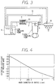
- the inner diameter of the fuel pipe 3 is 5. 5 mm and the inner diameter of the fuel filter 4 is 60 mm. Therefore, the coefficient of the pressure P 0 in the right side of the equation (5) can be reduced to approximately zero by adjusting the inner diameter d of the orifice 20. If the inner diameter d of the orifice 20 is too small, the necessary amount of fuel may not be supplied to the high pressure pump 5. Furthermore, if the fuel pumped up by the low pressure pump 1 is blocked by the orifice 20, the pressure of the fuel in the fuel pipe 2 increases and the low pressure pump 1 might be broken.
- the right side of the equation (5) can be approximately zero by setting the inner diameter d of the orifice 20 at 2. 65 mm as shown in FIG. 4.
- the pressure pulsation can be reduced to some extent by setting the inner diameter d of the orifice 20 at 2 mm ⁇ d ⁇ 4 mm. Since the length L of the orifice 20 is 1 mm, in other words, both ends of the orifice 20 are brought closer each other, the pressure pulsation normally turned and reflected at the boundary between the cross sectional area S 0 and the cross sectional area S 1 of the orifice 20 and the pressure pulsation reversely turned and reflected at the boundary between the cross sectional area S 1 of the orifice 20 and the cross sectional area S 2 are shifted very little in time, and cancel each other. Therefore, the pressure pulsation is reliably reduced.
- the fuel supply apparatus does not reduce the pressure pulsation by the displacement of a movable member as in the case of the damper of diaphragm type, the members are hardly broken even if the amplitude of the pressure pulsation becomes large.
- the fuel filter 4 since the fuel filter 4 has the cross sectional area S 2 , it is not necessary to manufacture a structure for forming the cross sectional area S 2 . Further, although a distance between the pressure regulator 7 and the fuel filter 4 is made smaller by disposing the fuel filter 4 in the fuel pipes 2 and 3 to make the frequency of the pressure pulsation transmitted to the fuel filter 4 from the pressure regulator 7 higher, the pressure pulsation is reduced by a difference in the cross sectional area irrespective of the higher frequency.
- one orifice 20 is formed at the fuel exit of the fuel filter 4.
- several orifices may be formed in the same plane instead.
- the diameter d of each orifice is required to be 2 mm ⁇ d ⁇ 4 mm.
- the orifice 20 is provided in the fuel pipes 2 and 3 of the fuel supply side to constitute a pressure reducing structure, the orifice may be formed in the fuel return pipe 13 instead.
- the fuel filter 4 is provided between the fuel pipes 2 and 3, the fuel filter 4 may be connected to the low pressure pump 1 instead. Further, although the pressure regulator 7 is connected to the high pressure pump 5, the pressure regulator 7 may be installed in the fuel pipe, which connects the low pressure pump 1 and the high pressure pump 5, at the high pressure pump 5 side of the fuel filter 4.
- a fuel supply apparatus having a cross sectional area S 0 of a first low pressure fuel passage (3) which is connected to a high pressure pump (5) and which has a pressure regulator (7), a cross sectional area S 1 of an orifice (20) formed between the first low pressure fuel passage (3) and a second low pressure fuel passage (2), and a cross sectional area S 2 of the second low pressure fuel passage (2) for supplying the low pressure fuel to the first low pressure fuel passage (3).
- Those cross sectional areas are set to satisfy a relationship of S 1 ⁇ S 0 ⁇ S 2 such that the pressure pulsation generated at the pressure regulator (7) is reduced, and the noise produced by the fuel supply apparatus is reduced.
Landscapes
- Engineering & Computer Science (AREA)
- Chemical & Material Sciences (AREA)
- Combustion & Propulsion (AREA)
- Mechanical Engineering (AREA)
- General Engineering & Computer Science (AREA)
- Fuel-Injection Apparatus (AREA)
Applications Claiming Priority (3)
| Application Number | Priority Date | Filing Date | Title |
|---|---|---|---|
| JP9234075A JPH1172053A (ja) | 1997-08-29 | 1997-08-29 | 燃料供給装置 |
| JP23407597 | 1997-08-29 | ||
| JP234075/97 | 1997-08-29 |
Publications (3)
| Publication Number | Publication Date |
|---|---|
| EP0899453A2 true EP0899453A2 (fr) | 1999-03-03 |
| EP0899453A3 EP0899453A3 (fr) | 2001-12-05 |
| EP0899453B1 EP0899453B1 (fr) | 2003-10-15 |
Family
ID=16965214
Family Applications (1)
| Application Number | Title | Priority Date | Filing Date |
|---|---|---|---|
| EP98114763A Expired - Lifetime EP0899453B1 (fr) | 1997-08-29 | 1998-08-05 | Dispositif d'alimentation en carburant |
Country Status (4)
| Country | Link |
|---|---|
| US (1) | US6021759A (fr) |
| EP (1) | EP0899453B1 (fr) |
| JP (1) | JPH1172053A (fr) |
| DE (1) | DE69818929T2 (fr) |
Cited By (3)
| Publication number | Priority date | Publication date | Assignee | Title |
|---|---|---|---|---|
| FR2848256A1 (fr) * | 2002-12-04 | 2004-06-11 | Renault Sa | Dispositif d'amortissement des ondes de pression pour systeme d'injection de carburant |
| WO2008115462A3 (fr) * | 2007-03-21 | 2008-11-06 | Continental Automotive Systems | Réduction de bruit d'écoulement de régulateur pour système de carburant de véhicule |
| GB2526913A (en) * | 2014-04-03 | 2015-12-09 | Ford Global Tech Llc | Fuel injection system and vehicle drive equipped therewith, together with motor vehicle and method for operating a fuel injection system |
Families Citing this family (11)
| Publication number | Priority date | Publication date | Assignee | Title |
|---|---|---|---|---|
| DE19740057C1 (de) * | 1997-09-12 | 1999-01-21 | Mannesmann Vdo Ag | Kraftstoffversorgungssystem |
| DE19857249A1 (de) * | 1998-12-11 | 2000-06-15 | Bosch Gmbh Robert | Kraftstoffeinspritzsystem |
| US6142127A (en) * | 1999-01-25 | 2000-11-07 | Siemens Automotive Corporation | Restriction structure for reducing gas formation in a high pressure fuel return line |
| WO2000055495A1 (fr) * | 1999-03-17 | 2000-09-21 | Hitachi, Ltd. | Pompe d'alimentation en combustible |
| JP2000291509A (ja) * | 1999-04-01 | 2000-10-17 | Mitsubishi Electric Corp | 直噴式ガソリンエンジン用燃料供給装置 |
| JP2008057451A (ja) * | 2006-08-31 | 2008-03-13 | Hitachi Ltd | 高圧燃料供給ポンプ |
| JP4803269B2 (ja) * | 2009-02-24 | 2011-10-26 | 株式会社デンソー | 脈動低減装置 |
| US20130312706A1 (en) * | 2012-05-23 | 2013-11-28 | Christopher J. Salvador | Fuel system having flow-disruption reducer |
| JP5672287B2 (ja) | 2012-10-11 | 2015-02-18 | 株式会社デンソー | 燃料噴射装置 |
| US9217236B2 (en) * | 2013-12-27 | 2015-12-22 | Komatsu Ltd. | Work vehicle |
| JP6409685B2 (ja) * | 2015-06-03 | 2018-10-24 | 株式会社デンソー | 燃料供給装置 |
Family Cites Families (12)
| Publication number | Priority date | Publication date | Assignee | Title |
|---|---|---|---|---|
| US3187733A (en) * | 1963-08-23 | 1965-06-08 | Int Harvester Co | Fuel injection system for internal combustion engines |
| US4526151A (en) * | 1982-03-12 | 1985-07-02 | Mitsubishi Jukogyo Kabushiki Kaisha | Fuel injection device |
| JPS58180374A (ja) * | 1982-04-16 | 1983-10-21 | 日本信号株式会社 | 列車の点制御式閉そく装置 |
| JP2929756B2 (ja) * | 1991-04-30 | 1999-08-03 | 株式会社デンソー | 蓄圧式燃料噴射制御装置 |
| US5297523A (en) * | 1993-02-26 | 1994-03-29 | Caterpillar Inc. | Tuned actuating fluid inlet manifold for a hydraulically-actuated fuel injection system |
| US5373824A (en) * | 1993-08-06 | 1994-12-20 | Ford Motor Company | Acoustical damping device for gaseous fueled automotive engines |
| US5365906A (en) * | 1993-12-20 | 1994-11-22 | Chrysler Corporation | Fluid flow check valve for fuel system |
| JP3567485B2 (ja) * | 1994-05-13 | 2004-09-22 | 株式会社デンソー | 燃料噴射ポンプ |
| JP2689226B2 (ja) * | 1994-12-02 | 1997-12-10 | 株式会社ゼクセル | 高圧燃料噴射装置用燃料ポンプ |
| JPH08261084A (ja) * | 1995-03-20 | 1996-10-08 | Nippondenso Co Ltd | 内燃機関の燃料供給装置 |
| EP0780569B1 (fr) * | 1995-12-19 | 2002-03-20 | Nippon Soken, Inc. | Dispositif d'injection de carburant avec accumulateur |
| DE19607070B4 (de) * | 1996-02-24 | 2013-04-25 | Robert Bosch Gmbh | Verfahren und Vorrichtung zur Steuerung einer Brennkraftmaschine |
-
1997
- 1997-08-29 JP JP9234075A patent/JPH1172053A/ja active Pending
-
1998
- 1998-08-03 US US09/127,870 patent/US6021759A/en not_active Expired - Fee Related
- 1998-08-05 EP EP98114763A patent/EP0899453B1/fr not_active Expired - Lifetime
- 1998-08-05 DE DE69818929T patent/DE69818929T2/de not_active Expired - Fee Related
Cited By (5)
| Publication number | Priority date | Publication date | Assignee | Title |
|---|---|---|---|---|
| FR2848256A1 (fr) * | 2002-12-04 | 2004-06-11 | Renault Sa | Dispositif d'amortissement des ondes de pression pour systeme d'injection de carburant |
| WO2008115462A3 (fr) * | 2007-03-21 | 2008-11-06 | Continental Automotive Systems | Réduction de bruit d'écoulement de régulateur pour système de carburant de véhicule |
| US7942130B2 (en) | 2007-03-21 | 2011-05-17 | Continental Automotive Systems Us, Inc. | Regulator flow noise prevention for fuel system of a vehicle |
| GB2526913A (en) * | 2014-04-03 | 2015-12-09 | Ford Global Tech Llc | Fuel injection system and vehicle drive equipped therewith, together with motor vehicle and method for operating a fuel injection system |
| GB2526913B (en) * | 2014-04-03 | 2021-02-10 | Ford Global Tech Llc | Fuel injection system and vehicle drive equipped therewith, together with motor vehicle and method for operating a fuel injection system |
Also Published As
| Publication number | Publication date |
|---|---|
| US6021759A (en) | 2000-02-08 |
| EP0899453B1 (fr) | 2003-10-15 |
| EP0899453A3 (fr) | 2001-12-05 |
| DE69818929D1 (de) | 2003-11-20 |
| JPH1172053A (ja) | 1999-03-16 |
| DE69818929T2 (de) | 2004-08-12 |
Similar Documents
| Publication | Publication Date | Title |
|---|---|---|
| EP0899453B1 (fr) | Dispositif d'alimentation en carburant | |
| US5107800A (en) | Suction apparatus for engine | |
| US6314942B1 (en) | Fuel pressure dampening element | |
| US6135092A (en) | Fuel injection system | |
| JPH08303313A (ja) | 内燃機関用燃料供給システム | |
| US6789529B2 (en) | Pulsation damping device in fuel pump module | |
| WO2002001064A1 (fr) | Dispositif d'alimentation en carburant d'un accumulateur | |
| KR19990006400A (ko) | 엔진의 연료공급장치 | |
| JP3395371B2 (ja) | 燃料噴射装置 | |
| WO2002036997A2 (fr) | Systeme et soupape de regulation de pression | |
| EP1231379B1 (fr) | Dispositif d'alimentation d'un moteur en carburant | |
| JPH08246984A (ja) | 内燃機関の燃料供給系脈動圧減衰装置 | |
| CA2430915A1 (fr) | Systemes de production de fluide et de carburant reduisant les fluctuations de pression, et moteurs ainsi pourvus | |
| US20050193984A1 (en) | Dispersion-type suppressor for acoustic noise reduction of a gaseous fuel injector | |
| KR100348349B1 (ko) | 자동차 연료공급시스템의 댐퍼장치 | |
| KR100440015B1 (ko) | 맥동 댐퍼 기능을 가진 연료 분배관 | |
| JP2000073907A (ja) | 内燃機関の燃料分配装置 | |
| JPH09195872A (ja) | 燃料供給装置 | |
| KR200154447Y1 (ko) | 연료필터 | |
| JPH1172057A (ja) | エンジンの燃料供給装置 | |
| JPH11270429A (ja) | 圧力脈動低減装置 | |
| JP3552457B2 (ja) | 合流装置 | |
| JPH0874694A (ja) | 燃料の脈動減衰装置 | |
| WO2000011344A1 (fr) | Systeme d'injection de carburant | |
| JP5680485B2 (ja) | 燃料圧力調整装置 |
Legal Events
| Date | Code | Title | Description |
|---|---|---|---|
| PUAI | Public reference made under article 153(3) epc to a published international application that has entered the european phase |
Free format text: ORIGINAL CODE: 0009012 |
|
| AK | Designated contracting states |
Kind code of ref document: A2 Designated state(s): AT BE CH CY DE DK ES FI FR GB GR IE IT LI LU MC NL PT SE Kind code of ref document: A2 Designated state(s): DE FR GB |
|
| AX | Request for extension of the european patent |
Free format text: AL;LT;LV;MK;RO;SI |
|
| PUAL | Search report despatched |
Free format text: ORIGINAL CODE: 0009013 |
|
| AK | Designated contracting states |
Kind code of ref document: A3 Designated state(s): AT BE CH CY DE DK ES FI FR GB GR IE IT LI LU MC NL PT SE |
|
| AX | Request for extension of the european patent |
Free format text: AL;LT;LV;MK;RO;SI |
|
| 17P | Request for examination filed |
Effective date: 20020205 |
|
| AKX | Designation fees paid |
Free format text: DE FR GB |
|
| 17Q | First examination report despatched |
Effective date: 20021028 |
|
| GRAH | Despatch of communication of intention to grant a patent |
Free format text: ORIGINAL CODE: EPIDOS IGRA |
|
| GRAS | Grant fee paid |
Free format text: ORIGINAL CODE: EPIDOSNIGR3 |
|
| GRAA | (expected) grant |
Free format text: ORIGINAL CODE: 0009210 |
|
| AK | Designated contracting states |
Kind code of ref document: B1 Designated state(s): DE FR GB |
|
| PG25 | Lapsed in a contracting state [announced via postgrant information from national office to epo] |
Ref country code: FR Free format text: LAPSE BECAUSE OF FAILURE TO SUBMIT A TRANSLATION OF THE DESCRIPTION OR TO PAY THE FEE WITHIN THE PRESCRIBED TIME-LIMIT Effective date: 20031015 |
|
| REG | Reference to a national code |
Ref country code: GB Ref legal event code: FG4D |
|
| REG | Reference to a national code |
Ref country code: IE Ref legal event code: FG4D |
|
| REF | Corresponds to: |
Ref document number: 69818929 Country of ref document: DE Date of ref document: 20031120 Kind code of ref document: P |
|
| PG25 | Lapsed in a contracting state [announced via postgrant information from national office to epo] |
Ref country code: GB Free format text: LAPSE BECAUSE OF NON-PAYMENT OF DUE FEES Effective date: 20040805 |
|
| PLBE | No opposition filed within time limit |
Free format text: ORIGINAL CODE: 0009261 |
|
| STAA | Information on the status of an ep patent application or granted ep patent |
Free format text: STATUS: NO OPPOSITION FILED WITHIN TIME LIMIT |
|
| 26N | No opposition filed |
Effective date: 20040716 |
|
| EN | Fr: translation not filed | ||
| PG25 | Lapsed in a contracting state [announced via postgrant information from national office to epo] |
Ref country code: DE Free format text: LAPSE BECAUSE OF NON-PAYMENT OF DUE FEES Effective date: 20050301 |
|
| GBPC | Gb: european patent ceased through non-payment of renewal fee |
Effective date: 20040805 |
|
| REG | Reference to a national code |
Ref country code: IE Ref legal event code: MM4A |