EP0899493B1 - Traversée de câble/tuyaux pour une ouverture dans un mur - Google Patents
Traversée de câble/tuyaux pour une ouverture dans un mur Download PDFInfo
- Publication number
- EP0899493B1 EP0899493B1 EP98114446A EP98114446A EP0899493B1 EP 0899493 B1 EP0899493 B1 EP 0899493B1 EP 98114446 A EP98114446 A EP 98114446A EP 98114446 A EP98114446 A EP 98114446A EP 0899493 B1 EP0899493 B1 EP 0899493B1
- Authority
- EP
- European Patent Office
- Prior art keywords
- packing
- ring
- packing ring
- parting line
- ring segments
- Prior art date
- Legal status (The legal status is an assumption and is not a legal conclusion. Google has not performed a legal analysis and makes no representation as to the accuracy of the status listed.)
- Expired - Lifetime
Links
- 238000012856 packing Methods 0.000 claims description 44
- 239000013013 elastic material Substances 0.000 claims description 2
- 238000003780 insertion Methods 0.000 claims description 2
- 230000037431 insertion Effects 0.000 claims description 2
- 210000004907 gland Anatomy 0.000 claims 6
- 238000007789 sealing Methods 0.000 abstract description 26
- 239000004033 plastic Substances 0.000 abstract description 2
- 230000002093 peripheral effect Effects 0.000 abstract 1
- 238000005452 bending Methods 0.000 description 6
- 230000009969 flowable effect Effects 0.000 description 1
- 238000002347 injection Methods 0.000 description 1
- 239000007924 injection Substances 0.000 description 1
- 238000009434 installation Methods 0.000 description 1
- 239000000463 material Substances 0.000 description 1
- 238000000034 method Methods 0.000 description 1
- 239000002991 molded plastic Substances 0.000 description 1
- XLYOFNOQVPJJNP-UHFFFAOYSA-N water Substances O XLYOFNOQVPJJNP-UHFFFAOYSA-N 0.000 description 1
Images




Classifications
-
- F—MECHANICAL ENGINEERING; LIGHTING; HEATING; WEAPONS; BLASTING
- F16—ENGINEERING ELEMENTS AND UNITS; GENERAL MEASURES FOR PRODUCING AND MAINTAINING EFFECTIVE FUNCTIONING OF MACHINES OR INSTALLATIONS; THERMAL INSULATION IN GENERAL
- F16L—PIPES; JOINTS OR FITTINGS FOR PIPES; SUPPORTS FOR PIPES, CABLES OR PROTECTIVE TUBING; MEANS FOR THERMAL INSULATION IN GENERAL
- F16L5/00—Devices for use where pipes, cables or protective tubing pass through walls or partitions
- F16L5/02—Sealing
- F16L5/08—Sealing by means of axial screws compressing a ring or sleeve
-
- H—ELECTRICITY
- H02—GENERATION; CONVERSION OR DISTRIBUTION OF ELECTRIC POWER
- H02G—INSTALLATION OF ELECTRIC CABLES OR LINES, OR OF COMBINED OPTICAL AND ELECTRIC CABLES OR LINES
- H02G3/00—Installations of electric cables or lines or protective tubing therefor in or on buildings, equivalent structures or vehicles
- H02G3/22—Installations of cables or lines through walls, floors or ceilings, e.g. into buildings
Definitions
- the invention relates to a sealing packing for insertion into a wall opening for the purpose of passing lines. Both energy and and telephone cables as well as pipelines for flowable media such as water or gas into consideration.
- Such a packing comprises a rubber-made sealing washer Material with a circular circumference, furthermore pressing elements on both sides the sealing washer and the sealing washer sandwich enclose between themselves. Through the entire packing are also Tension rods passed through, with which the pressing elements on both sides can be clamped so that the sealing washer is squeezed, whereby their outer diameter increases, so that the sealing washer creates the wall reveal.
- the device is installed as follows:
- the packing is inserted into the wall opening and fixed in it.
- the cables are then passed through the hole in the Seal pack passed through.
- the tension bolts are not initially stretched so that the sealing washer is not yet squeezed together becomes.
- the clamping screws for the purpose of fixing the Sealing packing tightened.
- the embodiment mentioned facilitates the assembly of sealing packs over previous embodiments, but is still room for improvement.
- the invention is therefore based on the object To design a packing according to the preamble of claim 1 in such a way that the assembly is made even easier, without additional structural Expenditure.
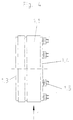
- the sealing packing 1 shown in FIG. 1 comprises a sealing ring 1.1 rubber-elastic material.
- the ring 1.1 is with a circumferential groove 1.2 Mistake. It is encased on both sides by ring segments 1.3, 1.4.
- a plurality of clamping screws 1.5 are over the circumference of the sealing packing evenly distributed.
- the sealing pack sits in a plastic sleeve.
- the sleeve points to her Inside a circumferential collar 2.1, which in the circumferential groove 1.2 intervenes.
- the federal government 2.1 can be interrupted or closed.
- the sleeve 2 is poured into a concrete wall 3.
- the packing 1 encloses a pipeline 4 for the passage of gas.
- the sealing ring 1.1 is shown by itself. You can see that he has a parting line 1.6.
- the parting line is, as you can see, against the Radial plane inclined. In the present case, the angle of inclination is approximately 45 °. However, other angles are also conceivable, for example 10, 20, 30, 40, 50, 60, 70 °.
- Figure 3 is a top view of the entire packing. As you can see, there are three ring segments 1.3.1, 1.3.2 on the page shown here and 1.3.3. The ring segments are on the opposite side identical in shape to the ones here and are present in the projection same place.
- a joint 1.7 runs in the same way as the joint 1.6 in the sealing ring 1.1 between the two ring segments 1.3.1, 1.3.3.
- the parting line 1.6 in the Sealing ring 1.1 shown here in dashed lines, runs, as you can see, in Area of the joint 1.7.
- the two parting lines can also collapse.
- the angle of inclination that the two joints with the Radial plane concerned can be the same. It is also possible the angle that the parting line 1.6 forms with the radial plane, to make larger or smaller than the one that the parting line 1.7 with the radial plane in question.
- Figure 5 is very revealing because it is the assembly process illustrated. As you can see, due to the joints 1.6 of the Sealing ring 1.1 and the parting line 1.7 between the relevant Ring segments a bending of the entire packing 1 possible, and an imaginary momentary bending axis 1.8 parallel to the Longitudinal axis of the packing 1 runs and between the ring segments 1.3.1 and 1.3.2. lies. After bending or pulling in one branch the packing around the bending axis 1.8 can bend one more imaginary momentary bending axis 1.9 can be made. This is located between the ring segments 1.3.2 and 1.3.3. Figure 5 shows that Condition in which only one branch has moved in, but not the second.
- the overall diameter of the packing is not reduced but enlarged, so that the packing when inserted into a Opening, for example in a sleeve with an inwardly projecting Bund, can be reduced and thus bridging narrow spaces.
- the Sealing packing 1 moved in this way until the above-mentioned Circumferential groove 1.2 of the sealing ring 1.1, the collar 2.1 of the sleeve 2 opposite. Then the bends around the bending axes 1.8, 1.9 undone so that the packing is circular Takes shape again. Now the packing can be tightened be squeezed together by nuts on the clamping screws 1.5, so that the outer surface of the sealing washer 1.1 on the inner surface of the Sleeve 2 is full and under tension.
- Figure 6 shows an interesting application, in which also Constriction exists. As you can see, the packing 1 must go through Tube 4 or core hole are pushed, which has a relatively low clearance Width or narrowing.
Landscapes
- Engineering & Computer Science (AREA)
- General Engineering & Computer Science (AREA)
- Architecture (AREA)
- Civil Engineering (AREA)
- Structural Engineering (AREA)
- Mechanical Engineering (AREA)
- Gasket Seals (AREA)
- Installation Of Indoor Wiring (AREA)
Claims (7)
- Garniture d'étanchéité à introduire dans une ouverture d'un mur en vue du passage de conduites à travers un mur,1.1 avec un joint d'étanchéité (1.1) en matériau élastique caoutchouteux ayant une circonférence extérieure circulaire ;1.2 avec des éléments de compression (1.3, 1.4) prévus de part et d'autre du joint d'étanchéité (1.1), qui enserrent le joint d'étanchéité (1.1) en sandwich entre eux et sont conformés comme des segments d'anneau ;1.3 avec des barres de traction (1.5) qui sont passées à travers le joint d'étanchéité (1.1) et les segments d'anneau (1.3, 1.4) ;1.4 le joint d'étanchéité (1.1)étant partagé dans le sens de la circonférence ;1.5 la ligne de séparation (1.6) formant un angle par rapport au plan radial ;1.6 la ligne de séparation (1.6) du joint d'étanchéité (1.1) étant disposée, en vue de dessus, sur la face frontale de la garniture d'étanchéité (1), au niveau d'une ligne de séparation (1.7) entre deux segments d'anneau (1.3.1 ; 1.3.3) ;1.7 avec au moins deux autres lignes de séparation entre les segments d'anneau.
- Garniture d'étanchéité selon la revendication 1, caractérisée en ce que trois segments d'anneau (1.3.1, 1.3.2, 1.3.3) sont prévus de part et d'autre du joint d'étanchéité.
- Dispositif selon la revendication 1 ou 2, caractérisé en ce que les segments d'anneau sont de longueur sensiblement égale.
- Garniture d'étanchéité selon l'une quelconque des revendications 1 à 3, caractérisée en ce que la ligne de séparation du joint d'étanchéité forme un angle de 10 à 60°, de préférence 45°, par rapport au plan radial.
- Dispositif selon l'une quelconque des revendications 1 à 4, caractérisée en ce qu'une ligne de séparation (1.7) entre deux segments d'anneau voisins (1.3.1 et 1.3.3) est prévue au niveau de la ligne de séparation (1.6) du joint d'étanchéité (1.1).
- Garniture d'étanchéité selon l'une quelconque des revendications 1 à 5, caractérisée en ce que les deux lignes de séparation (1.6 et 1.7) forment au moins approximativement le même angle par rapport au plan radial.
- Garniture d'étanchéité selon l'une quelconque des revendications 1 à 6, caractérisée en ce que le joint d'étanchéité (1.1) présente sur sa circonférence une gorge (1.2) destinée à l'introduction d'un collier (2.1).
Applications Claiming Priority (2)
| Application Number | Priority Date | Filing Date | Title |
|---|---|---|---|
| DE19736494 | 1997-08-22 | ||
| DE19736494A DE19736494A1 (de) | 1997-08-22 | 1997-08-22 | Dichtpackung zum Einsetzen in eine Maueröffnung zwecks Durchführen von Leitungen |
Publications (2)
| Publication Number | Publication Date |
|---|---|
| EP0899493A1 EP0899493A1 (fr) | 1999-03-03 |
| EP0899493B1 true EP0899493B1 (fr) | 2001-11-07 |
Family
ID=7839786
Family Applications (1)
| Application Number | Title | Priority Date | Filing Date |
|---|---|---|---|
| EP98114446A Expired - Lifetime EP0899493B1 (fr) | 1997-08-22 | 1998-08-01 | Traversée de câble/tuyaux pour une ouverture dans un mur |
Country Status (3)
| Country | Link |
|---|---|
| EP (1) | EP0899493B1 (fr) |
| AT (1) | ATE208474T1 (fr) |
| DE (2) | DE19736494A1 (fr) |
Families Citing this family (13)
| Publication number | Priority date | Publication date | Assignee | Title |
|---|---|---|---|---|
| DE29906645U1 (de) * | 1999-04-15 | 2000-08-24 | DOYMA GmbH & Co, 28876 Oyten | Durchführungs-Vorrichtung zum abgedichteten Durchführen mindestens einer Leistung durch einen in der Wand o.dgl. ausgebildeten Durchbruch |
| DE10007527C2 (de) * | 2000-02-18 | 2003-05-22 | Hauff Technik Gmbh & Co Kg | Dichtpackung zum Hindurchführen von Leitungen durch eine Wand |
| DE50005270D1 (de) * | 2000-11-21 | 2004-03-18 | Hauff Technik Gmbh & Co Kg | Dichtungsvorrichtung für Kabel- und Rohrdurchgänge |
| CZ302427B6 (cs) * | 2003-12-15 | 2011-05-11 | Kolejnicová ucpávka | |
| DE202004011202U1 (de) * | 2004-07-16 | 2005-11-24 | Doyma Gmbh & Co | Moduldichtung für Leitungsdurchführungen |
| EP1867904B1 (fr) | 2006-06-17 | 2012-11-14 | Fibre Optics CT GmbH, Consulting & Testing | Dispositif d'étanchéité pour un passage de conduite à travers une ouverture murale, un tuyau ou une conduite |
| DE102006058701A1 (de) * | 2006-12-13 | 2008-06-26 | Rheinmetall Defence Electronics Gmbh | Durchführungsdichtung |
| DE102011002092A1 (de) * | 2011-04-15 | 2012-10-18 | Aco Severin Ahlmann Gmbh & Co. Kg | Montagehilfe |
| EP2597344B1 (fr) * | 2011-11-25 | 2014-01-08 | Hauff-Technik GmbH & Co. KG | Utilisation d'une bague d'adaptation destinée à l'installation dans un élément de tuyau d'un passage de conduite |
| CN102709863A (zh) * | 2012-04-10 | 2012-10-03 | 山西省电力公司太原供电分公司 | 电缆穿管端头密封器 |
| CN103486338B (zh) * | 2013-09-02 | 2015-09-30 | 国家电网公司 | 一种电缆穿护管防水封堵装置 |
| CN105909879B (zh) * | 2016-05-26 | 2018-06-12 | 瑞洲建设集团有限公司 | 地下室混凝土外墙柔性防水穿墙套管结构及施工方法 |
| WO2019057248A1 (fr) * | 2017-09-22 | 2019-03-28 | Mueller Dirk | Bouchon d'extrémité conçu pour des systèmes de revêtement |
Family Cites Families (5)
| Publication number | Priority date | Publication date | Assignee | Title |
|---|---|---|---|---|
| DE3828693C1 (fr) | 1988-08-24 | 1989-10-26 | Plastoform Gmbh & Co Kg, 4973 Vlotho, De | |
| DE9208255U1 (de) * | 1992-06-20 | 1992-09-03 | Doyma-Rohrdurchführungstechnik Hans-Ullrich Ihlenfeldt, 2806 Oyten | Rohr-Dichtungseinsatz |
| DE29502331U1 (de) * | 1995-02-14 | 1996-06-27 | Betonwerk Kwade GmbH & Co. KG, 48465 Schüttorf | Stützvorrichtung für Rohre in Mauerdurchführungen |
| DE19601288C2 (de) * | 1995-05-10 | 1998-02-26 | Dsi Rohrleitungsbau Zubehoer | Vorrichtung zum Abdichten eines von einem inneren und einem äußeren Körper begrenzten Ringraumes |
| DE19649499A1 (de) | 1996-11-29 | 1998-06-04 | Hauff Technik Gmbh & Co Kg | Vorrichtung zum Hindurchführen von Strängen, wie Kabeln oder Rohrleitungen durch eine Wand |
-
1997
- 1997-08-22 DE DE19736494A patent/DE19736494A1/de not_active Withdrawn
-
1998
- 1998-08-01 DE DE59802036T patent/DE59802036D1/de not_active Expired - Lifetime
- 1998-08-01 AT AT98114446T patent/ATE208474T1/de not_active IP Right Cessation
- 1998-08-01 EP EP98114446A patent/EP0899493B1/fr not_active Expired - Lifetime
Also Published As
| Publication number | Publication date |
|---|---|
| EP0899493A1 (fr) | 1999-03-03 |
| DE19736494A1 (de) | 1999-02-25 |
| ATE208474T1 (de) | 2001-11-15 |
| DE59802036D1 (de) | 2001-12-13 |
Similar Documents
| Publication | Publication Date | Title |
|---|---|---|
| DE2012558C2 (de) | Isoliertes Rohrleitungssystem, insbesondere Fernheizungsrohranlage | |
| DE2413623C3 (de) | Flüssigkeitsdichte, eingangsseitige Abdichtung von mindestens zwei in ein Muffengehäuse parallel einmündenden Kabeln | |
| EP0477484A1 (fr) | Faisceau de conduits tubulaires pour câbles et méthode de fabrication d'un ensemble de tubes pour faisceau de conduits tubulaires pour câbles | |
| DE102006035475A1 (de) | Leitungsdurchführung und Dichtelement für eine Leitungsdurchführung | |
| EP0899493A1 (fr) | Traversée de câble/tuyaux pour une ouverture dans un mur | |
| EP1909012A2 (fr) | Manchette isolante | |
| DE2341112C3 (de) | Verschlußgehäuse für mindestens ein Ende eines elektrischen Kabels | |
| CH673914A5 (fr) | ||
| DE4035557A1 (de) | Haubenmuffe | |
| DE3102710C2 (fr) | ||
| DE19745474C2 (de) | Vorrichtung zur Durchführung einer Gasleitung, eines Kabels oder dgl. durch eine Gebäudewand | |
| CH619524A5 (en) | Releasable pipe connection, especially for plastic pipes | |
| DE2826584C2 (de) | Dichtungskörper zur Einführung von Doppelmantelkabeln in Kabelgarnituren | |
| DE1908996B2 (de) | Verbindungsmuffe für Fernmeldekabel | |
| EP0566973B1 (fr) | Traversée pour tuyaux ou similaires | |
| DE7035177U (de) | Schutzvorrichtung fuer leitungen. | |
| DE2702925A1 (de) | Isolierstueck | |
| DE202004011202U1 (de) | Moduldichtung für Leitungsdurchführungen | |
| DE2852515C2 (de) | Bandförmige Schallschutzeinlage für eine Rohrschelle | |
| DE19607085C1 (de) | Vorrichtung zum Abdichten eines Schutzrohres | |
| DE3941413C1 (en) | Joint for underground ventilation ducts - has hose fitted to inside of pipe at area of joint | |
| EP1593895B1 (fr) | Elément d'étanchéité | |
| EP0916888A1 (fr) | Raccord de tuyaux | |
| DE3707432C2 (fr) | ||
| DE2106106A1 (de) | Rohrverbindung |
Legal Events
| Date | Code | Title | Description |
|---|---|---|---|
| PUAI | Public reference made under article 153(3) epc to a published international application that has entered the european phase |
Free format text: ORIGINAL CODE: 0009012 |
|
| AK | Designated contracting states |
Kind code of ref document: A1 Designated state(s): AT BE CH DE DK ES FI FR GB GR IE IT LI LU NL SE |
|
| AX | Request for extension of the european patent |
Free format text: AL;LT;LV;MK;RO;SI |
|
| 17P | Request for examination filed |
Effective date: 19990122 |
|
| AKX | Designation fees paid |
Free format text: AT BE CH CY DE DK ES FI FR GB GR IE IT LI LU NL |
|
| GRAG | Despatch of communication of intention to grant |
Free format text: ORIGINAL CODE: EPIDOS AGRA |
|
| 17Q | First examination report despatched |
Effective date: 20001124 |
|
| RBV | Designated contracting states (corrected) |
Designated state(s): AT BE CH DE DK ES FI FR GB GR IE IT LI LU NL SE |
|
| GRAG | Despatch of communication of intention to grant |
Free format text: ORIGINAL CODE: EPIDOS AGRA |
|
| GRAH | Despatch of communication of intention to grant a patent |
Free format text: ORIGINAL CODE: EPIDOS IGRA |
|
| GRAH | Despatch of communication of intention to grant a patent |
Free format text: ORIGINAL CODE: EPIDOS IGRA |
|
| GRAA | (expected) grant |
Free format text: ORIGINAL CODE: 0009210 |
|
| AK | Designated contracting states |
Kind code of ref document: B1 Designated state(s): AT BE CH DE DK ES FI FR GB GR IE IT LI LU NL SE |
|
| PG25 | Lapsed in a contracting state [announced via postgrant information from national office to epo] |
Ref country code: NL Free format text: LAPSE BECAUSE OF FAILURE TO SUBMIT A TRANSLATION OF THE DESCRIPTION OR TO PAY THE FEE WITHIN THE PRESCRIBED TIME-LIMIT Effective date: 20011107 Ref country code: IT Free format text: LAPSE BECAUSE OF FAILURE TO SUBMIT A TRANSLATION OF THE DESCRIPTION OR TO PAY THE FEE WITHIN THE PRESCRIBED TIME-LIMIT;WARNING: LAPSES OF ITALIAN PATENTS WITH EFFECTIVE DATE BEFORE 2007 MAY HAVE OCCURRED AT ANY TIME BEFORE 2007. THE CORRECT EFFECTIVE DATE MAY BE DIFFERENT FROM THE ONE RECORDED. Effective date: 20011107 Ref country code: IE Free format text: LAPSE BECAUSE OF FAILURE TO SUBMIT A TRANSLATION OF THE DESCRIPTION OR TO PAY THE FEE WITHIN THE PRESCRIBED TIME-LIMIT Effective date: 20011107 Ref country code: GR Free format text: LAPSE BECAUSE OF FAILURE TO SUBMIT A TRANSLATION OF THE DESCRIPTION OR TO PAY THE FEE WITHIN THE PRESCRIBED TIME-LIMIT Effective date: 20011107 Ref country code: GB Free format text: LAPSE BECAUSE OF FAILURE TO SUBMIT A TRANSLATION OF THE DESCRIPTION OR TO PAY THE FEE WITHIN THE PRESCRIBED TIME-LIMIT Effective date: 20011107 Ref country code: FR Free format text: LAPSE BECAUSE OF FAILURE TO SUBMIT A TRANSLATION OF THE DESCRIPTION OR TO PAY THE FEE WITHIN THE PRESCRIBED TIME-LIMIT Effective date: 20011107 Ref country code: FI Free format text: LAPSE BECAUSE OF FAILURE TO SUBMIT A TRANSLATION OF THE DESCRIPTION OR TO PAY THE FEE WITHIN THE PRESCRIBED TIME-LIMIT Effective date: 20011107 |
|
| REF | Corresponds to: |
Ref document number: 208474 Country of ref document: AT Date of ref document: 20011115 Kind code of ref document: T |
|
| REG | Reference to a national code |
Ref country code: CH Ref legal event code: EP |
|
| REG | Reference to a national code |
Ref country code: IE Ref legal event code: FG4D Free format text: GERMAN |
|
| REF | Corresponds to: |
Ref document number: 59802036 Country of ref document: DE Date of ref document: 20011213 |
|
| REG | Reference to a national code |
Ref country code: GB Ref legal event code: IF02 |
|
| PG25 | Lapsed in a contracting state [announced via postgrant information from national office to epo] |
Ref country code: SE Free format text: LAPSE BECAUSE OF FAILURE TO SUBMIT A TRANSLATION OF THE DESCRIPTION OR TO PAY THE FEE WITHIN THE PRESCRIBED TIME-LIMIT Effective date: 20020207 Ref country code: DK Free format text: LAPSE BECAUSE OF FAILURE TO SUBMIT A TRANSLATION OF THE DESCRIPTION OR TO PAY THE FEE WITHIN THE PRESCRIBED TIME-LIMIT Effective date: 20020207 |
|
| NLV1 | Nl: lapsed or annulled due to failure to fulfill the requirements of art. 29p and 29m of the patents act | ||
| GBV | Gb: ep patent (uk) treated as always having been void in accordance with gb section 77(7)/1977 [no translation filed] |
Effective date: 20011107 |
|
| PG25 | Lapsed in a contracting state [announced via postgrant information from national office to epo] |
Ref country code: ES Free format text: LAPSE BECAUSE OF FAILURE TO SUBMIT A TRANSLATION OF THE DESCRIPTION OR TO PAY THE FEE WITHIN THE PRESCRIBED TIME-LIMIT Effective date: 20020530 |
|
| PG25 | Lapsed in a contracting state [announced via postgrant information from national office to epo] |
Ref country code: LU Free format text: LAPSE BECAUSE OF NON-PAYMENT OF DUE FEES Effective date: 20020801 Ref country code: AT Free format text: LAPSE BECAUSE OF NON-PAYMENT OF DUE FEES Effective date: 20020801 |
|
| REG | Reference to a national code |
Ref country code: IE Ref legal event code: FD4D |
|
| PG25 | Lapsed in a contracting state [announced via postgrant information from national office to epo] |
Ref country code: LI Free format text: LAPSE BECAUSE OF NON-PAYMENT OF DUE FEES Effective date: 20020831 Ref country code: CH Free format text: LAPSE BECAUSE OF NON-PAYMENT OF DUE FEES Effective date: 20020831 Ref country code: BE Free format text: LAPSE BECAUSE OF NON-PAYMENT OF DUE FEES Effective date: 20020831 |
|
| EN | Fr: translation not filed | ||
| PLBE | No opposition filed within time limit |
Free format text: ORIGINAL CODE: 0009261 |
|
| STAA | Information on the status of an ep patent application or granted ep patent |
Free format text: STATUS: NO OPPOSITION FILED WITHIN TIME LIMIT |
|
| 26N | No opposition filed | ||
| BERE | Be: lapsed |
Owner name: *HAUFF-TECHNIK G.M.B.H. & CO. K.G. Effective date: 20020831 |
|
| REG | Reference to a national code |
Ref country code: CH Ref legal event code: PL |
|
| PGFP | Annual fee paid to national office [announced via postgrant information from national office to epo] |
Ref country code: DE Payment date: 20170823 Year of fee payment: 20 |
|
| REG | Reference to a national code |
Ref country code: DE Ref legal event code: R071 Ref document number: 59802036 Country of ref document: DE |