EP0899636A1 - Funkuhrwerk - Google Patents
Funkuhrwerk Download PDFInfo
- Publication number
- EP0899636A1 EP0899636A1 EP98114625A EP98114625A EP0899636A1 EP 0899636 A1 EP0899636 A1 EP 0899636A1 EP 98114625 A EP98114625 A EP 98114625A EP 98114625 A EP98114625 A EP 98114625A EP 0899636 A1 EP0899636 A1 EP 0899636A1
- Authority
- EP
- European Patent Office
- Prior art keywords
- circuit board
- light barrier
- lamination
- printed circuit
- gear
- Prior art date
- Legal status (The legal status is an assumption and is not a legal conclusion. Google has not performed a legal analysis and makes no representation as to the accuracy of the status listed.)
- Granted
Links
Images
Classifications
-
- G—PHYSICS
- G04—HOROLOGY
- G04C—ELECTROMECHANICAL CLOCKS OR WATCHES
- G04C3/00—Electromechanical clocks or watches independent of other time-pieces and in which the movement is maintained by electric means
- G04C3/14—Electromechanical clocks or watches independent of other time-pieces and in which the movement is maintained by electric means incorporating a stepping motor
Definitions
- the invention relates to a radio clockwork according to the preamble of claim 1.
- Non-housed radiation transmitters in the form of, for example, infrared light-emitting diodes can also be used as chips directly on a conductor lamination glue the circuit board and face it using a sheet bond wire running below to another conductor track of the same printed circuit board electrical connection.
- the present invention is therefore based on the object of a radio-controlled clockwork Generic type to the extent that it is in particular smaller build up and easier to assemble.
- a light barrier element mentioned in claim 1 namely, preferably the radiation transmitter, as a chip with lateral play inside the circuit board is laid in there and rests on a lamination or foil, both as a mechanical support, as an electrical connection and as a termination of the chip-receiving circuit breakout is used.
- the gear train is expediently in an independently functioning one Gear block created that only after it has been equipped with the wheels on its two parallel to the wheels extending outer surfaces of the factory or Carrier plate with printed circuit boards for the light barrier elements (transmitter and receiver) is then occupied, which then somewhat in work plate or carrier plate openings protrude into it.
- the carrier plate perforation is still freely accessible from the outside, so that here a marking the axis of the later light barrier, the carrier plate for A penetrating adjustment pin can be used inside the gear block.
- One of the two elements parallel to the movement axis and thus transverse to the wheels oriented transmitted light sensor, preferably the one opposite the transmitter usually larger recipients, is best combined with the other electronic components of a radio clock electronic module on one (main) circuit board to be attached parallel to the wheels behind the carrier plate arranged; while the smaller one and due to its recessed mounting hardly Light barrier transmitters protruding beyond the PCB thickness on one (Auxiliary) circuit board is arranged, the dial side in the work plate of the already functionally assembled gear block is sunk.
- the mechanical Connection of the two circuit boards with the gear block and the electrical connection between the two circuit boards is made by means of a electrically conductive anchor bolt parallel to the axis through the gear block, whereby the one of the two conductor tracks of the auxiliary circuit board to one of the two Conductors of the main circuit board are electrically connected and at the same time that Pair of circuit boards sandwiched against the opposite outer surfaces the intermediate gear block is pressed.
- a parallel the pressure contact spring arranged for the anchor screw becomes the other of the two conductor tracks of the auxiliary and the main circuit board with one another on the same or via conductive access hatches on opposite sides contacted the respective circuit board.
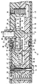
- the gear train 11 of the radio-controlled wristwatch movement 12 is completely functional in itself in a two-part, not necessarily box-shaped closed gear block 13 from each other and parallel to the wheels, profiled work and Carrier plates 14, 15 arranged. They are not necessarily stepless along one a level dividing line 16, saving a gear space 17 by means of at least one bridging the dividing joints 16 and rearward in the support plate 15 countersunk head clamping screw 18 parallel to the work axis 19 clamped together.
- the minute shaft 20 is in a, journal bearing 21 in the Carrier plate 15 held and opposite from which the minute wave 20th concentrically surrounding hour tube 22 radially guided, which in turn has a central bore 23 protrudes in the work plate 14 and is rotatably supported radially therein.
- the hour tube 22 is axially supported within the transmission space 17 by means of the hour wheel 22 molded or attached to the hour tube 22 24, on the one hand on the back 25 of the work plate 14 and on the other hand on the front end face 26 of a pinion 27 formed on the minute shaft 20 is supported.
- the torque transmission from the minute shaft pinion 27 to the hour wheel 24 takes place by means of a change gear including change gear pinion, which in the drawing are not shown because their axis offset parallel to the pointer shaft axis 19 lies outside the longitudinal sectional plane shown in the drawing.
- This is between a front and a rear journal bearing 31, 32 in the work plate 14 or held in the carrier plate 15 and equipped with an intermediate wheel 33, which with the (outside this cutting plane and therefore not shown) rotor pinion 34 of a stepper motor 35 driven in a time-keeping manner combs, which is arranged on the main circuit board 43 and with its pinion 34 in 113 protrudes.
- the transmitter 37 a semiconductor diode with radiation in the visible or invisible spectrum, preferably in the near infrared spectrum, is mechanically held in front of the work plate opening 36.4 by means of an auxiliary circuit board 41, projecting somewhat into it.
- the light barrier receiver 38 which is matched to that radiation spectrum, is arranged on the front or component side 42 of the main circuit board 43 located behind the carrier plate 15, projecting into a carrier plate opening 36.5.
- the mechanical connection of the two circuit boards 41, 43 with the gear block 13 and the electrical connection of the two circuit boards 41-43 to one another takes place - with simultaneous additional bracing of work plate 14 and carrier plate 15 with each other - on both sides of the gear block 13 by means of a electrically conductive (metal or electrically conductive coated) anchor screw 44.
- Their threaded shaft 45 engages in an internally threaded pillar 46, which is stored in the auxiliary circuit board 41 and in the exemplary embodiment on the latter front liner 47 is placed, for example soldered, so that the latter electrically via the anchor screw head 48 with the rear conductor track lamination 49 of the main circuit board 43 is electrically connected.
- Axially parallel Akerschraub channel 50 extends parallel in close proximity a guide channel through the work plate 14 and the support plate 15 51 for a pressure contact spring 52 (preferably as outlined a coil spring) which are located on the front lamination 53 of the main printed circuit board 43 and supports forward on the back 54 of the auxiliary circuit board 41, here opposite whose backing 47 is isolated.
- a pressure contact spring 52 preferably as outlined a coil spring
- the spring 52 against the auxiliary circuit board 41 ends with a metallized access 55, via which the electrically conductive spring 52 is connected to the front liner 56 which is thus via the spring 52 to the front liner 53 of the Main circuit board 43 leads.
- Auxiliary circuit board 41 only the mechanical bracket and the electrical connection of the front component of the light barrier 39 (here an unhoused light-emitting diode serves as the radiation transmitter 37) is for this module connected to the main circuit board 43 by means of the anchor screw 44 the lowest possible height in the direction of the pointer shaft and movement axis 19 to strive for. This is achieved in that the radiation transmitter 37 in a Opening 60 of the auxiliary circuit board 41 is recessed and therein on the rear Lamination 56 or one connected to this and the opening 60 bridging metal foil 61 rests, namely mechanically and electrically connected to it.
- the LED chip hardly protrudes over the back one Lamination 47 of the auxiliary circuit board 41 in front and can therefore by means of a bond wire 62 in a relatively flat curve, so not very bulky, to the rear lamination 47 of the auxiliary circuit board 41 are electrically connected. Accordingly, the radiation-impermeable encapsulation 63 is not very thick and the concentration of the potting compound in the vicinity of the radiation transmitter 37, that is to say in the receiving opening 60, reduces the required casting compound and the potting area to about a third compared to potting one Chip component mounted and bonded flat on a surface.
- Adjustment pin 65 can be used as an assembly aid.
- the aperture holes 40 when inserting the idler shaft 64, the minute wave 20 and the hour tube 22 in the carrier plate 15 in succession pushed onto the adjusting pin 65, so that for the light barrier function relevant wheels are already exactly positioned when the gear block 13 by placing the work plate 14 on the support plate 15 and bracing by means of the screw 18 is closed.
- the assembly adjustment pin 65 can now again from the carrier plate opening 36.5 can be removed and then put on the back of the electronic module main circuit board 43 immerse the light barrier receiver 38 to let. Furthermore, the auxiliary circuit board 41 with its radiation transmitter 37 under the Levels of the dial 57 inserted into the front depression 59 of the work plate 14 and mechanically and electrically via the anchor screw 44 to the opposite one Main circuit board 43 connected with the interposition of contact spring 52, the pinion 34 from the stepper motor 35 mounted on the main circuit board 43 combed into the teeth of the idler gear.
- Radio clock movement 12 thus arises if, according to the invention, the gear train 11 functional between work plate 14 and support plate 15 with each other a screw 18 clamped and inserted adjusted with respect to the light barrier 39 to subsequently rearward the electronic module main circuit board 43 by immersing the stepper motor pinion 34 in the toothing of the idler gear 33 and on the front an auxiliary circuit board 41 for the light barrier transmitter 37 to put on the functionally closed gear block 13 and mechanically and electrically conductive by means of an anchor screw 44 axially parallel to the gear block 13 to connect outstandingly, with the interposition of one between the two circuit boards 41-43 clamped contact spring 52.
- the front under the level of the dial 57 lying auxiliary circuit board 41 for the radiation transmitter 37 of the light barrier 39 applies particularly little if it is on a conductive Lamination 56 or film 61 is placed, which has a circuit board opening 60 bridged on the front, with electrical connection to the opposite PCB lamination 47 by means of a bonding wire 63 in particular flat arch and with a correspondingly flat casting hill 63 because of the overall height the radiation transmitter 37 hardly exceeds the thickness of the auxiliary printed circuit board 41, the radiation-permeable encapsulation 63 slightly in the work plate opening 36.4 can protrude.
Landscapes
- Physics & Mathematics (AREA)
- General Physics & Mathematics (AREA)
- Electromechanical Clocks (AREA)
- Electric Clocks (AREA)
- Input Circuits Of Receivers And Coupling Of Receivers And Audio Equipment (AREA)
- Radio Relay Systems (AREA)
- Road Signs Or Road Markings (AREA)
Abstract
Description

Claims (10)
- Funkuhr-Werk (12), insbesondere Funkarmbanduhr-Werk (12), mit einem Räderwerk (11) für eine Zeiger-Zeitanzeige vor einem Zifferblatt (57) und mit einer quer zum Räderwerk (11) orientierten Lichtschranke (39) zur Detektion wenigstens einer definierten Stellung des Räderwerks (11), wofür Räder (Zwischenrad 33, Minutenrad 29, Stundenrad 24) des Räderwerkes (11) mit Blendenöffnungen (40) in die Lichtschranke (39) hineinragen, von der wenigstens ein Element (Strahlungssender 37, Strahlungsempfänger 38) auf wenigstens einer parallel zum Räderwerk (11) angeordneten Leiterplatte (41; 43) angeordnet ist,
dadurch gekennzeichnet,
daß ein Element (Strahlungssender 37) der Lichtschranke (39) in einer Leiterplatten-Durchbrechung (60) elektrisch leitend auf einer diese überbrückenden Leiterebene (Kaschierung 56 oder Folie 61) angeordnet und an eine bezüglich der Leiterplatte (41) gegenüberliegende Kaschierung (47) mittels eines Bonddrahtes (62) elektrisch angeschlossen ist. - Funkuhrwerk nach Anspruch 1,
dadurch gekennzeichnet,
daß die Umgebung des Elementes in der Durchbrechung (60) mit einer strahlungsdurchlässigen Masse (Verguß 63) aufgefüllt ist, die sich bis über den Bogen des Bonddrahtes (62) und über die unmittelbare Nachbarschaft des Randes der Durchbrechung (60) erstreckt. - Funkuhrwerk nach Anspruch 1 oder 2,
dadurch gekennzeichnet,
daß das gegenüberliegende Element (Strahlungsempfänger 38) der Lichtschranke (39) auf der Hauptleiterplatte (43) des Elektronikmoduls des Werkes (12) angeordnet ist und seitlich frei in eine Trägerplatten-Durchbrechung (36.5) hineinragt. - Funkuhrwerk nach einem der vorangehenden Ansprüche,
dadurch gekennzeichnet,
daß die beiden Leiterplatten (Hilfsleiterplatte 41 und Hauptleiterplatte 43) für Strahlungssender (37) und Strahlungsempfänger (38) der Lichtschranke (39) parallel zum Räderwerk (11) mittels einer Ankerschraube (44) auf dessen Getriebeblock (13) außen aufgespannt sind, die zugleich eine elektrische Verbindung von einer Kaschierung (47) der einen Leiterplatte (Hilfsleiterplatte 41) zu einer Kaschierung (49) der anderen Leiterplatte (Hauptleiterplatte 43) herstellt. - Funkuhrwerk nach einem der vorangehenden Ansprüche,
dadurch gekennzeichnet,
daß die beiden Leiterplatten (Hilfsleiterplatte 41 und Hauptleiterplatte 43) für die beiden Elemente (Strahlungssender 37 und Strahlungsempfänger 38) der Lichtschranke (39) unter Zwischenlage des Getriebeblocks (13) für das Räderwerk (11) mittels einer Ankerschraube (44) miteinander mechanisch verspannt sind, parallel zu welcher sich eine Kontakt-Feder (52) für die Verbindung einer Kaschierung (56) der einen Leiterplatte (Hilfsleiterplatte 41) zu einer Kaschierung (53) der anderen Leiterplatte (Hauptleiterplatte 43) erstreckt. - Funkuhrwerk nach Anspruch 5,
dadurch gekennzeichnet,
daß über die Kontakt-Feder (52) und einen elektrisch leitenden Durchstieg (45) die vordere Kaschierung (56) der vorderen Leiterplatte (Hilfsleiterplatte 41) mit der vorderen Kaschierung (53) der rückwärtigen Leiterplatte (Hauptleiterplatte 43) elektrisch verbunden ist. - Funkuhrwerk nach einem der vorangehenden Ansprüche,
dadurch gekennzeichnet,
daß ein Justierstift (65) anstelle eines Elementes (Strahlungssender 37 oder Strahlungsempfänger 38) der Lichtschranke (39) als Richtmittel für die mit der Lichtschranke (39) fluchtenden Räder-Blendenöffnungen (40) bei der Bestückung des Getriebeblocks (13) in dessen Trägerplatte (15) vorgesehen ist, ehe der durch axiales Verspannen von Werkplatte (14) und Trägerplatte (15) miteinander mittels einer Spannschraube (18) geschlossen und der Justierstift (65) durch die Lichtschranken-Elemete auf den der beiderseits auf den Getriebeblock (13) aufgelegten Leiterplatten (41, 43) ersetzt wird. - Funkuhrwerk nach einem der vorangehenden Ansprüche,
dadurch gekennzeichnet,
daß in eine Durchbrechung einer Leiterplatte (Hilfsleiterplatte 41) ein elektrisch leitender Pfeiler (46) eingesteckt ist, der mit einer Leiterplatten-Kaschierung (47) elektrisch verbunden ist und elektrisch leitend die Ankerschraube (44) aufnimmt. - Funkuhrwerk nach einem der vorangehenden Ansprüche,
dadurch gekennzeichnet,
daß der von einer Leiterplatte (Hauptleiterplatte 43) getragene Schrittmotor (35) mit seinem Ritzel (34) mit dem Zwischenrad (33) kämmend in den Getrieberaum (17) des Getriebeblocks (13) eingreift, wenn der mit der Leiterplatte (43) belegt wird. - Verfahren zum Montieren eines Funkuhrwerkes gemäß einem der vorangehenden Ansprüche,
dadurch gekennzeichnet,
daß in der Lichtschrankendurchbrechung (36.5) der Trägerplatte (15) ein die Lichtschranke (39) repräsentierender Justierstift (65) angeordnet wird, während nacheinander die Zwischenradwelle (64) und die Minutenwelle (20) in ihre Zapfenlager (32, 21) in der Trägerplatte (15) eingesetzt und dabei mit den Blendenöffnungen (40) ihrer Räder (33, 29) über den Justierstift (65) gestülpt werden, mit abschließendem Aufsetzen des Stundenrohres (22) auf die Minutenwelle (20) und Einfädeln der Blendenöffnung (40) des Stundenrades (24) ebenfalls auf den Justierstift (65), ehe der so bestückte Getrieberaum (17) durch Aufsetzen der Werkplatte (14) verschlossen und die beiden Platten (Werkplatte 14 und Trägerplatte 15) mittels einer zur Räderwerks-Achse (19) parallelen Schraube (18) miteinander verspannt werden, woraufhin der Justierstift (65) wieder aus der Trägerplatten-Durchbrechung (36.5) herausgenommen und stattdessen hier ein Lichtschranken-Element (Strahlungsempfänger 38) eingesenkt wird, indem seine Leiterplatte (Hauptleiterplatte 43) rückwärtig gegen die Trägerplatte (15) angelegt und mittels einer Ankerschraube (44) mit einer vorne auf die Werkplatte (14) gelegten Leiterplatte (Hilfsleiterplatte 41) verspannt wird, in der das andere Lichtschrankenelement (Strahlungssender 37) angeordnet ist und in eine Werkplatten-Durchbrechung (36.4) hineinragt, unter Zwischenlage einer in einem Kanal (51) durch Werkplatte (14) und Trägerplatte (15) hindurch geführten Kontaktfeder (52) zwischen die beiden Leiterplatten (41-43).
Applications Claiming Priority (2)
| Application Number | Priority Date | Filing Date | Title |
|---|---|---|---|
| DE29714186U DE29714186U1 (de) | 1997-08-08 | 1997-08-08 | Funkuhrwerk |
| DE29714186U | 1997-08-08 |
Publications (2)
| Publication Number | Publication Date |
|---|---|
| EP0899636A1 true EP0899636A1 (de) | 1999-03-03 |
| EP0899636B1 EP0899636B1 (de) | 2002-04-03 |
Family
ID=8044348
Family Applications (1)
| Application Number | Title | Priority Date | Filing Date |
|---|---|---|---|
| EP98114625A Expired - Lifetime EP0899636B1 (de) | 1997-08-08 | 1998-08-04 | Funkuhrwerk |
Country Status (5)
| Country | Link |
|---|---|
| US (1) | US5898644A (de) |
| EP (1) | EP0899636B1 (de) |
| JP (1) | JP3955391B2 (de) |
| AT (1) | ATE215710T1 (de) |
| DE (2) | DE29714186U1 (de) |
Families Citing this family (17)
| Publication number | Priority date | Publication date | Assignee | Title |
|---|---|---|---|---|
| EP0952426B1 (de) * | 1998-04-24 | 2003-09-03 | Asulab S.A. | Uhrwerk mit einem induktiven oder kapazitiven Sensor zur Detektion von mindestens einem Drehwinkel eines Zahnrades innerhalb des Uhrwerkes |
| SG85647A1 (en) * | 1998-06-29 | 2002-01-15 | Asulab Sa | Device including at least two coaxial wheels and means for detecting the angular position thereof and method for detecting said angular positions |
| US6356512B1 (en) * | 1998-07-20 | 2002-03-12 | Asulab S.A. | Subassembly combining an antenna and position sensors on a same support, notably for a horological piece |
| CN1132077C (zh) * | 1999-05-06 | 2003-12-24 | 阿苏拉布股份有限公司 | 包括用于指示同轴模拟显示指针之角度位置的装置的钟表 |
| US6473367B2 (en) * | 2000-12-15 | 2002-10-29 | Koung-Chung Peng | Positioning mechanism for a radio clock |
| US6473366B2 (en) * | 2000-12-15 | 2002-10-29 | Koung-Chung Peng | Method for timing a clock |
| US20030063525A1 (en) * | 2001-09-28 | 2003-04-03 | Ken Richardson | Microprocessor controlled quartz analog clock movement |
| JP2003227884A (ja) * | 2001-11-29 | 2003-08-15 | Casio Comput Co Ltd | 発光表示装置及び電子機器 |
| EP1357448A1 (de) * | 2002-04-26 | 2003-10-29 | Kienzle Time (Hong Kong) Limited | Funkgesteuerte Uhr |
| ITPD20020264A1 (it) * | 2002-10-15 | 2004-04-16 | Geox Spa | Suola impermeabilizzata e traspirante perfezionata per calzature e suo procedimento di realizzazione. |
| US20040085860A1 (en) * | 2002-10-31 | 2004-05-06 | Yiu Chih Hao | Position detecting and correcting device for timepiece |
| US20040120223A1 (en) * | 2002-12-20 | 2004-06-24 | Luk Tai Wai | Timepiece movement |
| EP1607808B1 (de) * | 2004-06-15 | 2010-08-25 | Asulab S.A. | Verfahren zur Synchronisierung der analogen Anzeige einer Uhr mit einem elektronischen Taktgeber |
| JP2010122157A (ja) * | 2008-11-21 | 2010-06-03 | Casio Computer Co Ltd | 指針機器 |
| JP2010122156A (ja) * | 2008-11-21 | 2010-06-03 | Casio Computer Co Ltd | 指針機器 |
| JP2010230509A (ja) * | 2009-03-27 | 2010-10-14 | Citizen Holdings Co Ltd | 指針位置機能付き電子時計 |
| CH707787B1 (fr) * | 2013-03-25 | 2021-09-15 | Richemont Int Sa | Organe régulateur pour montre bracelet et procédé d'assemblage d'un organe régulateur pour montre bracelet. |
Citations (6)
| Publication number | Priority date | Publication date | Assignee | Title |
|---|---|---|---|---|
| GB2032656A (en) * | 1978-09-22 | 1980-05-08 | Citizen Watch Co Ltd | Electronic watch module construction |
| CH638947GA3 (en) * | 1977-06-23 | 1983-10-31 | Circuit for electronic timepiece, especially for an electronic wristwatch | |
| US4555184A (en) * | 1982-12-07 | 1985-11-26 | Shiojiri Kogyo Kabushiki Kaisha | Module for combination timepiece |
| EP0180880A2 (de) * | 1984-11-09 | 1986-05-14 | Junghans Uhren Gmbh | Anzeigestellungs-Detektionseinrichtung für eine Uhr, insbesondere eine Funkuhr |
| US4742432A (en) * | 1984-12-07 | 1988-05-03 | U.S. Philips Corporation | Matrix of light-emitting elements and method of manufacturing same |
| FR2639727A1 (fr) * | 1988-11-30 | 1990-06-01 | Ruhla Uhren Veb K | Mecanisme d'horlogerie pour montres a commande radio |
Family Cites Families (2)
| Publication number | Priority date | Publication date | Assignee | Title |
|---|---|---|---|---|
| DE4128752C2 (de) * | 1991-08-29 | 1997-12-04 | Junghans Uhren Gmbh | Stellungsdetektions- und -Korrektureinrichtung |
| JP2500513B2 (ja) * | 1992-11-10 | 1996-05-29 | 株式会社精工舎 | 時計機械体 |
-
1997
- 1997-08-08 DE DE29714186U patent/DE29714186U1/de not_active Expired - Lifetime
-
1998
- 1998-06-22 JP JP17476198A patent/JP3955391B2/ja not_active Expired - Fee Related
- 1998-07-21 US US09/119,578 patent/US5898644A/en not_active Expired - Lifetime
- 1998-08-04 EP EP98114625A patent/EP0899636B1/de not_active Expired - Lifetime
- 1998-08-04 DE DE59803590T patent/DE59803590D1/de not_active Expired - Lifetime
- 1998-08-04 AT AT98114625T patent/ATE215710T1/de not_active IP Right Cessation
Patent Citations (6)
| Publication number | Priority date | Publication date | Assignee | Title |
|---|---|---|---|---|
| CH638947GA3 (en) * | 1977-06-23 | 1983-10-31 | Circuit for electronic timepiece, especially for an electronic wristwatch | |
| GB2032656A (en) * | 1978-09-22 | 1980-05-08 | Citizen Watch Co Ltd | Electronic watch module construction |
| US4555184A (en) * | 1982-12-07 | 1985-11-26 | Shiojiri Kogyo Kabushiki Kaisha | Module for combination timepiece |
| EP0180880A2 (de) * | 1984-11-09 | 1986-05-14 | Junghans Uhren Gmbh | Anzeigestellungs-Detektionseinrichtung für eine Uhr, insbesondere eine Funkuhr |
| US4742432A (en) * | 1984-12-07 | 1988-05-03 | U.S. Philips Corporation | Matrix of light-emitting elements and method of manufacturing same |
| FR2639727A1 (fr) * | 1988-11-30 | 1990-06-01 | Ruhla Uhren Veb K | Mecanisme d'horlogerie pour montres a commande radio |
Also Published As
| Publication number | Publication date |
|---|---|
| JP3955391B2 (ja) | 2007-08-08 |
| HK1017931A1 (en) | 1999-12-03 |
| DE29714186U1 (de) | 1998-12-10 |
| US5898644A (en) | 1999-04-27 |
| DE59803590D1 (de) | 2002-05-08 |
| JPH1194955A (ja) | 1999-04-09 |
| ATE215710T1 (de) | 2002-04-15 |
| EP0899636B1 (de) | 2002-04-03 |
Similar Documents
| Publication | Publication Date | Title |
|---|---|---|
| EP0899636B1 (de) | Funkuhrwerk | |
| DE4337390C3 (de) | Antriebseinheit für Verstellsysteme in Kraftfahrzeugen | |
| EP0474904B1 (de) | Kommutator-Getriebe-Antriebseinheit, insbesondere Fensterheberantrieb für ein Kraftfahrzeug, und Verfahren zu deren Herstellung | |
| DE3206155C2 (de) | ||
| EP1969626A1 (de) | Elektronikmodul sowie verfahren zur herstellung eines solchen | |
| EP0253225A2 (de) | Verfahren zum Bestücken eines Leiterbahnen-Netzwerks für den Schaltungsträger eines elektromechanischen Uhrwerks und teilbestücktes Leiterbahnen-Netzwerk eines Uhrwerks-Schaltungsträgers | |
| EP1228285B1 (de) | Elektronische steuerungseinrichtung zur ansteuerung elektrischer aggregate von kraftfahrzeugtüren mit unterschiedlicher ausstattung | |
| EP0531853A2 (de) | Funkuhr-Werk | |
| DE102015122095A1 (de) | Anschlusseinheit für einen Wischermotor für Scheibenwischanlagen und Wischermotor | |
| WO2002070921A1 (de) | Mechatronische getriebesteuerung | |
| EP1324475A2 (de) | Motor-Sensor-System | |
| DE10332167A1 (de) | Encodersystem und Verfahren zur Montage eines Encodersystems | |
| DE102015211147A1 (de) | Antriebseinheit | |
| DE2839555B2 (de) | Elektromechanische Antriebsanordnung in einem kleinen Gerät und Verfahren zum Zusammenbau einer solchen Antriebsanordnung in dem Gerät | |
| WO2024188973A1 (de) | Leiterplattenbaugruppe für eine antriebseinheit eines elektrofahrrads und montageverfahren | |
| DE19858232C1 (de) | Elektrische Antriebseinheit für Fahrzeugaggregate | |
| DE102008053036A1 (de) | Antriebsbaugruppe für die motorische Verstellung eines Verstellelements in einem Kraftfahrzeug | |
| DE3047492C2 (de) | ||
| DE2620861C2 (de) | Elektronische Uhr | |
| EP3256820B1 (de) | Getriebesteuermodul | |
| EP1707440A2 (de) | Befestigung elektronischer Bauteile im Bereich der Windschutzscheibe eines Fahrzeuges | |
| DE2342544A1 (de) | Elektrische uhr | |
| WO2010025979A1 (de) | Generatormodul und verfahren zur herstellung eines generatormoduls | |
| DE19980533B4 (de) | Abschirmung einer auf einem metallischen Substrat angebrachten elektronischen Karte mit gedruckter Schaltung | |
| DE2839611C2 (de) | Verfahren zum Bestücken einer Leiterplatte für ein batteriebetriebenes Gerät mit einem Motor, insbesondere einer Uhr |
Legal Events
| Date | Code | Title | Description |
|---|---|---|---|
| PUAI | Public reference made under article 153(3) epc to a published international application that has entered the european phase |
Free format text: ORIGINAL CODE: 0009012 |
|
| 17P | Request for examination filed |
Effective date: 19981219 |
|
| AK | Designated contracting states |
Kind code of ref document: A1 Designated state(s): AT CH DE FR GB IT LI |
|
| AX | Request for extension of the european patent |
Free format text: AL;LT;LV;MK;RO;SI |
|
| AKX | Designation fees paid |
Free format text: AT CH DE FR GB IT LI |
|
| GRAG | Despatch of communication of intention to grant |
Free format text: ORIGINAL CODE: EPIDOS AGRA |
|
| 17Q | First examination report despatched |
Effective date: 20010807 |
|
| GRAG | Despatch of communication of intention to grant |
Free format text: ORIGINAL CODE: EPIDOS AGRA |
|
| GRAH | Despatch of communication of intention to grant a patent |
Free format text: ORIGINAL CODE: EPIDOS IGRA |
|
| GRAH | Despatch of communication of intention to grant a patent |
Free format text: ORIGINAL CODE: EPIDOS IGRA |
|
| REG | Reference to a national code |
Ref country code: GB Ref legal event code: IF02 |
|
| GRAA | (expected) grant |
Free format text: ORIGINAL CODE: 0009210 |
|
| AK | Designated contracting states |
Kind code of ref document: B1 Designated state(s): AT CH DE FR GB IT LI |
|
| REF | Corresponds to: |
Ref document number: 215710 Country of ref document: AT Date of ref document: 20020415 Kind code of ref document: T |
|
| REG | Reference to a national code |
Ref country code: CH Ref legal event code: EP |
|
| REG | Reference to a national code |
Ref country code: CH Ref legal event code: NV Representative=s name: A. BRAUN, BRAUN, HERITIER, ESCHMANN AG PATENTANWAE |
|
| REF | Corresponds to: |
Ref document number: 59803590 Country of ref document: DE Date of ref document: 20020508 |
|
| GBT | Gb: translation of ep patent filed (gb section 77(6)(a)/1977) |
Effective date: 20020618 |
|
| ET | Fr: translation filed | ||
| PLBE | No opposition filed within time limit |
Free format text: ORIGINAL CODE: 0009261 |
|
| STAA | Information on the status of an ep patent application or granted ep patent |
Free format text: STATUS: NO OPPOSITION FILED WITHIN TIME LIMIT |
|
| 26N | No opposition filed |
Effective date: 20030106 |
|
| PGFP | Annual fee paid to national office [announced via postgrant information from national office to epo] |
Ref country code: AT Payment date: 20070822 Year of fee payment: 10 |
|
| PGFP | Annual fee paid to national office [announced via postgrant information from national office to epo] |
Ref country code: GB Payment date: 20070828 Year of fee payment: 10 |
|
| PGFP | Annual fee paid to national office [announced via postgrant information from national office to epo] |
Ref country code: IT Payment date: 20070828 Year of fee payment: 10 |
|
| REG | Reference to a national code |
Ref country code: CH Ref legal event code: PFA Owner name: JUNGHANS UHREN GMBH Free format text: JUNGHANS UHREN GMBH#GEISSHALDENSTRASSE 49#78713 SCHRAMBERG (DE) -TRANSFER TO- JUNGHANS UHREN GMBH#GEISSHALDENSTRASSE 49#78713 SCHRAMBERG (DE) |
|
| GBPC | Gb: european patent ceased through non-payment of renewal fee |
Effective date: 20080804 |
|
| PG25 | Lapsed in a contracting state [announced via postgrant information from national office to epo] |
Ref country code: AT Free format text: LAPSE BECAUSE OF NON-PAYMENT OF DUE FEES Effective date: 20080804 |
|
| PG25 | Lapsed in a contracting state [announced via postgrant information from national office to epo] |
Ref country code: IT Free format text: LAPSE BECAUSE OF NON-PAYMENT OF DUE FEES Effective date: 20080804 |
|
| PG25 | Lapsed in a contracting state [announced via postgrant information from national office to epo] |
Ref country code: GB Free format text: LAPSE BECAUSE OF NON-PAYMENT OF DUE FEES Effective date: 20080804 |
|
| PGFP | Annual fee paid to national office [announced via postgrant information from national office to epo] |
Ref country code: FR Payment date: 20110829 Year of fee payment: 14 |
|
| REG | Reference to a national code |
Ref country code: FR Ref legal event code: ST Effective date: 20130430 |
|
| PG25 | Lapsed in a contracting state [announced via postgrant information from national office to epo] |
Ref country code: FR Free format text: LAPSE BECAUSE OF NON-PAYMENT OF DUE FEES Effective date: 20120831 |
|
| REG | Reference to a national code |
Ref country code: CH Ref legal event code: PCAR Free format text: NEW ADDRESS: HOLBEINSTRASSE 36-38, 4051 BASEL (CH) |
|
| PGFP | Annual fee paid to national office [announced via postgrant information from national office to epo] |
Ref country code: CH Payment date: 20140821 Year of fee payment: 17 |
|
| REG | Reference to a national code |
Ref country code: DE Ref legal event code: R082 Ref document number: 59803590 Country of ref document: DE Representative=s name: PATENTANWAELTE WESTPHAL MUSSGNUG & PARTNER, DE |
|
| REG | Reference to a national code |
Ref country code: DE Ref legal event code: R082 Ref document number: 59803590 Country of ref document: DE Representative=s name: WESTPHAL, MUSSGNUG & PARTNER PATENTANWAELTE MI, DE Effective date: 20150123 Ref country code: DE Ref legal event code: R081 Ref document number: 59803590 Country of ref document: DE Owner name: UHRENFABRIK JUNGHANS GMBH & CO. KG, DE Free format text: FORMER OWNER: JUNGHANS UHREN GMBH, 78713 SCHRAMBERG, DE Effective date: 20150123 |
|
| REG | Reference to a national code |
Ref country code: CH Ref legal event code: PL |
|
| PG25 | Lapsed in a contracting state [announced via postgrant information from national office to epo] |
Ref country code: LI Free format text: LAPSE BECAUSE OF NON-PAYMENT OF DUE FEES Effective date: 20150831 Ref country code: CH Free format text: LAPSE BECAUSE OF NON-PAYMENT OF DUE FEES Effective date: 20150831 |
|
| PGFP | Annual fee paid to national office [announced via postgrant information from national office to epo] |
Ref country code: DE Payment date: 20170928 Year of fee payment: 20 |
|
| REG | Reference to a national code |
Ref country code: DE Ref legal event code: R071 Ref document number: 59803590 Country of ref document: DE |