EP0899701A2 - Détecteur sélectif de mouvement et de direction - Google Patents
Détecteur sélectif de mouvement et de direction Download PDFInfo
- Publication number
- EP0899701A2 EP0899701A2 EP98111593A EP98111593A EP0899701A2 EP 0899701 A2 EP0899701 A2 EP 0899701A2 EP 98111593 A EP98111593 A EP 98111593A EP 98111593 A EP98111593 A EP 98111593A EP 0899701 A2 EP0899701 A2 EP 0899701A2
- Authority
- EP
- European Patent Office
- Prior art keywords
- detection system
- motion detector
- detection
- detector according
- sensor
- Prior art date
- Legal status (The legal status is an assumption and is not a legal conclusion. Google has not performed a legal analysis and makes no representation as to the accuracy of the status listed.)
- Withdrawn
Links
Images


Classifications
-
- G—PHYSICS
- G08—SIGNALLING
- G08B—SIGNALLING SYSTEMS, e.g. PERSONAL CALLING SYSTEMS; ORDER TELEGRAPHS; ALARM SYSTEMS
- G08B13/00—Burglar, theft or intruder alarms
- G08B13/18—Actuation by interference with heat, light, or radiation of shorter wavelength; Actuation by intruding sources of heat, light, or radiation of shorter wavelength
- G08B13/189—Actuation by interference with heat, light, or radiation of shorter wavelength; Actuation by intruding sources of heat, light, or radiation of shorter wavelength using passive radiation detection systems
- G08B13/19—Actuation by interference with heat, light, or radiation of shorter wavelength; Actuation by intruding sources of heat, light, or radiation of shorter wavelength using passive radiation detection systems using infrared-radiation detection systems
- G08B13/193—Actuation by interference with heat, light, or radiation of shorter wavelength; Actuation by intruding sources of heat, light, or radiation of shorter wavelength using passive radiation detection systems using infrared-radiation detection systems using focusing means
Definitions
- the invention relates to a motion detector for movement and direction selective Detection of moving objects emitting heat radiation, especially of people.
- Such a motion detector is described in DE 36 13 374 A1.
- the one out of it known pyrodetector has wide-angle properties in mainly one plane. It has a spherical to spherical-parabolic mirror, in which one Sensor array arranged on a pyroelectric film is located with a large number of sensor elements. One is from signal differences of the sensor elements Direction of a detected object can be derived.
- the wide-angle properties of the fest mounted motion detectors are practically limited to approximately ⁇ 60 °.
- the achievable Direction selectivity is not for despite the high implementation effort required all uses are sufficient.
- known motion detectors sometimes have a wider detection angle and are suitable for controlling permanently installed lighting devices.
- the lighting device is switched on as soon as a moving object is detected in the detection area
- the location of the heat-radiating object and its direction of movement cannot be detected with these motion detectors
- the range and sensitivity of such motion detectors are often limited by suitable measures in order to avoid false triggering.
- the invention has for its object to provide a motion detector Detect an object in a wide detection area and its direction of movement recognize and follow her.
- the Motion detector a light cone of a light source directed at the object and the Object to be trackable.
- the motion detector works with two detection systems, one immobile Detection system and a movable detection system. Output signals both systems are detected by a control device.
- the first registration system enables rough direction detection, the second detection system one Tracking a detected object with high accuracy of location.
- An electrical drive for moving the second detection system becomes dependent controlled by measurement signals from both detection systems.
- a Headlights or directional spotlights coupled to the electric drive the Headlights controlled by the motion detector on a detected object is judgable.
- the second detection system and the headlights connected to it are rotatable at least about a vertical axis.
- you can Means are present that have a variable inclination of the second detection system and / or the headlight.
- the motion detector according to the invention has a number of advantages. Depending on Execution, in particular depending on the number of detection modules arranged of the first detection system and depending on the installation location, e.g. Arrangement on one Mast, a detection angle of up to 360 ° can be achieved. Through a two-stage object detection by means of the two detection systems there is increased security against false triggering. If a headlight with the motion detector is coupled, a light cone can be aimed at a detected person and be tracked. The motion detector can also be used for the Determine the speed of movement of an object and derive measures from it.
- FIG. 1 shows a basic illustration of a preferred embodiment of a motion detector, which is mounted on a building wall 9.
- Essential components of the motion detector are a first, immobile detection system 1, a second, movable detection system 6, a rotatable bracket 4 with headlights 5, and a control device 8.
- the second detection system 6 and the headlight arrangement 4, 5 are by means of of an electric drive 15 (FIG. 2), which is preferably in the first detection system 1 is arranged, mechanically coupled to each other and around a vertical Axis A can be rotated.
- a stepper motor for example, is used as the drive motor suitable.
- the first detection system 1 which is also shown in FIG. 2 in a top view is a permanently activated object space monitoring system that composed of several modules 2.
- a module 2 is compensated by a constant light Dual sensor 10 (Fig. 2) and an upstream multi-lens optics 3 formed.
- the multi-lens optics 3 can have several, e.g. two lines 31 with for example have six individual Fresnel lens segments 32.
- a module 2 can e.g. be designed for an opening angle 11 of 60 °. With six individual segments 32 creates a sensitive imaging cone 33 at a distance of 10 °.
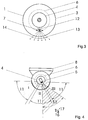
- the second detection system 6 shows in connection with FIG. 3 (top view) the second detection system 6, this is only temporary, namely after detection of an object by the first detection system 1 is activated by the control device 8. It contains a multi-element sensor 12 with an upstream lens optics 7.
- the multi-element sensor 12 can be a line or array sensor. A large single frensel lens is used as lens optics 7 or a conventional large lens.
- the optics 7 and the Multi-element sensor 12 are arranged rigidly to one another.
- the one by arrangement Specified total opening angle 13 of the second detection system 6 can for example are at 60 °, that is to say the same size as the opening angle 11 of one Module 2 of the first detection system 1.
- FIG. 6, in addition to FIG. 3, makes it clear that the combination of a multi-element sensor 12 with a single lens 7 causes that by imaging the individual Sensor elements 121 each element has its own observation lobe through the lens 14 is assigned.
- a desired focal length and the sensor geometry a desired club density can be realized. It can be a fine one Resolution of, for example, 10 ° can be achieved with the direction of a moving Object can be determined exactly. This resolution is not to be confused with the exemplary 10 ° distance of the imaging cone of the multi-lens optics 3; because there it is only detected by means of the imaging cone whether an object moves in the area of the module opening angle 11.
- the individual lens 7 can be designed with a significantly larger lens area, than would be possible with a sequence of lens segments of a multi-lens, because in the latter the angular distance between two lens centers is required by the Club density is limited. This is automatically the given focal length Set the width of such segments.
- the club density is only determined by the distance determines the sensor elements of the multi-element sensor 12, for which it is only technological and there are irrelevant limits for the use of motion detectors.
- FIG. 5 shows the headlight or spotlight 5, which is rotated by means of the rotatable holder 4 is connected to the motion detector, and in its horizontal plane of rotation is rigidly connected to the movement of the second detection system. Both with their main axes always pointing in the same direction.
- the headlight 5 can be rotated at least horizontally. In a training course, it can also be vertical be pivotable, especially when using a two-dimensional sensor array in addition to the horizontal angle to determine the direction of observation the vertical object angle and the distance from it can be determined.
- the movable lighting 5 advantageous as this supports the concept of observation in narrow angular ranges and enables a higher illuminance in these.
- the beam angle of the light cone 18 of the movable lighting 5 identical or slightly larger than the opening angle 11 of the modules 2 or of the second detection system 6, e.g. 60 ° to choose. So that is a constant Illumination of the moving object is also possible if it is within the range of module 2 and a tracking of the second acquisition system, and the coupled lighting device 5 required.
- FIG. 4 are a top view of the motion detector and its detection areas the opening angle 11 of three segments designated I, II, III shown are determined by modules 2 of the first detection system 1.
- the opening angle 13 of the second detection system 6 can be parts of two segments, e.g. I and II according to the exact location and direction of movement 17 of an object or a person 16, cover.
- an object is detected by one of the modules 2 of the first detection system 1, that is, if a sensor signal is generated above a predetermined threshold value, then in a first reaction stage of the system, one assigned to the respective module 2 ID number of the control device 8 communicated.
- the control device 8 is activated the second detection system 6 for checking the detection and for determination the exact direction in which the object 16 is located.
- the device's own radiator 5 is not yet activated, but one with a Switching output of the control device 8 connected permanently installed lighting system can already be used as basic lighting at this stage be switched on.
- the activated second detection system 6 is controlled by the control device 8 and the drive 15 in the rough direction reported by the first detection system 1 rotated so that the main direction of its detection area 13 with the center of the Opening angle 11 of the corresponding module 2 matches. After graduation of the rotational movement, the second detection system 6 detects the object 16. The individual sensor signals of the multi-element sensor 12 below Using the center of gravity method, the exact direction of the object 16 is determined.
- a second reaction level triggered This means that the headlight 5 is turned on and that second detection system 6 remains activated to the direction of movement and the respective To capture the location of the object.
- the exact from the signals of the individual elements of the multi-element sensor 12 Location can be determined. Only when the object leaves the total angular range 13 does this take place a tracking of the movable second detection system 6 in the middle of the Opening angle 11 of an adjacent segment, e.g. I.
- the second detection system 6 and the headlight 5 are not detected. However, the duration of the movement can be in the millisecond range, so that there is none there is a significant loss of observation time.
- An intermediate position can be used for tracking the second detection system 6 be provided so that e.g. the main optical axis of the second detection system 6 exactly on the boundary between the opening angles 11 of two modules 2 lies.
- the light of the detector's own moving headlight 5 remains during Tracking switched on.
- the headlight 5 itself is with the second detection system 6 carried, which ensures permanent lighting of the object is.
- the observation is in the new position of the second detection system 2 continued as described above. Every single signal acquisition starts one Follow-up time for the lighting that passes until after the last motion signal the light goes out.
- the lighting and also the active observation through the second detection system 6 are then switched off when there is no more signal is received and the adjustable delay time has expired.
- This case occurs two situations one: firstly, the object from the last one through basic modules still covered observation angle, so that another Tracking is not possible, e.g. because a rotation stop at ⁇ 90 ° (in the case of three modules each 60 °) is reached. Or the moving object is within the observed one Area has come to a standstill.
- the preferred location can e.g. a chosen main direction of observation along a driveway, and can be customized on the device. Switching off the second detection system 6 causes only signals from the modules 2 of the first detection system 1 from the control device 8 be accepted. This state is the basic state and remains until the next signal is received by a module 2. Only then does it switch second detection system again in the right direction.
- Borderline situations can also be managed with the motion detector. Becomes for example, two adjacent modules 2 move simultaneously of the module limit, the second detection system 6 switches on and focuses on the area boundary instead of the main direction as usual of the reporting module 2. This ensures tracking.
- a module 2 other than the one that is currently being supplemented by the second detection system delivers a signal.
- either a medium observation and illumination angle can be set as a compromise, and / or a second one Switching signal to connect a global external lighting system to the Given control device.
- the main optical axis of the second detection system can either be horizontal or run slightly inclined to the earth.
- the former has the advantage that there are no geometrical ones Range limitation occurs and the object is recorded in full size.
- the background is thermally very variable, e.g. because of a busy street, this could result in the device no longer switching off. In this case, an inclination of the motion detector is more favorable.
- the control device 8 coordinates the operation of the permanently active first Detection system 1 and the second detection system 6. It generates the Switching signals for the headlamp 5 and any external lights provided. Switching signals could also be generated with which a video camera can be inserted into the detected direction of a moving object is controlled.
- These functions can e.g. B. anyway in most motion detectors for signal processing existing microcontrollers or ASICs.
- you can all other functions common to motion detectors can be implemented, such as for example, querying control elements, signal filtering, threshold value generation, Noise and malfunction suppression, temperature correction, Time delay control and consideration of a response brightness.
- the second detection system 6 Since the second detection system 6 enables the direction of movement and the Determining the speed is also an update of the tracking in a probable direction possible if the detected object is temporarily through an object should be covered.
Landscapes
- Physics & Mathematics (AREA)
- General Physics & Mathematics (AREA)
- Lighting Device Outwards From Vehicle And Optical Signal (AREA)
Applications Claiming Priority (2)
| Application Number | Priority Date | Filing Date | Title |
|---|---|---|---|
| DE1997137761 DE19737761A1 (de) | 1997-08-29 | 1997-08-29 | Bwegungs- und richtungsselektiver Bewegungsmelder |
| DE19737761 | 1997-08-29 |
Publications (2)
| Publication Number | Publication Date |
|---|---|
| EP0899701A2 true EP0899701A2 (fr) | 1999-03-03 |
| EP0899701A3 EP0899701A3 (fr) | 2000-01-12 |
Family
ID=7840615
Family Applications (1)
| Application Number | Title | Priority Date | Filing Date |
|---|---|---|---|
| EP98111593A Withdrawn EP0899701A3 (fr) | 1997-08-29 | 1998-06-24 | Détecteur sélectif de mouvement et de direction |
Country Status (3)
| Country | Link |
|---|---|
| EP (1) | EP0899701A3 (fr) |
| DE (1) | DE19737761A1 (fr) |
| NO (1) | NO983967D0 (fr) |
Cited By (4)
| Publication number | Priority date | Publication date | Assignee | Title |
|---|---|---|---|---|
| EP1184824A1 (fr) * | 2000-09-02 | 2002-03-06 | Siemens Building Technologies AG | Détecteur passif d'infrarouges |
| WO2007147179A1 (fr) * | 2006-06-14 | 2007-12-21 | Gideon Botha | Dispositif de sécurité |
| EP2372238A1 (fr) * | 2010-04-01 | 2011-10-05 | Steinel GmbH | Dispositif d'éclairage commandé par capteur de mouvement et dispositif de capteur de mouvement |
| CN113727604A (zh) * | 2019-03-29 | 2021-11-30 | 威里利生命科学有限责任公司 | 昆虫诱捕系统 |
Families Citing this family (2)
| Publication number | Priority date | Publication date | Assignee | Title |
|---|---|---|---|---|
| DE10251133B3 (de) * | 2002-10-31 | 2004-07-29 | Gerd Reime | Einrichtung zur Steuerung einer Beleuchtung, insbesondere für Fahrzeuginnenräume sowie Verfahren zu ihrer Steuerung |
| DE102006024512A1 (de) * | 2006-05-23 | 2007-11-29 | Judith Gabel | System zur Regelung und Steuerung von Lichtquellen und Beleuchtungseinrichtungen |
Family Cites Families (24)
| Publication number | Priority date | Publication date | Assignee | Title |
|---|---|---|---|---|
| DE2911363A1 (de) * | 1979-03-23 | 1980-09-25 | Inform Ges Fuer Informations U | Ueberwachungseinrichtung |
| US4321594A (en) * | 1979-11-01 | 1982-03-23 | American District Telegraph Company | Passive infrared detector |
| DE3616374A1 (de) * | 1986-05-15 | 1987-11-19 | Siemens Ag | Pyrodetektor, vorzugsweise geeignet fuer bewegungs- und richtungsselektives detektieren |
| DE3713795A1 (de) * | 1987-04-24 | 1988-11-10 | Siemens Ag | Verfahren zum betrieb eines pyrodetektors zur detektion und/oder zur bestimmung der geschwindigkeit eines bewegten objekts |
| DE3803278A1 (de) * | 1988-02-04 | 1989-08-17 | Brueck Electronic Beg Gmbh | Infrarot-signalgeber |
| EP0408980A3 (en) * | 1989-07-17 | 1993-01-07 | Siemens Aktiengesellschaft | Passive infrared movement detector with angular resolution |
| IL91441A0 (en) * | 1989-08-25 | 1990-04-29 | Israel Aircraft Ind Ltd | Forest fire sensing system |
| US5107120A (en) * | 1989-09-22 | 1992-04-21 | Pennwalt Corporation | Passive infrared detector |
| DE3932681C2 (de) * | 1989-09-29 | 2002-03-07 | Siemens Ag | Hochfehlalarmsicheres Objektsicherungssystem mit einer Vielzahl von Passiv-Infrarot-(IR)-Sensoren |
| CH681574A5 (fr) * | 1991-03-01 | 1993-04-15 | Cerberus Ag | |
| JP2550339Y2 (ja) * | 1991-06-03 | 1997-10-08 | 株式会社村田製作所 | 熱源移動検出装置 |
| US5291020A (en) * | 1992-01-07 | 1994-03-01 | Intelectron Products Company | Method and apparatus for detecting direction and speed using PIR sensor |
| DE4220508C2 (de) * | 1992-06-22 | 1998-08-20 | Iris Gmbh Infrared & Intellige | Vorrichtung zur Erfassung von Personen |
| JPH078735U (ja) * | 1993-07-09 | 1995-02-07 | 株式会社村田製作所 | 赤外線センサ装置 |
| DE9314604U1 (de) * | 1993-09-27 | 1993-12-09 | Siemens AG, 80333 München | Infrarot-Bewegungsmelder |
| DE4402535A1 (de) * | 1994-01-28 | 1995-08-03 | Friedrich Brueck | Vorrichtung zur Überwachung von zu sichernden Bereichen |
| US5590953A (en) * | 1995-04-27 | 1997-01-07 | Regent Lighting Corporation | Directable decorative lantern with motion sensor |
| DE19600958A1 (de) * | 1995-07-20 | 1997-01-23 | Fraunhofer Ges Forschung | Interaktives Überwachungssystem |
| US5641963A (en) * | 1995-09-29 | 1997-06-24 | Mueller; Thomas J. | Infrared location system |
| DE19548578C2 (de) * | 1995-12-27 | 2001-02-08 | Elbau Elektronik Bauelemente G | Positionsselektiver passiver Infrarot-Intrusion-Sensor |
| US5729019A (en) * | 1995-12-29 | 1998-03-17 | Honeywell Inc. | Split field-of-view uncooled infrared sensor |
| DE19625235A1 (de) * | 1996-06-24 | 1998-01-02 | Abb Patent Gmbh | Bewegungsmelder zur Detektion von Wärmestrahlung abgebenden, beweglichen Objekten |
| DE29615727U1 (de) * | 1996-09-10 | 1996-11-28 | Kuhn Ralf | Einschaltautomatik für Fotokameras |
| DE19639318C1 (de) * | 1996-09-25 | 1997-12-18 | Andreas Toeteberg | Mehrfach-Passiv-Infrarot-(PIR)-Bewegungsmelder |
-
1997
- 1997-08-29 DE DE1997137761 patent/DE19737761A1/de not_active Withdrawn
-
1998
- 1998-06-24 EP EP98111593A patent/EP0899701A3/fr not_active Withdrawn
- 1998-08-28 NO NO983967A patent/NO983967D0/no unknown
Cited By (6)
| Publication number | Priority date | Publication date | Assignee | Title |
|---|---|---|---|---|
| EP1184824A1 (fr) * | 2000-09-02 | 2002-03-06 | Siemens Building Technologies AG | Détecteur passif d'infrarouges |
| WO2007147179A1 (fr) * | 2006-06-14 | 2007-12-21 | Gideon Botha | Dispositif de sécurité |
| EP2372238A1 (fr) * | 2010-04-01 | 2011-10-05 | Steinel GmbH | Dispositif d'éclairage commandé par capteur de mouvement et dispositif de capteur de mouvement |
| CN113727604A (zh) * | 2019-03-29 | 2021-11-30 | 威里利生命科学有限责任公司 | 昆虫诱捕系统 |
| US11849714B2 (en) * | 2019-03-29 | 2023-12-26 | Verily Life Sciences Llc | Insect trapping systems |
| US12433283B2 (en) | 2019-03-29 | 2025-10-07 | Google Llc | Lures and sensors for insect trapping |
Also Published As
| Publication number | Publication date |
|---|---|
| DE19737761A1 (de) | 1999-03-04 |
| EP0899701A3 (fr) | 2000-01-12 |
| NO983967D0 (no) | 1998-08-28 |
Similar Documents
| Publication | Publication Date | Title |
|---|---|---|
| DE3740115C2 (fr) | ||
| EP0515635B1 (fr) | Dispositif compteur et commutateur sensible aux directions | |
| DE2425466C2 (de) | Einrichtung zur Überwachung von Räumen durch optisch-elektronische Meßmittel | |
| DE69510102T2 (de) | Weitwinkel-Infrarot-Detektor | |
| DE3402783C2 (de) | Infrarotdetektor | |
| EP0113468B1 (fr) | Dispositif de déflexion des rayons optiques | |
| DE2537380B2 (de) | Überwachungsvorrichtung mit einer Gruppe von Strahlungsdetektorelementen | |
| DE2904654A1 (de) | Optische anordnung fuer einen passiven infrarot-bewegungsmelder | |
| DE3211046A1 (de) | Optische abtastanordnung | |
| EP1398742B1 (fr) | Capteur de mouvement passif à infrarouge avec au moins deux systèmes optiques | |
| EP0025188B1 (fr) | Arrangement optique pour un photodétecteur | |
| EP4118405B1 (fr) | Détecteur de mouvement infrarouge | |
| EP0899701A2 (fr) | Détecteur sélectif de mouvement et de direction | |
| DE60009996T2 (de) | Detektierung der Position und der Bewegung von Subpixelbildern | |
| DE102011076420A1 (de) | Strahlungserfassungsvorrichtung, Schaltung | |
| DE3614277A1 (de) | Abtastfeuerueberwachungssystem | |
| EP0319876A2 (fr) | Avertisseur de mouvement avec détecteur infrarouge | |
| EP0050750A1 (fr) | Détecteur d'intrusion à infrarouge | |
| DE4040812A1 (de) | Miniaturisierter passiv-infrarot-bewegungsmelder | |
| DE2645040A1 (de) | Strahlungsdetektor | |
| DE19540299C2 (de) | Infrarotbewegungsmelder | |
| EP1387330A1 (fr) | Capteur de mouvement infrarouge passif | |
| DE2911363A1 (de) | Ueberwachungseinrichtung | |
| EP0717292A2 (fr) | Détecteur passif de mouvement à infrarouge muni d'une lentille à collimation pour détecter omnidirectionnel à 360 degrés | |
| EP1184824B1 (fr) | Détecteur passif d'infrarouges |
Legal Events
| Date | Code | Title | Description |
|---|---|---|---|
| PUAI | Public reference made under article 153(3) epc to a published international application that has entered the european phase |
Free format text: ORIGINAL CODE: 0009012 |
|
| AK | Designated contracting states |
Kind code of ref document: A2 Designated state(s): AT BE CH DE FI LI NL SE |
|
| AX | Request for extension of the european patent |
Free format text: AL;LT;LV;MK;RO;SI |
|
| PUAL | Search report despatched |
Free format text: ORIGINAL CODE: 0009013 |
|
| AK | Designated contracting states |
Kind code of ref document: A3 Designated state(s): AT BE CH CY DE DK ES FI FR GB GR IE IT LI LU MC NL PT SE |
|
| AX | Request for extension of the european patent |
Free format text: AL;LT;LV;MK;RO;SI |
|
| 17P | Request for examination filed |
Effective date: 20000427 |
|
| AKX | Designation fees paid |
Free format text: AT BE CH DE FI LI NL SE |
|
| RAP1 | Party data changed (applicant data changed or rights of an application transferred) |
Owner name: ABB PATENT GMBH |
|
| STAA | Information on the status of an ep patent application or granted ep patent |
Free format text: STATUS: THE APPLICATION HAS BEEN WITHDRAWN |
|
| 18W | Application withdrawn |
Withdrawal date: 20020510 |