EP0899844A1 - Conducteur à isolation par gaz et méthode pour le fabriquer - Google Patents
Conducteur à isolation par gaz et méthode pour le fabriquer Download PDFInfo
- Publication number
- EP0899844A1 EP0899844A1 EP98810826A EP98810826A EP0899844A1 EP 0899844 A1 EP0899844 A1 EP 0899844A1 EP 98810826 A EP98810826 A EP 98810826A EP 98810826 A EP98810826 A EP 98810826A EP 0899844 A1 EP0899844 A1 EP 0899844A1
- Authority
- EP
- European Patent Office
- Prior art keywords
- gas
- insulating tube
- insulated line
- line according
- insulating
- Prior art date
- Legal status (The legal status is an assumption and is not a legal conclusion. Google has not performed a legal analysis and makes no representation as to the accuracy of the status listed.)
- Withdrawn
Links
Images
Classifications
-
- H—ELECTRICITY
- H02—GENERATION; CONVERSION OR DISTRIBUTION OF ELECTRIC POWER
- H02G—INSTALLATION OF ELECTRIC CABLES OR LINES, OR OF COMBINED OPTICAL AND ELECTRIC CABLES OR LINES
- H02G5/00—Installations of bus-bars
- H02G5/06—Totally-enclosed installations, e.g. in metal casings
- H02G5/066—Devices for maintaining distance between conductor and enclosure
- H02G5/068—Devices for maintaining distance between conductor and enclosure being part of the junction between two enclosures
Definitions
- the invention is based on a gas-insulated line according to the Preamble of claim 1.
- the invention also relates to a method for Production of such a line.
- the gas-insulated cable is used for an almost loss-free transmission of electrical Energy and can be connected to a metal-enclosed switchgear in which the electrical energy led to a busbar or another line can be.
- the connection between the gas-insulated pipe and the Metal encapsulation creates a connector that is dielectric-favorable Ensure transition from the gas-insulated pipe to the metal encapsulation and at the same time a gas-tight connection of the line and the metal encapsulation enables.
- a gas-insulated line of the type mentioned in the opening paragraph is in EP 0 774 817 A2 described.
- This line contains a high-voltage conductor and a coaxial surrounding the conductor and with conductive or semi-conductive material coated insulating tube.
- the conductor of this The pipe is in a gas-tight manner through a wall opening into the interior of a Insulated gas-filled, grounded metal encapsulation.
- the insulating tube is an end piece with a trumpet-like flared End section on which is gas-tight in a with a flange of the metal encapsulation connected mounting flange runs out.
- the flared like a trumpet End section carries an as on its inner side facing the conductor Arc barrier insulating ring.
- the invention as specified in claim 1, is the object based on specifying a gas-insulated line of the type mentioned at the beginning, which can be manufactured easily and inexpensively and is characterized by good distinguishes dielectric properties. At the same time, it is an object of the invention a particularly advantageous method for producing such a line specify.
- the gas-insulated line according to the invention is characterized in that suitable design of the connector possibly in the gas-insulated Partial discharges formed before they slide onto the metal encapsulation can be intercepted with great certainty. This will result in a electrical system, in addition to the gas-insulated line according to the invention a metal encapsulation connected to this line is also provided, which Avoidance of electrical flashovers, which the The functionality of the system could possibly be endangered.
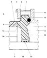
- the gas-insulated line shown in the single figure and identified by the reference numeral 1 is filled with an insulating gas, such as SF 6 , of up to a few bar pressure and contains an electrical conductor 3 which is held essentially centrally in an insulating tube 2.
- the insulating tube 2 is made of an optionally filler-reinforced plastic, such as a thermoplastic, in particular based on polyethylene, or a thermoset based on epoxy or polyester, and has on its outer surface a coating 4 made of electrically conductive or electrically semiconductive material, which is filled with an insulating gas and metal encapsulation 5 containing active electrical parts.
- the coating 4 ensures a defined zero potential on the outer surface of the insulating tube 2 and homogenizes the electric field in the gas space between the current conductor 3 and the insulating tube 2.
- the current conductor 3 is guided through a housing opening into the interior of the metal encapsulation 5.
- An end piece 6 of the gas-insulated line 1 has a mounting flange 7, which is preferably made of the same material as the insulating tube 2.
- the mounting flange 7 is clamped gas-tight with a flange 11 of the metal encapsulation 5 by means of a pressure ring 8, tensioning screws 9 and a sealing ring 10.
- the end piece 6 also contains a rotationally symmetrical, circular disk or optionally also funnel or wave-shaped arc barrier 12.
- This arc barrier is molded onto the mounting flange 7 made of the same material and extends into the interior of the insulating tube 2 up to the outer surface of the current conductor 3.
- the arc barrier 12 carries on the inner surface facing the current conductor 3 a shield 13 resting on the outer surface made of an electrically conductive or semiconducting material.
- the material of the shield 13 contains the same plastic, in particular HD polyethylene, such as the insulating tube 2 or the arc barrier 12 and additionally at least 10 percent by weight of electrically conductive or semiconducting parts, for example conductivity soot.
- sealing rings 14 which between the Arc barrier 12 and the outer surface of the conductor 3 are arranged and surrounding the current conductor, care is taken that the gas-insulated Line 1 is sealed gastight.
- the end piece 6 and the insulating tube 2 contain thermoplastic material, especially HD polyethylene. Both parts can then in a simple manner, for example by welding, cohesively be connected to each other.
- the end piece 6 a left-facing pipe extension 15, which with the right end of the insulating tube 2 is integrally connected.
- Such a gas-insulated line 1 can advantageously be produced as follows become.
- the insulating tube 2 provided with the coating 4 is through Coextrusion of a thermoplastic insulating material and an electrical one conductive or semiconductive base material.
- the coating 4 is removed.
- the pipe socket 15 of the End piece 6 and thus also the mounting flange 7 and Arc barrier 12 are with the coating-free right end of the Insulated pipe 2 welded.
- coating material is applied to the one that is formed.
Landscapes
- Installation Of Bus-Bars (AREA)
- Cable Accessories (AREA)
Applications Claiming Priority (2)
| Application Number | Priority Date | Filing Date | Title |
|---|---|---|---|
| DE19737674 | 1997-08-29 | ||
| DE1997137674 DE19737674A1 (de) | 1997-08-29 | 1997-08-29 | Gasisolierte Leitung und Verfahren zur Herstellung dieser Leitung |
Publications (1)
| Publication Number | Publication Date |
|---|---|
| EP0899844A1 true EP0899844A1 (fr) | 1999-03-03 |
Family
ID=7840547
Family Applications (1)
| Application Number | Title | Priority Date | Filing Date |
|---|---|---|---|
| EP98810826A Withdrawn EP0899844A1 (fr) | 1997-08-29 | 1998-08-21 | Conducteur à isolation par gaz et méthode pour le fabriquer |
Country Status (4)
| Country | Link |
|---|---|
| EP (1) | EP0899844A1 (fr) |
| JP (1) | JPH11176251A (fr) |
| CA (1) | CA2245756A1 (fr) |
| DE (1) | DE19737674A1 (fr) |
Families Citing this family (2)
| Publication number | Priority date | Publication date | Assignee | Title |
|---|---|---|---|---|
| JP6071209B2 (ja) * | 2012-02-21 | 2017-02-01 | 株式会社東芝 | ガス絶縁開閉装置、及びガス絶縁母線 |
| DE102012215393A1 (de) * | 2012-08-30 | 2014-03-06 | Siemens Aktiengesellschaft | Elektrische Isolatoranordnung |
Citations (7)
| Publication number | Priority date | Publication date | Assignee | Title |
|---|---|---|---|---|
| DE2157101A1 (de) * | 1971-11-12 | 1973-05-17 | Siemens Ag | Gekapselte hochspannungsschaltanlage |
| DE2403395A1 (de) * | 1974-01-22 | 1975-07-24 | Siemens Ag | Anordnung zur spannungszufuehrung zu einer metallgekapselten hochspannungseinrichtung |
| EP0457081A1 (fr) * | 1990-05-17 | 1991-11-21 | Asea Brown Boveri Ag | Isolateur |
| EP0597147A1 (fr) * | 1992-11-13 | 1994-05-18 | GEC Alsthom T&D AG | Installation blindée à haute tension et assemblage pour une telle installation |
| EP0750379A2 (fr) * | 1995-06-23 | 1996-12-27 | Mitsubishi Denki Kabushiki Kaisha | Entretoise isolant et procédé pour la fabrication d'un électrode de blindage |
| EP0774817A2 (fr) * | 1995-11-15 | 1997-05-21 | Asea Brown Boveri Ag | Appareillage à isolation par gaz |
| EP0789437A2 (fr) * | 1996-02-08 | 1997-08-13 | Asea Brown Boveri Ag | Section de conduit à isolation par gaz |
-
1997
- 1997-08-29 DE DE1997137674 patent/DE19737674A1/de not_active Withdrawn
-
1998
- 1998-08-20 JP JP23458498A patent/JPH11176251A/ja not_active Withdrawn
- 1998-08-21 EP EP98810826A patent/EP0899844A1/fr not_active Withdrawn
- 1998-08-25 CA CA 2245756 patent/CA2245756A1/fr not_active Abandoned
Patent Citations (7)
| Publication number | Priority date | Publication date | Assignee | Title |
|---|---|---|---|---|
| DE2157101A1 (de) * | 1971-11-12 | 1973-05-17 | Siemens Ag | Gekapselte hochspannungsschaltanlage |
| DE2403395A1 (de) * | 1974-01-22 | 1975-07-24 | Siemens Ag | Anordnung zur spannungszufuehrung zu einer metallgekapselten hochspannungseinrichtung |
| EP0457081A1 (fr) * | 1990-05-17 | 1991-11-21 | Asea Brown Boveri Ag | Isolateur |
| EP0597147A1 (fr) * | 1992-11-13 | 1994-05-18 | GEC Alsthom T&D AG | Installation blindée à haute tension et assemblage pour une telle installation |
| EP0750379A2 (fr) * | 1995-06-23 | 1996-12-27 | Mitsubishi Denki Kabushiki Kaisha | Entretoise isolant et procédé pour la fabrication d'un électrode de blindage |
| EP0774817A2 (fr) * | 1995-11-15 | 1997-05-21 | Asea Brown Boveri Ag | Appareillage à isolation par gaz |
| EP0789437A2 (fr) * | 1996-02-08 | 1997-08-13 | Asea Brown Boveri Ag | Section de conduit à isolation par gaz |
Also Published As
| Publication number | Publication date |
|---|---|
| DE19737674A1 (de) | 1999-03-04 |
| CA2245756A1 (fr) | 1999-02-28 |
| JPH11176251A (ja) | 1999-07-02 |
Similar Documents
| Publication | Publication Date | Title |
|---|---|---|
| EP2431982B1 (fr) | Ligne enfichable et installation haute tension dotée d'une telle ligne | |
| EP0744803A2 (fr) | Sectionneur pour une installation de commutation à haute tension, blindé et à isolation gazeuse | |
| DE69738421T2 (de) | Kabelendstück | |
| DE2021066A1 (de) | Gekapselte gasisolierte Hochspannungsleitung | |
| DE4240118C1 (de) | Durchführung, insbesondere für hohe Spannungen mit spezieller Elektrodenhalterung | |
| EP0789438A2 (fr) | Section de conduit à isolation par gaz | |
| EP2600358B1 (fr) | Parafoudre | |
| EP0789437A2 (fr) | Section de conduit à isolation par gaz | |
| EP1380084B1 (fr) | Liaison a barre collectrice | |
| EP0899844A1 (fr) | Conducteur à isolation par gaz et méthode pour le fabriquer | |
| EP0774816A2 (fr) | Conduit à isolation par gaz | |
| DE2928727A1 (de) | Kabelendverschluss fuer mittelspannungsund hochspannungskabel | |
| DE19746313A1 (de) | Kabelendverschluß oder Kabelmuffe mit geometrischer Feldsteuerung | |
| DE19845006C1 (de) | Oberirdische Kabelverbindung | |
| DE2233217A1 (de) | Trommelbare kabellaenge eines gasisolierten hochspannungskabels | |
| DE19856025C2 (de) | Kompakte Übergangsmuffe | |
| EP0789424A2 (fr) | Elément de raccord pour deux sections de conducteur à haute tension | |
| EP1417689B1 (fr) | Traversee haute-tension | |
| DE10139251C1 (de) | Sammelschienenverbindung | |
| DE3639626A1 (de) | Durchfuehrung fuer elektrische leiter | |
| EP0774817A2 (fr) | Appareillage à isolation par gaz | |
| EP0651400B1 (fr) | Traversée avec supports d'électrode spéciaux en particulier pour haute tension | |
| EP2403087A1 (fr) | Arrangement pour relier deux câbles à haute tension isolés au papier | |
| DE1949503B2 (de) | Masseloser Endenabschluß | |
| DE2202401B2 (de) | Gekapselte gasisolierte Hochspannungsleitung |
Legal Events
| Date | Code | Title | Description |
|---|---|---|---|
| PUAI | Public reference made under article 153(3) epc to a published international application that has entered the european phase |
Free format text: ORIGINAL CODE: 0009012 |
|
| AK | Designated contracting states |
Kind code of ref document: A1 Designated state(s): CH DE FR GB LI SE |
|
| AX | Request for extension of the european patent |
Free format text: AL;LT;LV;MK;RO;SI |
|
| 17P | Request for examination filed |
Effective date: 19990119 |
|
| AKX | Designation fees paid |
Free format text: CH DE FR GB LI SE |
|
| RAP1 | Party data changed (applicant data changed or rights of an application transferred) |
Owner name: ABB HOCHSPANNUNGSTECHNIK AG |
|
| STAA | Information on the status of an ep patent application or granted ep patent |
Free format text: STATUS: THE APPLICATION HAS BEEN WITHDRAWN |
|
| 18W | Application withdrawn |
Withdrawal date: 20001021 |