EP0900162B1 - Vorratsbehälteranordnungen für hydraulische fahrzeugbremssysteme - Google Patents
Vorratsbehälteranordnungen für hydraulische fahrzeugbremssysteme Download PDFInfo
- Publication number
- EP0900162B1 EP0900162B1 EP97923160A EP97923160A EP0900162B1 EP 0900162 B1 EP0900162 B1 EP 0900162B1 EP 97923160 A EP97923160 A EP 97923160A EP 97923160 A EP97923160 A EP 97923160A EP 0900162 B1 EP0900162 B1 EP 0900162B1
- Authority
- EP
- European Patent Office
- Prior art keywords
- chamber
- fluid
- reservoir assembly
- volume
- reservoir
- Prior art date
- Legal status (The legal status is an assumption and is not a legal conclusion. Google has not performed a legal analysis and makes no representation as to the accuracy of the status listed.)
- Expired - Lifetime
Links
- 230000000712 assembly Effects 0.000 title description 3
- 238000000429 assembly Methods 0.000 title description 3
- 239000012530 fluid Substances 0.000 claims description 88
- 239000000945 filler Substances 0.000 claims description 22
- 230000002706 hydrostatic effect Effects 0.000 claims description 13
- 238000010276 construction Methods 0.000 description 8
- 238000012546 transfer Methods 0.000 description 7
- 230000000694 effects Effects 0.000 description 6
- 230000008859 change Effects 0.000 description 5
- 238000001514 detection method Methods 0.000 description 5
- 239000012528 membrane Substances 0.000 description 5
- 230000015556 catabolic process Effects 0.000 description 4
- 238000006731 degradation reaction Methods 0.000 description 4
- 230000006866 deterioration Effects 0.000 description 4
- 238000000034 method Methods 0.000 description 4
- 230000005012 migration Effects 0.000 description 3
- 238000013508 migration Methods 0.000 description 3
- 230000005574 cross-species transmission Effects 0.000 description 2
- 238000007599 discharging Methods 0.000 description 2
- 238000009434 installation Methods 0.000 description 2
- 230000004048 modification Effects 0.000 description 2
- 238000012986 modification Methods 0.000 description 2
- 230000009467 reduction Effects 0.000 description 2
- 238000007789 sealing Methods 0.000 description 2
- 230000032683 aging Effects 0.000 description 1
- 238000013459 approach Methods 0.000 description 1
- 239000011324 bead Substances 0.000 description 1
- 230000000903 blocking effect Effects 0.000 description 1
- 230000008602 contraction Effects 0.000 description 1
- 239000013536 elastomeric material Substances 0.000 description 1
- 238000004146 energy storage Methods 0.000 description 1
- 230000007774 longterm Effects 0.000 description 1
- 239000000463 material Substances 0.000 description 1
- 239000002184 metal Substances 0.000 description 1
- 230000008569 process Effects 0.000 description 1
- 230000000717 retained effect Effects 0.000 description 1
Images



Classifications
-
- B—PERFORMING OPERATIONS; TRANSPORTING
- B60—VEHICLES IN GENERAL
- B60T—VEHICLE BRAKE CONTROL SYSTEMS OR PARTS THEREOF; BRAKE CONTROL SYSTEMS OR PARTS THEREOF, IN GENERAL; ARRANGEMENT OF BRAKING ELEMENTS ON VEHICLES IN GENERAL; PORTABLE DEVICES FOR PREVENTING UNWANTED MOVEMENT OF VEHICLES; VEHICLE MODIFICATIONS TO FACILITATE COOLING OF BRAKES
- B60T11/00—Transmitting braking action from initiating means to ultimate brake actuator without power assistance or drive or where such assistance or drive is irrelevant
- B60T11/10—Transmitting braking action from initiating means to ultimate brake actuator without power assistance or drive or where such assistance or drive is irrelevant transmitting by fluid means, e.g. hydraulic
- B60T11/26—Reservoirs
Definitions
- This invention relates to reservoir assemblies for vehicle hydraulic braking systems.
- a reservoir assembly having the features of the preamble of claim 1 is known for example from US-A-4 981 016.
- each circuit is supplied with hydraulic fluid from a dedicated reservoir.
- a braking system may be of the brake-by-wire electro-hydraulic type (EMB) in which the control valve comprises a solenoid-operated valve which is operated by an energising current from an electronic control unit and of which the magnitude is determined by operation of a brake-pedal.
- EMB brake-by-wire electro-hydraulic type
- the source of hydraulic fluid under pressure may be provided by a gas-charged hydraulic accumulator.
- Faults which may cause fluid to transfer from one reservoir to the other may comprise:
- the problem can be overcome by the provision of two separate reservoirs, each provided with an individual filling point.
- the two reservoirs it is preferable for the two reservoirs to have a single, common, filling point.
- the most convenient way to achieve this would be to combine the two reservoirs into a common tank containing two chambers separated by a baffle in a manner similar to known reservoirs fitted to pedal-operated master cylinders of the tandem type.
- Such a combined tank will neatly avoid the risk of over flow from a reservoir, but will neutralise attempts to detect those faults causing fluid transfer. Excess fluid in one chamber of the tank will spill over into the other chamber, so that the levels will not change.
- baffle height it would, of course, be a simple matter to arrange for the baffle height to exceed the normal maximum level for one of the two chambers, but this would only allow transfer detection in one sense. Such transfer cannot take place in an opposite direction from the chamber of the first power circuit to the chamber of the second back-up hydrostatic circuit because after filling the tank, the fluid level in the chamber for the second back-up hydrostatic circuit will always be level with the top of the baffle. Any additional fluid introduced, for example to compensate for leakage due to a blocked return line as described above, will merely flow over the baffle and back into the chamber supplying the first power circuit.
- our invention provides a reservoir assembly for a vehicle hydraulic braking system including at least one chamber for storage of hydraulic fluid, and a filling cap, adapted to be fitted onto the reservoir assembly to seal a filler opening for the chamber, characterised in that the reservoir assembly is provided with means for increasing the effective volume of the chamber said means being operative automatically with fitting of the filling cap onto the reservoir assembly to seal the filler opening.
- a reservoir assembly for a vehicle hydraulic braking system comprising a common tank for hydraulic fluid which is divided internally into first and second chambers by means of an imperforate baffle and the tank has a single filler opening adapted to be closed by a filling cap and through which one of the chambers can be filled directly with the other chamber being filled indirectly to a given level by spillage over the baffle, the said one chamber is provided with means for increasing its effective volume automatically with fitting of the filling cap onto the tank to seal the filler opening.
- Increasing the effective volume of the said one chamber ensures that the fluid level in that chamber is reduced below baffle height sufficiently to prevent fluid from that chamber from spilling over the baffle and into the other chamber. This is achieved by accommodating a given volume of fluid in a chamber of which the effective volume has been increased.
- the said one chamber supplies fluid to the second back-up hydrostatic circuit and the other chamber supplies fluid to the first power circuit.
- This enables any transfer of fluid, for example because of seal leakage, from the power circuit to the hydrostatic circuit to be detected as a result of change in the level of fluid in the said one chamber. Unless the original level is below baffle height it will merely spill over.
- the means for increasing the effective volume of the said chamber comprises a hollow member housed within the chamber and moveable from the first position, in which it defines within the chamber a first given volume, into a second position, in which the effective volume of the chamber is increased to a second given volume, and in which the volume of fluid which can then be accommodated within the chamber lies below the baffle height.
- the hollow member may comprise a bellows which is located in the fully extended position when the chamber is filled with fluid and in which the chamber is of a first given volume but which is contracted by co-operation with the filler cap to increase the effective volume of the chamber to the second given volume.
- the bellows is sealed from the interior of the chamber so that no fluid enters the bellows.
- the interior of the bellows may be exhausted to atmosphere. Alternatively it may be connected by a pipe into the reservoir above the fluid level. Not only does this ensure that no vacuum is created within the interior of the bellows, but it also enables any fluid permeating through the wall of the bellows to be returned to the reservoir, rather than be lost to the system.
- the hollow member may comprise a hollow bucket which is displaced downwardly into the chamber as the filler cap is fitted onto the tank, initial movement of the bucket acting to displace the fluid over the baffle into the other chamber and reduce the effective volume of the chamber to a given value with subsequent movement of the bucket below the surface of the fluid acting to accommodate fluid within the bucket by spillage over its rim, whereby to lower the level of fluid within the chamber below the baffle height and reduce the effective volume of the chamber to said given volume.
- the system can monitor the charging-time needed to achieve a given rise in accumulator pressure. Whilst this can be indicative of pre-charged pressure the absence of any change on the expected result will not mean that a fault had not occurred.
- the effects upon charging time of pre-charged loss would be similar, but in the opposite sense, to the effects of a similar degree of loss in the efficiency of a pump for charging the accumulator.
- the occurrence of either one of the two faults, without the other could be reliably detected, but such detection would be difficult to achieve if both components deteriorated at the same time.
- Fluid leakage from the pressurised system to the reservoir during charging, for example through the control valve would have a similar effect to that of reduced pump efficiency.
- the pressure of the gas depends not only upon the remaining mass of gas, but also upon its temperature. That is to say the charging time will vary with temperature even if no gas leakage has occurred. In the absence of temperature data only large gas losses, greater than substantially 40%, could be reliably detected, even without pump degradation or leakage. Thus adequate warnings cannot be guaranteed by this method under realistic operating conditions, unless gas temperature can be inferred.
- the reservoir is provided with a proportional fluid level sensor.
- the source of hydraulic fluid under pressure comprises a gas charged hydraulic accumulator.
- the proportional fluid level sensor enables the system to identify loss of volume in the reservoir, for example due to withdrawal of fluid from the reservoir to compensate for change in volume in the accumulator as a result of migration of gas through the membrane in the accumulator and/or degradation of the pump for charging the accumulator.
- a loss of volume as indicated by the sensor is indicative of loss of pressure in the accumulator.
- the detection process will involve comparing against predetermined expectations the volume drawn from the reservoir during charging between two pressures. i.e. ml/bar, not just ml.
- the expectations could be formulated quite accurately, enabling relatively small gas losses to be detected; although still not instantly. If, as will almost certainly be the case, ambient temperature is unknown, or has to be inferred from other data, then the expectations must be formed with a correspondingly larger tolerance, i.e. larger gas losses will be needed before confident detection will be possible.
- the reservoir assembly illustrated in Figures 1-3 of the accompanying drawings comprises a tank 1 which is divided into a first chamber 2 and a second chamber 3 by means of an upstanding imperforate baffle 4.
- the tank 1 is adapted to be filled through a single filler opening 5 immediately over the chamber 2 with the chamber 3 being filled by spillage over the baffle 4.
- the chamber 2 supplies fluid to a back-up hydrostatic circuit through an outlet 6, and the chamber 3 supplies fluid to a power circuit with fluid being supplied to a pump from an outlet 7 and returned to the reservoir assembly through an inlet 8.
- Each chamber 2, 3 is supplied with respective fluid level sensors 9, 10.
- a flexible bellows 12 is housed within the chamber 2 being upstanding from its base 13. As illustrated in Figure 3 an edge of the base 13 surrounding an opening and comprising an exhaust is sealingly received in an outwardly directed sealing groove at the base of the bellows 12. At its upper end the bellows 12 is sealed from the interior of the chamber.
- a circular plate 15 is carried from the lower end of a rod 16 which, in turn, depends axially from a filler cap 17 for sealing the filler opening 5.
- the bellows 12 is normally fully extended to reduce the effective volume of the chamber 2.
- the tank is filled through the filler opening 5 with fluid spilling over the baffle 4 until that fluid in the chamber 3 is at a desired level, as indicated by a marking on the tank. At that point fluid in the chamber 2 is substantially at baffle height.
- the filler cap 17 is replaced, initially with a small volume of fluid being displaced over the baffle 4 and into the chamber 3 by the volume of the entering plate 15 and the rod 16.
- the plate 16 then co-operates with the upper end of the bellows 12 and progressively contracts the bellows 12 to its fully contracted position illustrated in Figure 2.
- Such contraction of the bellows 12 reduces the effective volume of the chamber 2 in order to lower the level of fluid in that chamber from baffle height to a desired maximum level below baffle height.
- the interior of the bellows 12 is connected to the upper end of the tank through a pipe 20.
- the lower end of the bellows has a radial bead 21 which seals around an upstanding rim 22 surrounding an opening in the base 13 and which leads to the pipe 20.
- the bellows 12 is omitted and a hollow bucket 30 is carried from the lower end of the rod 16.
- the bucket comprises a container having an upper or top wall 31 of perforated construction and by means of which the bucket 30 is carried from the rod 16.
- both chambers 2 and 3 of the tank 1 are filled as described above.
- the bucket When the level in the chamber 3 is at baffle height the bucket is inserted into the chamber 2, initially to displace the fluid from the chamber 2 over the baffle 4 and into the chamber 3.
- the plate 31 When the plate 31 is submerged fluid enters the bucket 30 through the perforations in the top wall 31, in turn to accommodate the fluid from the chamber 2, thereby reducing its effective volume and, in consequence, fluid level below baffle height.
- the bucket 30 includes drain openings through which fluid can drain back into the chamber 2 as the filler cap 17 is removed from the tank 1.
- the filler opening 5 supplies fluid directly to the chamber 3 for the pump circuit, and the rod 16 co-operates with the bellows 12 which is itself housed within the chamber 3, through the circular plate 15.
- the inlet 8 to the chamber 3 is located in the wall of the tank above maximum fluid level 40 substantially determined by the baffle height.
- the tank will be filled to the maximum level 40. However, should the tank be filled to a height above that level, which might be permitted by additional volume above the baffle 4, then the risk of overflow is serious.
- the bellows 12 is contracted to increase the effective volume of the chamber 3, whereby to accommodate any excess fluid below the maximum fluid level line 40, including any fluid returned from the accumulator through the inlet 8.
- the capacity of the bellows 12 is chosen to be sufficient to accommodate the maximum stored volume, thus ensuring that overflow will not occur.
- the walls of the tank may be of stepped or increased thickness in a direction towards the base of the tank.
- an acoustic transducer may be incorporated as a fluid-level sensing means, with the transducer operating in the ultrasonic range.
- a pulse of sound is generated by a small strip of piezo material located in the side of the tank and acting as a loudspeaker.
- the transducer is then switched to act as a microphone, so that the presence or absence of fluid at the inner tank wall can be deduced from the amplitude of the reflected signal. (Arrival time can be used as well if a metal reflector is positioned opposite the sensor.)
- an electrically-partitioned strip is aligned behind the stepped wall section of the tank (in the vertical direction), then the step at which fluid is first detected would be easy to identify.
- Such a multi-stage switched (quaisi-proportional) sensor could constitute each of the sensors 9 and 10 in the construction described above.
- a first power circuit 51 is provided for applying brakes 52, 53, 54, 55 on wheels 56, 57, 58, 59 for normal service braking, and an emergency or hydraulic brake circuit 60 is provided for applying the brakes on failure of the power circuit 51.
- the power circuit 51 comprises a pump 61 driven by a motor 62 and which is adapted to draw fluid from a reservoir 63 in order to charge an hydraulic accumulator 64 which, in turn, provides the power to apply the brakes for normal service braking under the control of a master solenoid-operated control valve 65.
- An energising current to operate the control valve 65 is supplied from an electronic control unit 66 which, in turn, receives demand signals from a potentiometer 67 responsive to driver operation of a pedal 68.
- the pedal 68 Upon failure of the power circuit 51 the pedal 68 operates a master cylinder 69 comprising the hydrostatic circuit 60.
- the accumulator 64 is of the gas-charged type in which a volume of gas under pressure is disposed in a chamber 70 separated from hydraulic fluid in a chamber 71 by means of a flexible membrane 72 constructed of elastomeric material.
- the reservoir 63 is provided with a proportional level sensor 75 which provides a continuous indication of the volume of fluid in the reservoir.
- a proportional level sensor 75 which provides a continuous indication of the volume of fluid in the reservoir.
- the reservoir 63 for the power circuit 51 is separate from a reservoir 79 for the master cylinder 69.
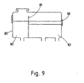
- the two reservoirs are combined into a single reservoir assembly as illustrated in Figure 9 of the accompanying drawings.
- a tank 80 is divided by a baffle 81 into a larger chamber 82 and a smaller chamber 83.
- the larger chamber 82 defines the reservoir for the power circuit 51
- the smaller chamber 83 defines the reservoir for the hydrostatic circuit 60.
- the larger chamber 82 is provided with a proportional level sensor 85 which performs the same function as the level sensor 75 illustrated in the layout of Figure 8.
- the pressure could be measured by deliberately discharging the accumulator completely pressure will drop to about zero, then starting the pump and either noting the pressure after a very short duration (e.g. 1 second, 5 cc) or when the initial very sharp pressure rise rate has fallen. Another method would be to note the pressure at the minimum fall rate, which would be just before the accumulator reaches complete discharge. The obvious problem with either of these is that it temporarily disables normal brake operation. The key may be to establish some safe condition when brakes will not be required, such as stationary with parking brake applied.
Landscapes
- Engineering & Computer Science (AREA)
- Transportation (AREA)
- Mechanical Engineering (AREA)
- Supply Devices, Intensifiers, Converters, And Telemotors (AREA)
- Transmission Of Braking Force In Braking Systems (AREA)
Claims (10)
- Reservoireinheit für ein hydraulisches Fahrzeugbremssystem mit mindestens einer Kammer (2) zum Speichern von Hydraulikfluid und einer Einfüllkappe (17), die auf der Reservoireinheit angebracht zu werden vermag, um eine Einfüllöffnung (5) für die Kammer (2) abzudichten, dadurch gekennzeichnet, dass die Reservoireinheit mit einer Einrichtung (12) zur Vergrößerung des effektiven Volumens der Kammer versehen ist, wobei die Einrichtung (12) automatisch mit dem Anbringen der Einfüllkappe (17) auf der Reservoireinheit zum Abdichten der Einfüllöffnung (5) wirksam ist.
- Reservoireinheit nach Anspruch 1, dadurch gekennzeichnet, dass sie einen gemeinsamen Behälter (1) für Hydraulikfluid umfasst, der innen mittels einer unperforierten Wand (4) in erste und zweite Kammern (2, 3) unterteilt ist, wobei der Behälter eine einzige Einfüllöffnung (5) aufweist, die durch die Einfüllkappe (17) geschlossen zu werden vermag und durch die eine der Kammern (2) direkt befüllt werden kann, wobei die andere Kammer indirekt durch Überlaufen über die Wand bis zu einem vorgegebenen Niveau gefüllt wird, wodurch in der einen Kammer (2) die Einrichtung (12) zur automatischen Vergrößerung ihres effektiven Volumens mit dem Anbringen der Einfüllkappe (17) an dem Behälter zum Abdichten der Einfüllöffnung (5) bereitgestellt ist.
- Reservoireinheit nach Anspruch 2, bei der die Einrichtung (12) zur Vergrößerung des effektiven Volumens der Kammer (2) ein hohles Element umfasst, das in der Kammer aufgenommen und von der ersten Stellung, in der es in der Kammer ein erstes gegebenes Volumen definiert, in eine zweite Stellung bewegbar ist, in der das effektive Volumen der Kammer auf ein zweites gegebenes Volumen vergrößert ist, und in der das Fluidvolumen, das dann in der Kammer aufgenommen werden kann, unter der Höhe der Wand (4) liegt.
- Reservoireinheit nach einem der vorhergehenden Ansprüche, bei der die Einrichtung zur Vergrößerung des Volumens einen Faltenbalg umfasst, der sich in der voll expandierten Stellung befindet, wenn die Kammer (2) mit Fluid gefüllt ist und in der die Kammer ein erstes gegebenes Volumen aufweist, der jedoch durch Zusammenwirken mit der Einfüllkappe (17) kontrahiert wird, um das effektive Volumen der Kammer auf das zweite gegebene Volumen zu vergrößern.
- Reservoireinheit nach Anspruch 4, bei der der Faltenbalg (12) vom Inneren der Kammer (2) abgesperrt ist, so dass kein Fluid in den Faltenbalg eintritt.
- Reservoireinheit nach Anspruch 4 oder Anspruch 5, bei der das Innere des Faltenbalgs (12) in die Atmosphäre entleert wird.
- Reservoireinheit nach Anspruch 4 oder Anspruch 5, bei der der Faltenbalg (12) durch ein Rohr (20) mit dem Reservoirinneren über dem Fluidniveau verbunden ist.
- Reservoireinheit nach Anspruch 2, bei der ein hohles. Gefäß (30) nach unten in die Kammer (2) verschoben wird, wenn die Einfüllkappe (17) auf dem Behälter (1) angebracht wird, wobei die anfängliche Bewegung des Gefäßes eine Verschiebung des Fluids über die Wand (4) in die andere Kammer und eine Verringerung des effektiven Volumens der Kammer auf ein gegebenes Maß bewirkt und eine weitere Bewegung des Gefäßes unter die Oberfläche des Fluids eine Aufnahme des Fluids in dem Gefäß durch Überlaufen über seinen Rand bewirkt, um dadurch den Fluidpegel in der Kammer unter die Wandhöhe zu senken und das effektive Volumen der Kammer (12) im Vergleich zu dem gegebenen Maß zu vergrößern.
- Hydraulisches Fahrzeugbremssystem, bei dem eine Radbremse durch einen ersten Kraftkreislauf (51) mit einer hydraulischen Fluidquelle (64) unter der Steuerung eines Steuerventils (65) und einen zweiten hydrostatischen Reservekreislauf (60) betätigt zu werden vermag, der die Bremse bei einem Versagen des ersten Kreislaufs hydrostatisch von einem pedalbetätigten Hauptzylinder (69) betätigen kann, wobei jeder Kreislauf mit Fluid aus einer Reservoireinheit (80) nach einem der Ansprüche 3 bis 9 versorgt wird, bei der die eine Kammer (2) den zweiten hydrostatischen Reservekreislauf mit Fluid versorgt und die andere Kammer (3) den ersten Kraftkreislauf mit Fluid versorgt.
- Bremssystem nach Anspruch 9, bei dem das System vom elektrohydraulischen Brake-by-wire-Typ (EMB) ist, bei dem das Steuerventil (65) ein magnetbetätigtes Ventil umfasst, das durch einen Betätigungsstrom von einer elektronischen Steuereinheit (66) betätigt wird, dessen Größe durch die Betätigung eines Bremspedals (68) bestimmt wird, und bei dem die Reservoireinheit (80) mit einem im Wesentlichen proportionalen Fluidniveausensor (85) versehen ist.
Applications Claiming Priority (5)
| Application Number | Priority Date | Filing Date | Title |
|---|---|---|---|
| GB9611124 | 1996-05-29 | ||
| GBGB9611124.0A GB9611124D0 (en) | 1996-05-29 | 1996-05-29 | Improvements in reservoir assemblies for vehicle hydraulic braking systems |
| GBGB9611123.2A GB9611123D0 (en) | 1996-05-29 | 1996-05-29 | Improvements in vehicle hydraulic braking systems |
| GB9611123 | 1996-05-29 | ||
| PCT/GB1997/001327 WO1997045305A1 (en) | 1996-05-29 | 1997-05-15 | Reservoir assemblies for hydraulic vehicle braking systems |
Publications (2)
| Publication Number | Publication Date |
|---|---|
| EP0900162A1 EP0900162A1 (de) | 1999-03-10 |
| EP0900162B1 true EP0900162B1 (de) | 2004-02-11 |
Family
ID=26309406
Family Applications (1)
| Application Number | Title | Priority Date | Filing Date |
|---|---|---|---|
| EP97923160A Expired - Lifetime EP0900162B1 (de) | 1996-05-29 | 1997-05-15 | Vorratsbehälteranordnungen für hydraulische fahrzeugbremssysteme |
Country Status (4)
| Country | Link |
|---|---|
| US (1) | US6205783B1 (de) |
| EP (1) | EP0900162B1 (de) |
| DE (1) | DE69727563T2 (de) |
| WO (1) | WO1997045305A1 (de) |
Families Citing this family (5)
| Publication number | Priority date | Publication date | Assignee | Title |
|---|---|---|---|---|
| US6659857B2 (en) * | 2001-07-11 | 2003-12-09 | Flow Sciences, Inc. | Turbulence-free laboratory safety enclosure |
| FR2841610B1 (fr) * | 2002-06-28 | 2006-06-09 | Bosch Gmbh Robert | Reservoir de liquide hydraulique |
| FR2841520B1 (fr) * | 2002-06-28 | 2005-06-10 | Bosch Gmbh Robert | Reservoir de fluide hydraulique d'un vehicule pour circuit de freinage |
| DE102018214895A1 (de) * | 2018-09-03 | 2020-04-23 | Robert Bosch Gmbh | Elektrohydraulische Bremsanlage mit hydrostatischer Rückfallebene |
| JP2021094976A (ja) * | 2019-12-17 | 2021-06-24 | ボッシュ株式会社 | リザーバタンク |
Family Cites Families (9)
| Publication number | Priority date | Publication date | Assignee | Title |
|---|---|---|---|---|
| DE537667C (de) * | 1929-08-14 | 1931-11-05 | Maurice Charles | Vorrichtung zum selbsttaetigen Ausgleich von Temperaturschwankungen, besonders fuer hydraulische Bremsleitungen von Kraftfahrzeugen |
| DE2448680C3 (de) * | 1974-10-12 | 1978-09-21 | Alfred Teves Gmbh, 6000 Frankfurt | Ausgleichsbehälter für eine hydraulische Mehrkreisbremsanlage, insbesondere eine Fahrzeug-Bremsanlage |
| FR2452406A1 (fr) * | 1979-03-27 | 1980-10-24 | Transformat Mat Plastiques | Reservoir moule a deux cuves pour double circuit |
| US4455832A (en) * | 1981-09-02 | 1984-06-26 | The Bendix Corporation | Master cylinder |
| JPS58209648A (ja) * | 1982-06-01 | 1983-12-06 | Nissan Motor Co Ltd | 液面検知装置付リザ−バ |
| DE3239438A1 (de) * | 1982-10-25 | 1984-04-26 | Alfred Teves Gmbh, 6000 Frankfurt | Kunststoff-ausgleichsbehaelter fuer hydraulische bremsanlagen |
| DE3437575A1 (de) * | 1984-10-13 | 1986-04-17 | Alfred Teves Gmbh, 6000 Frankfurt | Hydraulische kraftfahrzeugbremsanlage mit blockierschutz |
| JPH0357760A (ja) * | 1989-07-25 | 1991-03-13 | Toyota Motor Corp | 液圧ブースタ装置 |
| US4981016A (en) * | 1989-11-24 | 1991-01-01 | General Motors Corporation | Master cylinder dip stick |
-
1997
- 1997-05-15 WO PCT/GB1997/001327 patent/WO1997045305A1/en not_active Ceased
- 1997-05-15 EP EP97923160A patent/EP0900162B1/de not_active Expired - Lifetime
- 1997-05-15 DE DE69727563T patent/DE69727563T2/de not_active Expired - Fee Related
-
1998
- 1998-11-25 US US09/199,537 patent/US6205783B1/en not_active Expired - Fee Related
Also Published As
| Publication number | Publication date |
|---|---|
| DE69727563T2 (de) | 2004-12-23 |
| WO1997045305A1 (en) | 1997-12-04 |
| DE69727563D1 (de) | 2004-03-18 |
| EP0900162A1 (de) | 1999-03-10 |
| US6205783B1 (en) | 2001-03-27 |
Similar Documents
| Publication | Publication Date | Title |
|---|---|---|
| CN101772442B (zh) | 制动控制系统 | |
| US5727852A (en) | Method and device for controlling an ABS antilock braking / ASR traction control system | |
| US8544962B2 (en) | Hydraulic brake system with controlled boost | |
| US6318817B1 (en) | Electro-hydraulic braking systems | |
| US5039175A (en) | Hydraulic brake system for vehicles | |
| US11472392B2 (en) | Method for operating a brake system for motor vehicles, and brake system | |
| US20030038538A1 (en) | Method for monitoring the emergency braking capability of an electrohydraulic braking system | |
| US7374253B2 (en) | Method for monitoring the air bleeding quality of an electrohydraulic braking system | |
| JP2009502594A (ja) | 滑り制御型のブーストブレーキングシステム | |
| KR19990087731A (ko) | 수동식 오동작 안전기를 가진 전자 브레이크 관리 시스템 | |
| US6205783B1 (en) | Reservoir assemblies for hydraulic vehicle braking systems | |
| JP2005508783A (ja) | 液圧ブレーキシステムのための小型タンク | |
| JP5223301B2 (ja) | ブレーキ制御装置 | |
| US12065112B2 (en) | Method for operating a braking system, and braking system | |
| US4749240A (en) | Slip-controlled brake system | |
| GB2403520A (en) | Determination of brake fluid consumption in electrohydraulic braking systems for automobiles | |
| JP4734285B2 (ja) | タンデム型マスタシリンダ装置 | |
| US20110025120A1 (en) | Brake system for automotive vehicle | |
| JP3484993B2 (ja) | 液圧ブレーキ装置 | |
| KR102899900B1 (ko) | 브레이크액을 확보하는 방법 | |
| CN117657096A (zh) | 制动装置、其控制方法和车辆 | |
| CN102112351A (zh) | 对机动车中的制动系统进行功能检验的方法 | |
| JP3251327B2 (ja) | 車両のブレ−キ装置 | |
| JP2524218Y2 (ja) | 圧力機器制御装置における蓄圧器の故障診断装置 | |
| US20050225167A1 (en) | Master brake cylinder unit for an electrohydraulic vehicle brake system |
Legal Events
| Date | Code | Title | Description |
|---|---|---|---|
| PUAI | Public reference made under article 153(3) epc to a published international application that has entered the european phase |
Free format text: ORIGINAL CODE: 0009012 |
|
| 17P | Request for examination filed |
Effective date: 19981130 |
|
| AK | Designated contracting states |
Kind code of ref document: A1 Designated state(s): DE FR GB |
|
| RAP1 | Party data changed (applicant data changed or rights of an application transferred) |
Owner name: LUCAS INDUSTRIES LIMITED |
|
| 17Q | First examination report despatched |
Effective date: 20010511 |
|
| RAP1 | Party data changed (applicant data changed or rights of an application transferred) |
Owner name: LUCAS INDUSTRIES LIMITED |
|
| GRAP | Despatch of communication of intention to grant a patent |
Free format text: ORIGINAL CODE: EPIDOSNIGR1 |
|
| GRAS | Grant fee paid |
Free format text: ORIGINAL CODE: EPIDOSNIGR3 |
|
| GRAA | (expected) grant |
Free format text: ORIGINAL CODE: 0009210 |
|
| AK | Designated contracting states |
Kind code of ref document: B1 Designated state(s): DE FR GB |
|
| REG | Reference to a national code |
Ref country code: GB Ref legal event code: FG4D |
|
| REF | Corresponds to: |
Ref document number: 69727563 Country of ref document: DE Date of ref document: 20040318 Kind code of ref document: P |
|
| ET | Fr: translation filed | ||
| PLBE | No opposition filed within time limit |
Free format text: ORIGINAL CODE: 0009261 |
|
| STAA | Information on the status of an ep patent application or granted ep patent |
Free format text: STATUS: NO OPPOSITION FILED WITHIN TIME LIMIT |
|
| 26N | No opposition filed |
Effective date: 20041112 |
|
| PGFP | Annual fee paid to national office [announced via postgrant information from national office to epo] |
Ref country code: FR Payment date: 20050517 Year of fee payment: 9 |
|
| PGFP | Annual fee paid to national office [announced via postgrant information from national office to epo] |
Ref country code: GB Payment date: 20060406 Year of fee payment: 10 |
|
| REG | Reference to a national code |
Ref country code: GB Ref legal event code: 732E |
|
| PGFP | Annual fee paid to national office [announced via postgrant information from national office to epo] |
Ref country code: DE Payment date: 20060531 Year of fee payment: 10 |
|
| GBPC | Gb: european patent ceased through non-payment of renewal fee |
Effective date: 20070515 |
|
| REG | Reference to a national code |
Ref country code: FR Ref legal event code: ST Effective date: 20080131 |
|
| PG25 | Lapsed in a contracting state [announced via postgrant information from national office to epo] |
Ref country code: DE Free format text: LAPSE BECAUSE OF NON-PAYMENT OF DUE FEES Effective date: 20071201 |
|
| PG25 | Lapsed in a contracting state [announced via postgrant information from national office to epo] |
Ref country code: GB Free format text: LAPSE BECAUSE OF NON-PAYMENT OF DUE FEES Effective date: 20070515 |
|
| PG25 | Lapsed in a contracting state [announced via postgrant information from national office to epo] |
Ref country code: FR Free format text: LAPSE BECAUSE OF NON-PAYMENT OF DUE FEES Effective date: 20070531 |
|
| PG25 | Lapsed in a contracting state [announced via postgrant information from national office to epo] |
Ref country code: FR Free format text: LAPSE BECAUSE OF NON-PAYMENT OF DUE FEES Effective date: 20060531 |