EP0900348B1 - Verteiler für aus mehreren flüssiggaspatronen stammendes brenngas - Google Patents
Verteiler für aus mehreren flüssiggaspatronen stammendes brenngas Download PDFInfo
- Publication number
- EP0900348B1 EP0900348B1 EP97921657A EP97921657A EP0900348B1 EP 0900348 B1 EP0900348 B1 EP 0900348B1 EP 97921657 A EP97921657 A EP 97921657A EP 97921657 A EP97921657 A EP 97921657A EP 0900348 B1 EP0900348 B1 EP 0900348B1
- Authority
- EP
- European Patent Office
- Prior art keywords
- manifold
- valve
- cartridge
- assembly
- cartridges
- Prior art date
- Legal status (The legal status is an assumption and is not a legal conclusion. Google has not performed a legal analysis and makes no representation as to the accuracy of the status listed.)
- Expired - Lifetime
Links
- 230000000712 assembly Effects 0.000 claims description 12
- 238000000429 assembly Methods 0.000 claims description 12
- 239000012530 fluid Substances 0.000 claims description 10
- 238000004891 communication Methods 0.000 claims description 9
- 238000006073 displacement reaction Methods 0.000 claims description 7
- 238000003780 insertion Methods 0.000 claims description 4
- 230000037431 insertion Effects 0.000 claims description 4
- 230000011664 signaling Effects 0.000 claims description 4
- 239000003638 chemical reducing agent Substances 0.000 description 6
- 230000008878 coupling Effects 0.000 description 5
- 238000010168 coupling process Methods 0.000 description 5
- 238000005859 coupling reaction Methods 0.000 description 5
- 238000009434 installation Methods 0.000 description 5
- 230000036961 partial effect Effects 0.000 description 5
- 230000006835 compression Effects 0.000 description 4
- 238000007906 compression Methods 0.000 description 4
- 230000000694 effects Effects 0.000 description 4
- 230000000717 retained effect Effects 0.000 description 4
- 238000010411 cooking Methods 0.000 description 3
- 238000010438 heat treatment Methods 0.000 description 3
- 230000004048 modification Effects 0.000 description 3
- 238000012986 modification Methods 0.000 description 3
- 230000002093 peripheral effect Effects 0.000 description 3
- 230000000007 visual effect Effects 0.000 description 3
- 230000015572 biosynthetic process Effects 0.000 description 2
- 239000007788 liquid Substances 0.000 description 2
- 239000000203 mixture Substances 0.000 description 2
- 239000000853 adhesive Substances 0.000 description 1
- 230000001070 adhesive effect Effects 0.000 description 1
- 230000008033 biological extinction Effects 0.000 description 1
- 238000006243 chemical reaction Methods 0.000 description 1
- 238000010276 construction Methods 0.000 description 1
- 238000001514 detection method Methods 0.000 description 1
- 230000009977 dual effect Effects 0.000 description 1
- 230000007717 exclusion Effects 0.000 description 1
- 238000000605 extraction Methods 0.000 description 1
- 238000007667 floating Methods 0.000 description 1
- 230000003993 interaction Effects 0.000 description 1
- 239000000463 material Substances 0.000 description 1
- 238000003801 milling Methods 0.000 description 1
- 238000000465 moulding Methods 0.000 description 1
- 210000002445 nipple Anatomy 0.000 description 1
- 230000002829 reductive effect Effects 0.000 description 1
- 230000002441 reversible effect Effects 0.000 description 1
- 230000003313 weakening effect Effects 0.000 description 1
Images



Classifications
-
- F—MECHANICAL ENGINEERING; LIGHTING; HEATING; WEAPONS; BLASTING
- F24—HEATING; RANGES; VENTILATING
- F24C—DOMESTIC STOVES OR RANGES ; DETAILS OF DOMESTIC STOVES OR RANGES, OF GENERAL APPLICATION
- F24C3/00—Stoves or ranges for gaseous fuels
- F24C3/04—Stoves or ranges for gaseous fuels with heat produced wholly or partly by a radiant body, e.g. by a perforated plate
- F24C3/06—Stoves or ranges for gaseous fuels with heat produced wholly or partly by a radiant body, e.g. by a perforated plate without any visible flame
- F24C3/062—Stoves or ranges for gaseous fuels with heat produced wholly or partly by a radiant body, e.g. by a perforated plate without any visible flame stoves
-
- F—MECHANICAL ENGINEERING; LIGHTING; HEATING; WEAPONS; BLASTING
- F17—STORING OR DISTRIBUTING GASES OR LIQUIDS
- F17C—VESSELS FOR CONTAINING OR STORING COMPRESSED, LIQUEFIED OR SOLIDIFIED GASES; FIXED-CAPACITY GAS-HOLDERS; FILLING VESSELS WITH, OR DISCHARGING FROM VESSELS, COMPRESSED, LIQUEFIED, OR SOLIDIFIED GASES
- F17C13/00—Details of vessels or of the filling or discharging of vessels
- F17C13/08—Mounting arrangements for vessels
- F17C13/084—Mounting arrangements for vessels for small-sized storage vessels, e.g. compressed gas cylinders or bottles, disposable gas vessels, vessels adapted for automotive use
-
- F—MECHANICAL ENGINEERING; LIGHTING; HEATING; WEAPONS; BLASTING
- F17—STORING OR DISTRIBUTING GASES OR LIQUIDS
- F17C—VESSELS FOR CONTAINING OR STORING COMPRESSED, LIQUEFIED OR SOLIDIFIED GASES; FIXED-CAPACITY GAS-HOLDERS; FILLING VESSELS WITH, OR DISCHARGING FROM VESSELS, COMPRESSED, LIQUEFIED, OR SOLIDIFIED GASES
- F17C2205/00—Vessel construction, in particular mounting arrangements, attachments or identifications means
- F17C2205/01—Mounting arrangements
- F17C2205/0123—Mounting arrangements characterised by number of vessels
- F17C2205/013—Two or more vessels
-
- F—MECHANICAL ENGINEERING; LIGHTING; HEATING; WEAPONS; BLASTING
- F17—STORING OR DISTRIBUTING GASES OR LIQUIDS
- F17C—VESSELS FOR CONTAINING OR STORING COMPRESSED, LIQUEFIED OR SOLIDIFIED GASES; FIXED-CAPACITY GAS-HOLDERS; FILLING VESSELS WITH, OR DISCHARGING FROM VESSELS, COMPRESSED, LIQUEFIED, OR SOLIDIFIED GASES
- F17C2205/00—Vessel construction, in particular mounting arrangements, attachments or identifications means
- F17C2205/01—Mounting arrangements
- F17C2205/0123—Mounting arrangements characterised by number of vessels
- F17C2205/013—Two or more vessels
- F17C2205/0134—Two or more vessels characterised by the presence of fluid connection between vessels
- F17C2205/0142—Two or more vessels characterised by the presence of fluid connection between vessels bundled in parallel
-
- F—MECHANICAL ENGINEERING; LIGHTING; HEATING; WEAPONS; BLASTING
- F17—STORING OR DISTRIBUTING GASES OR LIQUIDS
- F17C—VESSELS FOR CONTAINING OR STORING COMPRESSED, LIQUEFIED OR SOLIDIFIED GASES; FIXED-CAPACITY GAS-HOLDERS; FILLING VESSELS WITH, OR DISCHARGING FROM VESSELS, COMPRESSED, LIQUEFIED, OR SOLIDIFIED GASES
- F17C2205/00—Vessel construction, in particular mounting arrangements, attachments or identifications means
- F17C2205/03—Fluid connections, filters, valves, closure means or other attachments
- F17C2205/0302—Fittings, valves, filters, or components in connection with the gas storage device
- F17C2205/0311—Closure means
- F17C2205/032—Closure means pierceable
-
- F—MECHANICAL ENGINEERING; LIGHTING; HEATING; WEAPONS; BLASTING
- F17—STORING OR DISTRIBUTING GASES OR LIQUIDS
- F17C—VESSELS FOR CONTAINING OR STORING COMPRESSED, LIQUEFIED OR SOLIDIFIED GASES; FIXED-CAPACITY GAS-HOLDERS; FILLING VESSELS WITH, OR DISCHARGING FROM VESSELS, COMPRESSED, LIQUEFIED, OR SOLIDIFIED GASES
- F17C2205/00—Vessel construction, in particular mounting arrangements, attachments or identifications means
- F17C2205/03—Fluid connections, filters, valves, closure means or other attachments
- F17C2205/0302—Fittings, valves, filters, or components in connection with the gas storage device
- F17C2205/0323—Valves
-
- F—MECHANICAL ENGINEERING; LIGHTING; HEATING; WEAPONS; BLASTING
- F17—STORING OR DISTRIBUTING GASES OR LIQUIDS
- F17C—VESSELS FOR CONTAINING OR STORING COMPRESSED, LIQUEFIED OR SOLIDIFIED GASES; FIXED-CAPACITY GAS-HOLDERS; FILLING VESSELS WITH, OR DISCHARGING FROM VESSELS, COMPRESSED, LIQUEFIED, OR SOLIDIFIED GASES
- F17C2223/00—Handled fluid before transfer, i.e. state of fluid when stored in the vessel or before transfer from the vessel
- F17C2223/01—Handled fluid before transfer, i.e. state of fluid when stored in the vessel or before transfer from the vessel characterised by the phase
- F17C2223/0146—Two-phase
- F17C2223/0153—Liquefied gas, e.g. LPG, GPL
-
- F—MECHANICAL ENGINEERING; LIGHTING; HEATING; WEAPONS; BLASTING
- F17—STORING OR DISTRIBUTING GASES OR LIQUIDS
- F17C—VESSELS FOR CONTAINING OR STORING COMPRESSED, LIQUEFIED OR SOLIDIFIED GASES; FIXED-CAPACITY GAS-HOLDERS; FILLING VESSELS WITH, OR DISCHARGING FROM VESSELS, COMPRESSED, LIQUEFIED, OR SOLIDIFIED GASES
- F17C2270/00—Applications
- F17C2270/07—Applications for household use
- F17C2270/0709—Camping gas
-
- F—MECHANICAL ENGINEERING; LIGHTING; HEATING; WEAPONS; BLASTING
- F17—STORING OR DISTRIBUTING GASES OR LIQUIDS
- F17C—VESSELS FOR CONTAINING OR STORING COMPRESSED, LIQUEFIED OR SOLIDIFIED GASES; FIXED-CAPACITY GAS-HOLDERS; FILLING VESSELS WITH, OR DISCHARGING FROM VESSELS, COMPRESSED, LIQUEFIED, OR SOLIDIFIED GASES
- F17C2270/00—Applications
- F17C2270/07—Applications for household use
- F17C2270/0736—Capsules, e.g. CO2
-
- Y—GENERAL TAGGING OF NEW TECHNOLOGICAL DEVELOPMENTS; GENERAL TAGGING OF CROSS-SECTIONAL TECHNOLOGIES SPANNING OVER SEVERAL SECTIONS OF THE IPC; TECHNICAL SUBJECTS COVERED BY FORMER USPC CROSS-REFERENCE ART COLLECTIONS [XRACs] AND DIGESTS
- Y10—TECHNICAL SUBJECTS COVERED BY FORMER USPC
- Y10T—TECHNICAL SUBJECTS COVERED BY FORMER US CLASSIFICATION
- Y10T137/00—Fluid handling
- Y10T137/4673—Plural tanks or compartments with parallel flow
-
- Y—GENERAL TAGGING OF NEW TECHNOLOGICAL DEVELOPMENTS; GENERAL TAGGING OF CROSS-SECTIONAL TECHNOLOGIES SPANNING OVER SEVERAL SECTIONS OF THE IPC; TECHNICAL SUBJECTS COVERED BY FORMER USPC CROSS-REFERENCE ART COLLECTIONS [XRACs] AND DIGESTS
- Y10—TECHNICAL SUBJECTS COVERED BY FORMER USPC
- Y10T—TECHNICAL SUBJECTS COVERED BY FORMER US CLASSIFICATION
- Y10T137/00—Fluid handling
- Y10T137/4673—Plural tanks or compartments with parallel flow
- Y10T137/474—With housings, supports or stacking arrangements
-
- Y—GENERAL TAGGING OF NEW TECHNOLOGICAL DEVELOPMENTS; GENERAL TAGGING OF CROSS-SECTIONAL TECHNOLOGIES SPANNING OVER SEVERAL SECTIONS OF THE IPC; TECHNICAL SUBJECTS COVERED BY FORMER USPC CROSS-REFERENCE ART COLLECTIONS [XRACs] AND DIGESTS
- Y10—TECHNICAL SUBJECTS COVERED BY FORMER USPC
- Y10T—TECHNICAL SUBJECTS COVERED BY FORMER US CLASSIFICATION
- Y10T137/00—Fluid handling
- Y10T137/4673—Plural tanks or compartments with parallel flow
- Y10T137/4857—With manifold or grouped outlets
Definitions
- the present invention relates to a manifold/distributor assembly for combustible gas supplied from a plurality of liquefied-gas cartridges.
- the liquefied gas may be supplied in single-use sealed cartridges ( or even cartridges having a closing, non refill valve) of restricted dimensions -and limited-capacity, of the order of one litre or less, which, when exhausted, are discarded.
- the proposed solution does not ensure the service continuity and from the user standpoint does not provide adequate safety.
- a cartridge can be punctured by a pin, the pad then intercepting communication of the cartridge with the manifold, then, moving the cartridge away from the pin, the pad compression is released and the communication is established.
- connection opening or shut-off requires further a displacement of the cartridges, easy achievable with micro cartridges only.
- FR-A-2.076.256 discloses a cabinet and gas cylinders contained therein; the gas cylinders are connected to a common manifold, each cylinder through a respective pressure reducer and a respective shut-off tap.
- the -present invention aims to provide a manifold/distributor for combustible gas supplied from a plurality of liquefied-gas cartridges, which manifold/distributor is capable of performing as well as a refillable cylinder while in addition giving continuity of service, safety of use and ease of replacement of the cartridges, when exhausted, the supplying of which is particularly convenient, and can be carried out directly by the user, without the need to have recourse to a service centre.
- a manifold/distributor assembly comprising a frame forming a plurality of cartridge housings, at least partial housings, and a manifold provided with a plurality of valve assemblies each incorporating an actuation element for opening the cartridges, one for each cartridge housing, which valve assemblies are normally closed and are only opened when a cartridge is present in the respective housing, characterised by comprising a multiple-way tap, which puts a delivery conduit in fluid communication with the whole manifold, with portions thereof or with none of them.
- the manifold/distributor assembly can be provided with a pressure-reducing regulator, which is conventional per se, with outlet adapter for connection to a consumer appliance, for example a domestic cooker.
- the cartridges are preferably of the valve-type with screwed boss for cartridge mounting, of the standard type defined for instance by European Regulation EN 417, but with a modified bottom which enables their manual holding and their screwing even in case a plurality of cartridges is tightly juxtaposed.
- valve assemblies provide a double closing protection and consist in a shut-off valve, opened only in presence of a cartridge, coupled to the cartridge shut-off valve, and in a non return valve, cascade connected.
- the frame forms a container for the manifold and the cartridges which can be tightly closed for transportation or storing in very safe conditions.
- the tight container can be provided, for further safety, with a pressure detection device for detecting internal overpressure of the container resulting from gas leakage and for signalling the event.
- a vent pipe may also be provided to put the container in communication with the external ambient, so as to prevent local and indoor formation of inflammable gas mixture in case of gas leakage.
- a manifold/ distributor assembly consists essentially of a frame 1, preferably obtained by moulding a plastic material and forming a plurality of cylindrical containers or housings 2,3,4,5, 6,7,8,9,10, which are disposed parallel to one another, juxtaposed in a plurality of rows, and integral with one another, in the present case by means of connecting ribs such as 11.
- the housings are each provided with a neck 12, on which there is fixed a valve assembly 13, incorporating a puncturing needle, the outlet of which is connected to a shut-off tap such as 14, with manual actuation by lever or knob.
- outlets of the various taps are connected to one another by means of pipes 15, 16, 17, 18 which meet in a pressure reducer/regulator 19, which is conventional per se, with outlet adapter 20 for connection to a consumer appliance and which, in conjunction with the valve assemblies and with the taps, constitute a distributing manifold with selective control of a plurality of sources of combustible gas, each being in the form of a liquefied-gas cartridge which is housed in one of the containers.
- the insertion of the cartridges in the various containers is effected via the open lower end of the containers, into which there is screwed a closure base or alternatively just a radially configured ring 21 for clamping and retaining the cartridge.
- the cartridge which may be of known or commercially available type, is pressed against the valve assembly incorporating the puncturing needle which is disposed in the neck of the container and is punctured.
- the frame 1 forms not only the various cylindrical containers but also a surround 22, which is extended to rise above the various containers and which houses and protects the manifold, the shut-off taps and the reducer/regulator.
- the frame is, preferably but not necessarily, provided with two aligned support pivots, one of which, 23, can be seen in Fig. 1, to permit the installation thereof in a housing with the possibility of rotation, even if only partial, on the pivots.
- Figure 2 represents, in diametral cross-section, one of the cylindrical containers and the associated valve assembly incorporating a puncturing needle to show the structure and the operation thereof.
- the valve assembly consists of a body 23 which is essentially cylindrical and is provided, at one end, with a threaded extension 24 for connection to a shut-off tap 25 and, in an intermediate position, with a prismatic clamping flange 26.
- That portion 27 of the body 23 which is on the opposite side from the extension 24 in relation to the flange 26 is threaded to allow it to be screwed forcibly into an aperture formed in the upper neck 12 of the container 2.
- a clamping locking nut to be screwed onto the body portion 27, with interposition of the neck 12 between flange 26 and locking nut.
- a cylindrical housing communicating with the tap 25 via an aperture 28 formed in the extension 24, which housing is open at the opposite end from the extension.
- a compression spring 29 and a disc obturator 30 which is extended to form a puncturing needle 31 and retained within the housing by a threaded bushing 32 screwed into the body 23, through which bushing there passes the axially slidable puncturing needle 31.
- a resilient ring (o-ring) 33 interposed between needle 31 and bushing 32, ensures the leaktightness of the slidable coupling between needle and bushing.
- the needle 31 ends in a puncturing tip 34.
- An internal through hole places the tip 34 of the needle in communication with the peripheral surface of the disc 30 which, preferably but not necessarily, is suitably conical for coupling, in sealed fashion, with a similarly conical seating of the bushing 32.
- the disc is retained against the conical seating, formed in the bushing 32, by the thrust exerted by the compression spring.
- a resilient pad 35 which embraces the puncturing tip 34 and is supported by a rigid disc 38 which is fixed to the needle.
- Fig. 2 also shows a liquid gas cartridge 36, of conventional type, which is housed in the container 2.
- the cartridge 36 is shown in a position of partial insertion into the container 2, with the top dome 37 in contact with the pad 35.
- the cartridge Upon partial screwing-up of the clamping ring base 21 into the open end of the container 2, the cartridge is gradually pressed against the puncturing tip 34 and punctured.
- the cartridge Upon further screwing-up of the clamping base or ring 21, the cartridge is pressed further towards the neck 12 and acts, via the pad 35 which is compressed to the maximum extent, on the supporting disc 38, thereby pressing the needle up into the disc housing.
- the cartridge overcomes the reaction exerted by the spring 29, it forces the disc 30 to move away from its seating, causing the valve to open.
- an adhesive resilient patch 39 which has the function of retaining any chips that may be produced by the puncturing operation.
- This patch which is conveniently thickened, can operate as a resilient bung which, by reason of its elasticity, tends, when the cartridge is removed from the housing, to reclose, even though not hermetically, the aperture produced by the puncturing needle, thus reducing the escape of any residual gas contained in the cartridge which, under normal conditions of use, upon exhaustion of the cartridge, comes to be at a pressure approximately equal to or slightly greater than ambient pressure, for which reason the escape is very small and the total volume of gas which flows out is thus diluted in the atmospheric air so as not to constitute a risk factor.
- the disc valve In a first phase of unscrewing, the disc valve is closed automatically by the thrust exerted by the spring 29, preventing a flow of gas from the tap 25 to the needle, even if the tap 25 is inadvertently left open.
- a dual safety protection is thus provided.
- the thrust exerted by the resilient pad 35 causes an at least partial removal of the puncturing tip 34 from the cartridge which, when the unscrewing of the base 21 has been completed, can easily be removed from the container 2.
- Figures 5 and 6 represent, in front view and side view respectively, a preferred application of the described manifold/distributor assembly, in a cooker 40 of known type, which cooker is intended to be supplied by a liquefied-gas cylinder.
- Cookers of this type have a lateral space 41, closed by a door, to house a pressurized liquid gas cylinder.
- the assembly 100 is pivotally mounted on the pivots 42, 43 in a high position within the space 41, in order to be able to rotate, as shown in Fig. 6, and thus to permit an easy insertion and replacement of the cartridges in the housings of the assembly.
- the assembly 100 is connected to the rings 45 and to the oven burner, via a conventional flexible tube.
- the exhausted cartridges can be disconnected from the manifold by closing the respective taps and the reserve cartridges can be connected to the manifold by opening the respective taps, with a rapid restoration of the supply.
- the assembly which has been described may provide, rather than nine cylindrical containers arranged in three rows of three containers each, a larger or smaller number of containers.
- closure bases of the various containers may be externally screwed.
- Figure 7 is an exploded perspective view of this possible solution, and shows a container 2 provided with an external thread 46 on its open end.
- a cartridge 36 which is retained in the container by a base 21 which is screwed onto the thread 46.
- the base may partially house the cartridge 36, so as to facilitate the removal of the cartridge when the base is unscrewed and removed.
- the latter may be provided with an external milling 47 and/or with external lower fins 48.
- thread 46 is only illustrative and can be replaced by a bayonet coupling system.
- cartridges might be produced which are provided on the external cylindrical surface with projections for screw coupling or bayonet engagement in the cylindrical containers of the assembly 1, which containers are, for this purpose, provided with appropriate internal grooving or threading.
- Figure 8 shows, in a perspective view, partly in cross-section, this possible construction and shows a container 2 provided, on its internal cylindrical surface, with a pair of helical grooves which are radially opposite and one of which, 49, can be seen and into which there are inserted two projections 50, 51, which are radially opposite and which are formed on the external cylindrical surface of the cartridge 36.
- the grooves such as 49 form a bayonet engagement for the cartridge 36.
- grooves such as 49 may also constitute a continuous thread with two or more starts, for screw engagement of the cartridge, the latter also being provided with discontinuous projections or protuberances, or with a continuous threading.
- the cartridge should be provided with discontinuous projections or protuberances and not with a continuous thread, in order to avoid possible deformations due to the internal pressure of the cartridge which, otherwise, if the casing is not sufficiently rigid, might behave to some extent as a resilient bellows.
- Figure 9 represents, by way of example, a valve assembly with puncturing needle and shut-off tap which are integrated into a single associated unit, with actuation from the top, which is thus completely independent of the axial displacements of a cartridge in its housing.
- the cartridge may also be fixed in its housing by conventional hook systems.
- a puncturing knob 52 permits the screwing into a valve body 53, by means of a stem 54, of a screw sleeve 55 in which there is housed a valve disc 56, which is extended to form a puncturing needle 57.
- the disc is retained in its closed position by diaphragm springs 58 or equivalent means.
- the seating of the screw sleeve 55 is closed by a stopper 59, which is screwed onto the body 53 and is in its turn provided with a screw extension 60 for fastening to the neck of a cartridge housing, which is not illustrated.
- the puncturing needle 57 is able to slide axially through the stopper 59.
- a seating for a rotating obturator 61 for the shut-off tap In the body 53 there is also formed a seating for a rotating obturator 61 for the shut-off tap.
- the latter may be cylindrical, flat or preferably frustoconical, as illustrated, and is actuated by a lever 62 from closed positions to a predetermined open position.
- the stem 54 Passing freely through the rotating obturator 61 is the stem 54, which is free to slide axially and to rotate.
- Suitable seals positioned by nipples in a conventional manner ensure leaktightness between parts which are movable relative to one another.
- the puncturing needle In the position illustrated, the puncturing needle is in a retracted position, with the end of the stroke determined by contact between body 53 and sleeve 55.
- the rotary actuation of the knob 52 causes the sleeve 55 to be screwed into the body 53, with rotary and axial sliding movement, in a downward direction, of the knob 52, of the stem 54 and of the sleeve 55.
- the resilient pad 63 ensures leaktightness between needle 57 and cartridge and, once compressed to the maximum extent by interaction with the cartridge, causes the disc valve 56 to open.
- the disc valve 56 In the absence of a cartridge, the disc valve 56 remains closed, guaranteeing maximum safety even in the case where the shut-off tap, formed by the obturator 61, is open.
- the screwing of the stem 54 may be obtained by a thread on said stem and the sleeve 55 may be uncoupled, both axially and in rotation, from the stem 54 and biased into the position indicated in Figure 9 by a spring compressed between sleeve 55 and stopper 59.
- the stem 54 which is necessarily provided with an abutment to limit unscrewing, may act on the sleeve 55 as a simple axial-thrust ferrule.
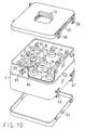
- Figure 10 shows, in perspective, exploded view an embodiment which does not give-off the above functional capabilities, provides some simplification, the maximum achievable compactness and further enhances the safety of the equipment.
- the manifold/distributor assembly comprises a frame 1 forming a substantially rectangular box with bottom and top faces closed bu removable upper and lower covers 64 and 65 respectively.
- the upper and lower covers are tightly coupled to the box by suitable gaskets (preferably O-Rings) not shown, and by retaining hooks, such as 66,67,68,69, manually operated for their hooking or release.
- suitable gaskets preferably O-Rings
- retaining hooks such as 66,67,68,69, manually operated for their hooking or release.
- the upper cover is expediently provided with a handle 72.
- the frame 1 forms a plurality of internal emispherical caps, such as 70, each for housing and guiding the head of a cartridge to an actuation valve assembly, such as 71, similar to those already described with reference to figures 2 and 9 and discussed more in detail in the following.
- the output of the several valve assemblies which preferably comprise also a non-return valve, are coupled together by two sets of connection pipes 73,74 and 75,76,77,78,79 respectively which form two portions of a manifold.
- the two sets are in turn copled to a multiple-way manually operated tap (a four way tap in particular) which establishes a selective fluid connection among them and a pressure/reducer regulator 81, whose output is in turn coupled-to a delivery pipe 82.
- the delivery pipe 82 preferably opens outside the box through a tight seal passage in the frame 1.
- An external actuation knob 83 having (in the example) four angular positions, actuates the multiple-way tap through a shaft 84 passing through a tight seal passage in the frame 1.
- the fluid connection may be established wit the delivery pipe 82 and the pressure regulator 81 may be a device external to the box and not an integral part of the equipment.
- Figure 11 is a diametrical section of one of the valve assemblies such as 71, of one of the caps, such as 70, and of a cartridge 85 coupled to the valve assembly 71.
- the cartridge is of the valve-type.
- the generally emispherical top 86 of the cartridge is housed in the cap 70, which serves as a guide for precisely aligning and orienting a screwed boss 87 of the top, relative to a screwed input recess of the valve assembly.
- shut-off valve 88 which may be opened by pushing inside the valve plug 89 with an actuation element which may be a pin, needle or plate of the valve assembly 71, depending on the design of the plug 89, which itself may be provided with a needle like actuator extending out of the boss.
- the valve assembly is very similar to the one already shown in figure 2 and comprises a spring biased, normally closed disc obturator 90 extending in an actuation needle 91.
- the cartridge valve When the cartridge boss is screwed in the recess of the valve assembly 71, the cartridge valve is opened and when fully opened the force exerted by the plug 89 on the needle 91 overcomes the bias applied to the disc obturator, which opens and establishes a fluid connection between the cartridge and the manifold.
- the gasket inherent in the cartridge valve which also interacts with the actuation needle 91, prevents any gas leakage but, if desired, for enhanced safety, an additional resilient gasket may be provided between the boss head and the bottom of the screwed input recess of the valve assembly.
- the valve assembly 71 provides for a non-return valve, of conventional structure, and consisting for instance in a floating ball 92, biased against a seat of the valve assembly by an overpressure at the valve assembly output relative to the input and driven away from the seat by a pressure at the input slightly exceeding the one at the output.
- the non-return valve may be a substitute for the actuation valve and a steady actuation element may be provided which interferes with the plug of the cartridge valve and opens it.
- the output of the valve assembly is connected to one (or more) of the pipes forming a manifold portion.
- the cartridge 85 may be a standard cartridge available on the market, but preferably, as shown in fig 11 it is modified to have a concave bottom 93 with a diameter substantially lesser (e.g 20-40 mm) than the cartidge diameter (which for a standard commercially available cartridge is 86 mm) surrounded by a concave toroidal crown 94.
- the bottom may be formed integral to the peripheral wall of the cartridge, as shown in the left side of figure 11, or formed as a severed element which is coupled to the peripheral wall by curling, in a well established manner, as shown in the right side of figure 11.
- the cartridges can therefore be arranged in the frame very tightly, without hampering their operability, thus minimizing the size of the frame.
- the pressure reducer/regulator preferably constitutes a part of the distributor assembly which has been described, it may alternatively constitute an integral part of the consumer appliance and may be integral with a supply tube of the appliance to which the distributor assembly is connected.
- the embodiment of figures 10,11 may be further provided, owing to the fact that the frame, when closed by the upper and lower cover forms a leaktight box or container, where possible gas leakage may be confined, with devices tailored to different applications.
- the leaktight box 95 when used indoor, may be provided with a vent pipe 96 for conveying any possible gas leakage from the equipment to the outside environment.
- vent pipe 96. directed outside the the compartment, through the compartment door resilient gasket (or any suitable opening) fits this purpose.
- the delivery pipe 82 may be closed by a plug.
- the knob 83 which is preferably removable from the actuation shaft, when set in the shut-off position me be removed, to avoid any casual switching of the multiple way tap in an open position.
- knob lock may be provided.
- the box or container 95 may be provided with acustic signalling devices, such as a buzzer or whistle 97, actuated bu the gas flowing out of the box through the vent pipe 96.
- acustic signalling devices such as a buzzer or whistle 97
- a visual indication may be provided too and may consist in an inflatable element, swollen by the overpressure developed by the gas leakage inside the container, such as for instance a closed end helicoidal tube which takes a straight form, for a predetermined internal overpressure.
Landscapes
- Engineering & Computer Science (AREA)
- Mechanical Engineering (AREA)
- General Engineering & Computer Science (AREA)
- Chemical & Material Sciences (AREA)
- Combustion & Propulsion (AREA)
- Filling Or Discharging Of Gas Storage Vessels (AREA)
- Hydrogen, Water And Hydrids (AREA)
- Feeding, Discharge, Calcimining, Fusing, And Gas-Generation Devices (AREA)
Claims (9)
- Rohrverteileranordnung (100) für brennbares Gas, das von mehreren Flüssiggaspatronen (36) zugeführt wird, aufweisenddadurch gekennzeichnet, daß sie weiterhineinen Rahmen (1), der mehrere Gehäuse (2, 3, 4, 5, 6, 7, 8, 9, 70) bildet, die jeweils ein offenes Ende zum Einsetzen einer der mehreren Flüssiggaspatronen (36, 85) und ein gegenüberliegendes Ende, das durch einen Hals (12) abgeschlossen ist, haben,mehrere Ventilanordnungen (13, 23, 30, 32, 71), in denen jeweils ein Betätigungselement (31, 91) enthalten ist, wobei jede Ventilanordnung auf dem Hals (12) eines der Gehäuse befestigt ist und einen Einlaß zu der Ventilanordnung von dem Betätigungselement und einen Auslaß hat,mehrere Mittel (21, 46, 49, 50, 51, 52, 54, 87), die jeweils zum Ausführen einer relativen Verschiebung zwischen einer Patrone (36, 85), die in einem der Gehäuse angeordnet ist, und dem Betätigungselement der zugehörigen Ventilanordnung, die am Hals dieses Gehäuses befestigt ist, in axialer Richtung des Betätigungselements dienen, wobei die relative Verschiebung eine Fluidverbindung zwischen der Patrone und der zugehörigen Ventilanordnung schafft und die Ventilanordnung öffnet, vorausgesetzt, daß die Patrone vorhanden ist,einen Rohrverteiler (15, 16, 17, 18, 73, 74, 75, 76, 77, 78, 79), der mit dem Auslaß der mehreren Ventilanordnungen und mit einem Verteilerrohr (20, 82) verbunden ist,manuell betätigbare Absperreinrichtungen (14, 80) im Rohrverteiler aufweist, die unabhängig auf den Ventilanordnungen zum selektiven Verbinden des Ausgangs der Ventilanordnungen mit dem Verteilerrohr über den Rohrverteiler betätigbar sind, wobei die Absperreinrichtungen (14, 80) einen Mehrweg-Absperrhahn (80) zum selektiven Steuern der Fluidverbindung zwischen Abschnitten (73, 74, 75, 76, 77, 78, 79) des Rohrverteilers und dem Verteilerrohr (82) aufweisen.
- Rohrverteileranordnung nach Anspruch 1, weiterhin aufweisend einen Druckregler (81), der zwischen dem Mehrweg-Absperrhahn (80) und dem Verteilerrohr (82) angeordnet ist.
- Rohrverteileranordnung nach Anspruch 1, beinhaltend mehrere Patronen (85), wobei die Patronen (85) von einem Ventiltyp mit einer Gewindenabe (87) sind, in der ein Patronen-Absperrventil (88) mit einem verschiebbaren Stöpsel (89) angeordnet ist, und wobei die mehreren Mittel zum Ausführen der relativen Verschiebung jeweils die Gewindenabe (87) und eine mit einem Gewinde versehene Ausnehmung der Ventilanordnungen, in der die Gewindenabe eingeschraubt werden kann, aufweisen.
- Rohrverteileranordnung nach Anspruch 3, bei der das Betätigungselement (91) infolge des Zusammenstoßens mit einem Ventilstöpsel (89) eines Patronen-Absperrventils (88) von einer ersten in eine zweite Position bewegbar ist, wobei das Betätigungselement, wenn es sich in der ersten Position befindet, die Ventilanordnung, in der es angeordnet ist, schließt, und, wenn es sich in der zweiten Position befindet, die Ventilanordnung und das Patronen-Absperrventil (88) öffnet.
- Rohrverteileranordnung nach Anspruch 4, bei der die Ventilanordnungen jeweils ein Druckdifferenzgesteuertes Rückschlagventil (92) aufweisen, das hinter einer Dichtung (90) angeordnet ist, die sich in das Betätigungselement (91) erstreckt.
- Rohrverteileranordnung nach Anspruch 1, bei der der Rahmen (1), der durch einen oberen und einen unteren Deckel (65, 64) abgeschlossen ist, ein lecksicheres Gehäuse bildet.
- Rohrverteileranordnung nach Anspruch 6, bei der das lecksichere Gehäuse ein Abzugsrohr (96) aufweist.
- Rohrverteileranordnung nach Anspruch 6, bei der das lecksichere Gehäuse eine Gasleck-Signalisierungsmittel (97) aufweist.
- Rohrverteileranordnung nach einen der vorhergehenden Ansprüche, umfassend mehrere Patronen (85), wobei jede Patrone einen zylindrischen Körper mit einer konkaven Unterseite (93) mit einem Durchmesser aufweist, der wesentlich geringer ist, von etwa 20mm bis etwa 40mm, als der Durchmesser des zylindrischen Körpers, und von einer konkaven ringförmigen Torodialkrone (94) umgeben ist.
Priority Applications (2)
| Application Number | Priority Date | Filing Date | Title |
|---|---|---|---|
| SI9730215T SI0900348T1 (en) | 1996-05-03 | 1997-04-18 | Manifold/distributor assembly for combustible gas supplied from a plurality of liquefied-gas cartridges |
| EP97921657A EP0900348B1 (de) | 1996-05-03 | 1997-04-18 | Verteiler für aus mehreren flüssiggaspatronen stammendes brenngas |
Applications Claiming Priority (4)
| Application Number | Priority Date | Filing Date | Title |
|---|---|---|---|
| EP96830258A EP0805302A1 (de) | 1996-05-03 | 1996-05-03 | Verteiler für aus mehreren Flüssiggaspatronen stammendes Brenngas |
| EP96830258 | 1996-05-03 | ||
| PCT/EP1997/001947 WO1997042446A1 (en) | 1996-05-03 | 1997-04-18 | Manifold/distributor assembly for combustible gas supplied from a plurality of liquefied-gas cartridges |
| EP97921657A EP0900348B1 (de) | 1996-05-03 | 1997-04-18 | Verteiler für aus mehreren flüssiggaspatronen stammendes brenngas |
Publications (2)
| Publication Number | Publication Date |
|---|---|
| EP0900348A1 EP0900348A1 (de) | 1999-03-10 |
| EP0900348B1 true EP0900348B1 (de) | 2002-01-09 |
Family
ID=8225899
Family Applications (2)
| Application Number | Title | Priority Date | Filing Date |
|---|---|---|---|
| EP96830258A Withdrawn EP0805302A1 (de) | 1996-05-03 | 1996-05-03 | Verteiler für aus mehreren Flüssiggaspatronen stammendes Brenngas |
| EP97921657A Expired - Lifetime EP0900348B1 (de) | 1996-05-03 | 1997-04-18 | Verteiler für aus mehreren flüssiggaspatronen stammendes brenngas |
Family Applications Before (1)
| Application Number | Title | Priority Date | Filing Date |
|---|---|---|---|
| EP96830258A Withdrawn EP0805302A1 (de) | 1996-05-03 | 1996-05-03 | Verteiler für aus mehreren Flüssiggaspatronen stammendes Brenngas |
Country Status (16)
| Country | Link |
|---|---|
| US (1) | US6196255B1 (de) |
| EP (2) | EP0805302A1 (de) |
| JP (1) | JP2000510221A (de) |
| CN (1) | CN1089878C (de) |
| AT (1) | ATE211808T1 (de) |
| AU (1) | AU723111B2 (de) |
| BR (1) | BR9709208A (de) |
| DE (1) | DE69709920T2 (de) |
| DK (1) | DK0900348T3 (de) |
| ES (1) | ES2169862T3 (de) |
| PT (1) | PT900348E (de) |
| RU (1) | RU2190801C2 (de) |
| SI (1) | SI0900348T1 (de) |
| TR (1) | TR199802210T2 (de) |
| WO (1) | WO1997042446A1 (de) |
| YU (1) | YU49332B (de) |
Cited By (1)
| Publication number | Priority date | Publication date | Assignee | Title |
|---|---|---|---|---|
| CN110779052A (zh) * | 2019-11-06 | 2020-02-11 | 沈良国 | 一种节能燃气灶 |
Families Citing this family (42)
| Publication number | Priority date | Publication date | Assignee | Title |
|---|---|---|---|---|
| DE19812904C2 (de) * | 1998-03-18 | 2000-02-03 | Mannesmann Ag | Vorrichtung zum Speichern von Druckgas |
| US6386384B1 (en) | 2000-02-09 | 2002-05-14 | Amtrol, Inc. | Full jacket gas cylinder |
| ATE366389T1 (de) * | 2000-02-09 | 2007-07-15 | Amtrol Inc | Volle auskleidung für gaszylinder |
| SI1315933T1 (en) * | 2000-08-31 | 2005-04-30 | Walter Tosto Serbatoi S.P.A. | Combustible gas distribution apparatus |
| NL1018674C2 (nl) * | 2001-07-31 | 2003-02-03 | Wilde Internat De | Inrichting voor het opslaan en leveren van een onder druk staand fluïdum. |
| JP2003276456A (ja) * | 2002-03-22 | 2003-09-30 | Honda Motor Co Ltd | 燃料タンク構造 |
| US6772918B2 (en) * | 2002-10-07 | 2004-08-10 | Justrite Manufacturing Company | Safety can |
| US6941938B2 (en) * | 2002-12-10 | 2005-09-13 | Crossman Corporation | Adapter assembly with floating pin for operably connecting pressurized bottle to a paintball marker |
| US7810669B2 (en) * | 2004-03-05 | 2010-10-12 | Airbus Deutschland Gmbh | Replaceable cartridge for liquid hydrogen |
| DE102004010937B4 (de) * | 2004-03-05 | 2006-03-23 | Airbus Deutschland Gmbh | Wechselkartusche für Flüssigwasserstoff |
| US7624753B2 (en) * | 2004-08-10 | 2009-12-01 | Gm Global Technology Operations, Inc. | Container for gas storage tanks in a vehicle |
| JP4602721B2 (ja) * | 2004-09-10 | 2010-12-22 | アネスト岩田株式会社 | 圧縮気体装置 |
| DE102005022646A1 (de) * | 2005-05-11 | 2006-11-23 | Erwin Weh | Anschlusskupplung für einen Fluidbehälter und damit gebildetes Flaschenwechselsystem |
| ITMC20060074A1 (it) * | 2006-06-13 | 2007-12-14 | Sida Engineering Srl | Serbatoio multi-celle, perfezionato, per gas in pressione. |
| RU2349248C2 (ru) * | 2007-08-16 | 2009-03-20 | Леонид Федорович Порядков | Кислородная палочка |
| US8499789B2 (en) * | 2008-05-29 | 2013-08-06 | Tescom Corporation | Mobile gas supply system |
| FR2942863B1 (fr) * | 2009-03-03 | 2013-04-19 | Guilbert Express Sa | Cartouche perforable anti-fuite. |
| FR2955569B1 (fr) * | 2010-01-28 | 2012-01-20 | Arkema France | Dispositif constitue de futs connectes destine au transport de matieres dangereuses |
| FR2956185B1 (fr) * | 2010-02-11 | 2012-05-04 | Air Liquide | Reservoir composite et ensemble comprenant un tel reservoir et un organe receveur et/ou distributeur de gaz |
| CA2791993C (en) | 2010-03-01 | 2018-08-28 | Justrite Manufacturing Company Llc | Safety can |
| DE102011014065A1 (de) * | 2011-03-16 | 2012-09-20 | Messer Gaspack Gmbh | Anordnung zum Speichern und Entnehmen von komprimiertem Gas |
| CN102980032B (zh) * | 2012-11-28 | 2015-04-15 | 北京天海工业有限公司 | 外胆前封头上的充液装置 |
| FR3020442B1 (fr) * | 2014-04-24 | 2017-02-17 | Air Liquide | Dispositif de fourniture de gaz |
| JP6307622B2 (ja) * | 2014-09-05 | 2018-04-04 | 株式会社日立ハイテクノロジーズ | 電子線装置および電子線装置用ガス供給装置 |
| US9616798B2 (en) * | 2015-01-28 | 2017-04-11 | Fuelie Systems, Inc. | Portable fuel storage device |
| EP3086018A1 (de) * | 2015-04-20 | 2016-10-26 | Linde Aktiengesellschaft | Zylinderexklusivverbindung |
| US9593905B2 (en) * | 2015-04-21 | 2017-03-14 | Jui-Fu Tseng | Pull ring for air container of airsoft gun |
| FR3040757B1 (fr) * | 2015-09-04 | 2018-05-11 | L'air Liquide, Societe Anonyme Pour L'etude Et L’Exploitation Des Procedes Georges Claude | Cassette de stockage pour bouteilles a fluide sous pression et un cadre de stockage associe |
| CN105351597B (zh) * | 2015-12-09 | 2017-12-22 | 浙江信达可恩消防实业有限责任公司 | 用于气体灭火系统在线检测的启动装置 |
| JP5980406B1 (ja) * | 2015-12-29 | 2016-08-31 | 株式会社フーズアイ | バーベキューグリルおよびバーベキューグリルを用いた調理方法 |
| US10458600B2 (en) * | 2016-04-08 | 2019-10-29 | Hexagon Technology As | System with remotely controlled, pressure actuated tank valve |
| GB2552781A (en) * | 2016-08-01 | 2018-02-14 | Linde Aktiengesellshcaft | A galleried manifold for a bundle of high pressure gas cylinders |
| CN108016570B (zh) * | 2016-10-28 | 2024-02-27 | 石家庄安瑞科气体机械有限公司 | Cng运输船气瓶或瓶式容器编组单元的密封装置及编组单元 |
| CN107218507A (zh) * | 2017-07-17 | 2017-09-29 | 力合科技(湖南)股份有限公司 | 一种供气设备及移动实验室 |
| JP6794959B2 (ja) * | 2017-08-09 | 2020-12-02 | トヨタ自動車株式会社 | 高圧容器ユニット |
| US11840444B2 (en) | 2018-03-16 | 2023-12-12 | Fuelie Systems, Inc. | Fuel storage and dispensing device |
| KR102279485B1 (ko) * | 2020-02-28 | 2021-07-19 | 김주학 | 휴대용 가스용기 연결장치 |
| US12420631B2 (en) * | 2020-03-24 | 2025-09-23 | Toyota Jidosha Kabushiki Kaisha | Fuel tank |
| DE102021130250A1 (de) * | 2021-11-19 | 2023-05-25 | Bayerische Motoren Werke Aktiengesellschaft | Ventilbaugruppe, Druckbehältersystem, Fahrzeug und Verfahren zum Ablassen von Brennstoff |
| US11877658B2 (en) * | 2022-06-07 | 2024-01-23 | Ratermann Manufacturing, Inc. | Gas cylinder tank storage rack with method of signaling tank inventory |
| US20250389385A1 (en) * | 2024-06-21 | 2025-12-25 | Braindrip, Llc | Gigavault facilities with tubular composite sealed vessels for storage of media |
| US20260063245A1 (en) * | 2024-08-30 | 2026-03-05 | Ignik Outdoors, Inc. | Refueling assemblies for fuel tanks, refillable fuel tanks, and associated methods |
Family Cites Families (13)
| Publication number | Priority date | Publication date | Assignee | Title |
|---|---|---|---|---|
| US3161322A (en) * | 1961-10-11 | 1964-12-15 | Clive H Bramson | Pocket gas dispenser |
| GB1122864A (en) * | 1966-05-03 | 1968-08-07 | Kidde Walter Co Ltd | Improvements in or relating to inflators, particularly for life jackets |
| FR1503773A (fr) * | 1966-10-05 | 1967-12-01 | Applic Gaz Sa | Perfectionnements aux dispositifs pour la fixation de réservoirs ou de cartouches contenant notamment un gaz combustible liquéfié sous pression |
| FR2076256A5 (de) * | 1970-01-06 | 1971-10-15 | Zwilling Jacques | |
| US3930598A (en) * | 1974-03-28 | 1976-01-06 | Bildon Company | Liquid dispensing apparatus |
| DE2650880C2 (de) * | 1976-11-06 | 1986-04-03 | Linde Ag, 6200 Wiesbaden | Vorrichtung zur Entnahme von Gasen aus Flaschen |
| FR2497706A1 (fr) * | 1981-01-12 | 1982-07-16 | Air Liquide | Poste a deux ou plusieurs bouteilles de gaz pour le soudage et autres applications |
| US4461271A (en) * | 1982-04-21 | 1984-07-24 | Juang Bor L | Portable gas firing apparatus |
| CH663835A5 (de) * | 1984-03-02 | 1988-01-15 | Pewa Technic Ag | Gasversorgungseinrichtung mit mehreren in einen druckgasbehaelter eingesetzten gasflaschen. |
| US4967934A (en) * | 1988-06-07 | 1990-11-06 | Andonian Martin D | Pack of high pressure gas containers |
| FR2642142B1 (fr) * | 1989-01-20 | 1991-06-07 | Butagaz | Conditionnement compact pour gaz de petrole liquefies |
| GB2262156B (en) | 1991-12-04 | 1995-08-30 | Taymar Ltd | A valve |
| FR2734341B1 (fr) | 1995-05-18 | 1997-06-20 | Taema | Installation de fourniture de gaz sous basse pression |
-
1996
- 1996-05-03 EP EP96830258A patent/EP0805302A1/de not_active Withdrawn
-
1997
- 1997-04-18 BR BR9709208-8A patent/BR9709208A/pt not_active IP Right Cessation
- 1997-04-18 ES ES97921657T patent/ES2169862T3/es not_active Expired - Lifetime
- 1997-04-18 CN CN97194361A patent/CN1089878C/zh not_active Expired - Fee Related
- 1997-04-18 PT PT97921657T patent/PT900348E/pt unknown
- 1997-04-18 YU YU49498A patent/YU49332B/sh unknown
- 1997-04-18 DE DE69709920T patent/DE69709920T2/de not_active Expired - Fee Related
- 1997-04-18 EP EP97921657A patent/EP0900348B1/de not_active Expired - Lifetime
- 1997-04-18 US US09/180,248 patent/US6196255B1/en not_active Expired - Fee Related
- 1997-04-18 TR TR1998/02210T patent/TR199802210T2/xx unknown
- 1997-04-18 WO PCT/EP1997/001947 patent/WO1997042446A1/en not_active Ceased
- 1997-04-18 DK DK97921657T patent/DK0900348T3/da active
- 1997-04-18 RU RU98121811/12A patent/RU2190801C2/ru not_active IP Right Cessation
- 1997-04-18 JP JP09539466A patent/JP2000510221A/ja not_active Ceased
- 1997-04-18 AT AT97921657T patent/ATE211808T1/de not_active IP Right Cessation
- 1997-04-18 AU AU27654/97A patent/AU723111B2/en not_active Ceased
- 1997-04-18 SI SI9730215T patent/SI0900348T1/xx unknown
Cited By (2)
| Publication number | Priority date | Publication date | Assignee | Title |
|---|---|---|---|---|
| CN110779052A (zh) * | 2019-11-06 | 2020-02-11 | 沈良国 | 一种节能燃气灶 |
| CN110779052B (zh) * | 2019-11-06 | 2021-11-30 | 北京中天白云厨房设备有限公司 | 一种节能燃气灶 |
Also Published As
| Publication number | Publication date |
|---|---|
| AU723111B2 (en) | 2000-08-17 |
| WO1997042446A1 (en) | 1997-11-13 |
| EP0805302A1 (de) | 1997-11-05 |
| DE69709920T2 (de) | 2002-08-22 |
| ES2169862T3 (es) | 2002-07-16 |
| DK0900348T3 (da) | 2002-03-25 |
| SI0900348T1 (en) | 2002-04-30 |
| PT900348E (pt) | 2002-05-31 |
| DE69709920D1 (de) | 2002-02-28 |
| ATE211808T1 (de) | 2002-01-15 |
| YU49332B (sh) | 2005-07-19 |
| TR199802210T2 (xx) | 1999-02-22 |
| JP2000510221A (ja) | 2000-08-08 |
| AU2765497A (en) | 1997-11-26 |
| US6196255B1 (en) | 2001-03-06 |
| BR9709208A (pt) | 2000-12-12 |
| CN1217773A (zh) | 1999-05-26 |
| YU49498A (sh) | 2000-03-21 |
| CN1089878C (zh) | 2002-08-28 |
| RU2190801C2 (ru) | 2002-10-10 |
| EP0900348A1 (de) | 1999-03-10 |
Similar Documents
| Publication | Publication Date | Title |
|---|---|---|
| US6196255B1 (en) | Manifold/distributor assembly for combustible gas supplied from a plurality of liquefied-gas cartridges | |
| CN101297151B (zh) | 包括加压气体储存容器和用气体灌装所述容器和/或从所述容器中取出气体的控制装置的组件 | |
| CN101297152B (zh) | 流体填充和/或提取控制装置和包括一个该装置的容器 | |
| US4363424A (en) | Quick coupling device for a gas pressurization system | |
| US5894869A (en) | CO2 cartridge pressurization device | |
| GB2073853A (en) | Safety pressure reducing regulator | |
| NZ293557A (en) | Pressure cylinder connection arrangement with check valve operated by valve tappet and connecting device pivoting about axis transverse to cylinder axis | |
| EP0866937B1 (de) | Butangerät mit druckbehälter | |
| US3361298A (en) | Camping unit fuel tank filler spout cap assembly | |
| US3731718A (en) | Adapter connector | |
| CA2351263C (en) | Tank for gaseous fuels with additional internal reservoir | |
| JPH0242491B2 (de) | ||
| US4181493A (en) | Gas lighter having slidably detachable head assembly | |
| CA2253558C (en) | Manifold/distributor assembly for combustible gas supplied from a plurality of liquefied-gas cartridges | |
| KR20010029430A (ko) | 교체 가스연료의 사용을 위한 어댑터 | |
| GB2112124A (en) | Gas cylinder fitting | |
| EP1722139B1 (de) | Kegelventil für flüssiggasbehälter | |
| US3626476A (en) | Fuel tank pressurizer | |
| KR100235234B1 (ko) | 액화가스용기용 개폐밸브의 안전장치 | |
| US2592259A (en) | Automatic selector, change-over regulator and indicator device | |
| US2886055A (en) | Dispenser for liquid petroleum gas | |
| US20110114644A1 (en) | Pressure release button and tool for propane cylinders | |
| US2664727A (en) | Self-sealing tank to contain gas under pressure | |
| JP2524873Y2 (ja) | ガス容器の容器弁 | |
| KR200149488Y1 (ko) | 역류방지 기능을 갖는 가스집합장치 |
Legal Events
| Date | Code | Title | Description |
|---|---|---|---|
| PUAI | Public reference made under article 153(3) epc to a published international application that has entered the european phase |
Free format text: ORIGINAL CODE: 0009012 |
|
| 17P | Request for examination filed |
Effective date: 19981102 |
|
| AK | Designated contracting states |
Kind code of ref document: A1 Designated state(s): AT BE CH DE DK ES FI FR GB GR IE IT LI LU MC NL PT SE |
|
| AX | Request for extension of the european patent |
Free format text: RO PAYMENT 981102;SI PAYMENT 981102 |
|
| RAP1 | Party data changed (applicant data changed or rights of an application transferred) |
Owner name: WALTER TOSTO SERBATOI S.P.A. |
|
| GRAG | Despatch of communication of intention to grant |
Free format text: ORIGINAL CODE: EPIDOS AGRA |
|
| GRAG | Despatch of communication of intention to grant |
Free format text: ORIGINAL CODE: EPIDOS AGRA |
|
| GRAH | Despatch of communication of intention to grant a patent |
Free format text: ORIGINAL CODE: EPIDOS IGRA |
|
| 17Q | First examination report despatched |
Effective date: 20010521 |
|
| GRAH | Despatch of communication of intention to grant a patent |
Free format text: ORIGINAL CODE: EPIDOS IGRA |
|
| GRAA | (expected) grant |
Free format text: ORIGINAL CODE: 0009210 |
|
| REG | Reference to a national code |
Ref country code: GB Ref legal event code: IF02 |
|
| AK | Designated contracting states |
Kind code of ref document: B1 Designated state(s): AT BE CH DE DK ES FI FR GB GR IE IT LI LU MC NL PT SE |
|
| AX | Request for extension of the european patent |
Free format text: RO PAYMENT 19981102;SI PAYMENT 19981102 |
|
| REF | Corresponds to: |
Ref document number: 211808 Country of ref document: AT Date of ref document: 20020115 Kind code of ref document: T |
|
| REG | Reference to a national code |
Ref country code: CH Ref legal event code: EP |
|
| REG | Reference to a national code |
Ref country code: IE Ref legal event code: FG4D |
|
| REG | Reference to a national code |
Ref country code: CH Ref legal event code: NV Representative=s name: JACOBACCI & PARTNERS S.P.A. |
|
| REF | Corresponds to: |
Ref document number: 69709920 Country of ref document: DE Date of ref document: 20020228 |
|
| REG | Reference to a national code |
Ref country code: DK Ref legal event code: T3 |
|
| REG | Reference to a national code |
Ref country code: PT Ref legal event code: SC4A Free format text: AVAILABILITY OF NATIONAL TRANSLATION Effective date: 20020110 |
|
| ET | Fr: translation filed | ||
| REG | Reference to a national code |
Ref country code: ES Ref legal event code: FG2A Ref document number: 2169862 Country of ref document: ES Kind code of ref document: T3 |
|
| REG | Reference to a national code |
Ref country code: GR Ref legal event code: EP Ref document number: 20020401107 Country of ref document: GR |
|
| PLBE | No opposition filed within time limit |
Free format text: ORIGINAL CODE: 0009261 |
|
| STAA | Information on the status of an ep patent application or granted ep patent |
Free format text: STATUS: NO OPPOSITION FILED WITHIN TIME LIMIT |
|
| 26N | No opposition filed | ||
| REG | Reference to a national code |
Ref country code: SI Ref legal event code: IF |
|
| PGFP | Annual fee paid to national office [announced via postgrant information from national office to epo] |
Ref country code: AT Payment date: 20070308 Year of fee payment: 11 |
|
| PGFP | Annual fee paid to national office [announced via postgrant information from national office to epo] |
Ref country code: NL Payment date: 20070315 Year of fee payment: 11 Ref country code: DK Payment date: 20070315 Year of fee payment: 11 Ref country code: IE Payment date: 20070315 Year of fee payment: 11 Ref country code: GB Payment date: 20070315 Year of fee payment: 11 |
|
| PGFP | Annual fee paid to national office [announced via postgrant information from national office to epo] |
Ref country code: FI Payment date: 20070316 Year of fee payment: 11 |
|
| PGFP | Annual fee paid to national office [announced via postgrant information from national office to epo] |
Ref country code: PT Payment date: 20070321 Year of fee payment: 11 |
|
| PGFP | Annual fee paid to national office [announced via postgrant information from national office to epo] |
Ref country code: MC Payment date: 20070323 Year of fee payment: 11 Ref country code: ES Payment date: 20070323 Year of fee payment: 11 |
|
| PGFP | Annual fee paid to national office [announced via postgrant information from national office to epo] |
Ref country code: DE Payment date: 20070326 Year of fee payment: 11 Ref country code: LU Payment date: 20070326 Year of fee payment: 11 |
|
| PGFP | Annual fee paid to national office [announced via postgrant information from national office to epo] |
Ref country code: SE Payment date: 20070329 Year of fee payment: 11 |
|
| PGFP | Annual fee paid to national office [announced via postgrant information from national office to epo] |
Ref country code: BE Payment date: 20070330 Year of fee payment: 11 |
|
| PGFP | Annual fee paid to national office [announced via postgrant information from national office to epo] |
Ref country code: CH Payment date: 20070425 Year of fee payment: 11 |
|
| PGFP | Annual fee paid to national office [announced via postgrant information from national office to epo] |
Ref country code: GR Payment date: 20070323 Year of fee payment: 11 |
|
| PGFP | Annual fee paid to national office [announced via postgrant information from national office to epo] |
Ref country code: FR Payment date: 20070430 Year of fee payment: 11 |
|
| BERE | Be: lapsed |
Owner name: WALTER *TOSTO SERBATOI S.P.A. Effective date: 20080430 |
|
| REG | Reference to a national code |
Ref country code: PT Ref legal event code: MM4A Free format text: LAPSE DUE TO NON-PAYMENT OF FEES Effective date: 20081020 |
|
| PG25 | Lapsed in a contracting state [announced via postgrant information from national office to epo] |
Ref country code: MC Free format text: LAPSE BECAUSE OF NON-PAYMENT OF DUE FEES Effective date: 20080430 |
|
| REG | Reference to a national code |
Ref country code: CH Ref legal event code: PL |
|
| REG | Reference to a national code |
Ref country code: DK Ref legal event code: EBP |
|
| EUG | Se: european patent has lapsed | ||
| GBPC | Gb: european patent ceased through non-payment of renewal fee |
Effective date: 20080418 |
|
| NLV4 | Nl: lapsed or anulled due to non-payment of the annual fee |
Effective date: 20081101 |
|
| REG | Reference to a national code |
Ref country code: IE Ref legal event code: MM4A |
|
| PG25 | Lapsed in a contracting state [announced via postgrant information from national office to epo] |
Ref country code: PT Free format text: LAPSE BECAUSE OF NON-PAYMENT OF DUE FEES Effective date: 20081020 Ref country code: NL Free format text: LAPSE BECAUSE OF NON-PAYMENT OF DUE FEES Effective date: 20081101 Ref country code: LI Free format text: LAPSE BECAUSE OF NON-PAYMENT OF DUE FEES Effective date: 20080430 Ref country code: DE Free format text: LAPSE BECAUSE OF NON-PAYMENT OF DUE FEES Effective date: 20081101 Ref country code: CH Free format text: LAPSE BECAUSE OF NON-PAYMENT OF DUE FEES Effective date: 20080430 |
|
| REG | Reference to a national code |
Ref country code: FR Ref legal event code: ST Effective date: 20081231 |
|
| PG25 | Lapsed in a contracting state [announced via postgrant information from national office to epo] |
Ref country code: FI Free format text: LAPSE BECAUSE OF NON-PAYMENT OF DUE FEES Effective date: 20080418 Ref country code: AT Free format text: LAPSE BECAUSE OF NON-PAYMENT OF DUE FEES Effective date: 20080418 |
|
| REG | Reference to a national code |
Ref country code: SI Ref legal event code: KO00 Effective date: 20081208 |
|
| PG25 | Lapsed in a contracting state [announced via postgrant information from national office to epo] |
Ref country code: BE Free format text: LAPSE BECAUSE OF NON-PAYMENT OF DUE FEES Effective date: 20080430 |
|
| PG25 | Lapsed in a contracting state [announced via postgrant information from national office to epo] |
Ref country code: IE Free format text: LAPSE BECAUSE OF NON-PAYMENT OF DUE FEES Effective date: 20080418 Ref country code: FR Free format text: LAPSE BECAUSE OF NON-PAYMENT OF DUE FEES Effective date: 20080430 Ref country code: DK Free format text: LAPSE BECAUSE OF NON-PAYMENT OF DUE FEES Effective date: 20080430 |
|
| REG | Reference to a national code |
Ref country code: ES Ref legal event code: FD2A Effective date: 20080419 |
|
| PG25 | Lapsed in a contracting state [announced via postgrant information from national office to epo] |
Ref country code: GR Free format text: LAPSE BECAUSE OF NON-PAYMENT OF DUE FEES Effective date: 20081104 Ref country code: GB Free format text: LAPSE BECAUSE OF NON-PAYMENT OF DUE FEES Effective date: 20080418 |
|
| PG25 | Lapsed in a contracting state [announced via postgrant information from national office to epo] |
Ref country code: ES Free format text: LAPSE BECAUSE OF NON-PAYMENT OF DUE FEES Effective date: 20080419 |
|
| PG25 | Lapsed in a contracting state [announced via postgrant information from national office to epo] |
Ref country code: LU Free format text: LAPSE BECAUSE OF NON-PAYMENT OF DUE FEES Effective date: 20080418 |
|
| PG25 | Lapsed in a contracting state [announced via postgrant information from national office to epo] |
Ref country code: SE Free format text: LAPSE BECAUSE OF NON-PAYMENT OF DUE FEES Effective date: 20080419 |
|
| PGFP | Annual fee paid to national office [announced via postgrant information from national office to epo] |
Ref country code: IT Payment date: 20160408 Year of fee payment: 20 |