EP0900649A2 - Matelas en fibres de verre renforcé et méthode de fabrication - Google Patents
Matelas en fibres de verre renforcé et méthode de fabrication Download PDFInfo
- Publication number
- EP0900649A2 EP0900649A2 EP98307109A EP98307109A EP0900649A2 EP 0900649 A2 EP0900649 A2 EP 0900649A2 EP 98307109 A EP98307109 A EP 98307109A EP 98307109 A EP98307109 A EP 98307109A EP 0900649 A2 EP0900649 A2 EP 0900649A2
- Authority
- EP
- European Patent Office
- Prior art keywords
- binder
- mat
- glass fiber
- glass fibers
- concentration
- Prior art date
- Legal status (The legal status is an assumption and is not a legal conclusion. Google has not performed a legal analysis and makes no representation as to the accuracy of the status listed.)
- Withdrawn
Links
Images

Classifications
-
- D—TEXTILES; PAPER
- D06—TREATMENT OF TEXTILES OR THE LIKE; LAUNDERING; FLEXIBLE MATERIALS NOT OTHERWISE PROVIDED FOR
- D06N—WALL, FLOOR, OR LIKE COVERING MATERIALS, e.g. LINOLEUM, OILCLOTH, ARTIFICIAL LEATHER, ROOFING FELT, CONSISTING OF A FIBROUS WEB COATED WITH A LAYER OF MACROMOLECULAR MATERIAL; FLEXIBLE SHEET MATERIAL NOT OTHERWISE PROVIDED FOR
- D06N5/00—Roofing materials comprising a fibrous web coated with bitumen or another polymer, e.g. pitch
-
- E—FIXED CONSTRUCTIONS
- E04—BUILDING
- E04D—ROOF COVERINGS; SKY-LIGHTS; GUTTERS; ROOF-WORKING TOOLS
- E04D5/00—Roof covering by making use of flexible material, e.g. supplied in roll form
- E04D5/02—Roof covering by making use of flexible material, e.g. supplied in roll form of materials impregnated with sealing substances, e.g. roofing felt
-
- Y—GENERAL TAGGING OF NEW TECHNOLOGICAL DEVELOPMENTS; GENERAL TAGGING OF CROSS-SECTIONAL TECHNOLOGIES SPANNING OVER SEVERAL SECTIONS OF THE IPC; TECHNICAL SUBJECTS COVERED BY FORMER USPC CROSS-REFERENCE ART COLLECTIONS [XRACs] AND DIGESTS
- Y10—TECHNICAL SUBJECTS COVERED BY FORMER USPC
- Y10S—TECHNICAL SUBJECTS COVERED BY FORMER USPC CROSS-REFERENCE ART COLLECTIONS [XRACs] AND DIGESTS
- Y10S83/00—Cutting
- Y10S83/92—Shingle making
-
- Y—GENERAL TAGGING OF NEW TECHNOLOGICAL DEVELOPMENTS; GENERAL TAGGING OF CROSS-SECTIONAL TECHNOLOGIES SPANNING OVER SEVERAL SECTIONS OF THE IPC; TECHNICAL SUBJECTS COVERED BY FORMER USPC CROSS-REFERENCE ART COLLECTIONS [XRACs] AND DIGESTS
- Y10—TECHNICAL SUBJECTS COVERED BY FORMER USPC
- Y10T—TECHNICAL SUBJECTS COVERED BY FORMER US CLASSIFICATION
- Y10T428/00—Stock material or miscellaneous articles
- Y10T428/31504—Composite [nonstructural laminate]
- Y10T428/31551—Of polyamidoester [polyurethane, polyisocyanate, polycarbamate, etc.]
- Y10T428/31627—Next to aldehyde or ketone condensation product
-
- Y—GENERAL TAGGING OF NEW TECHNOLOGICAL DEVELOPMENTS; GENERAL TAGGING OF CROSS-SECTIONAL TECHNOLOGIES SPANNING OVER SEVERAL SECTIONS OF THE IPC; TECHNICAL SUBJECTS COVERED BY FORMER USPC CROSS-REFERENCE ART COLLECTIONS [XRACs] AND DIGESTS
- Y10—TECHNICAL SUBJECTS COVERED BY FORMER USPC
- Y10T—TECHNICAL SUBJECTS COVERED BY FORMER US CLASSIFICATION
- Y10T428/00—Stock material or miscellaneous articles
- Y10T428/31504—Composite [nonstructural laminate]
- Y10T428/31551—Of polyamidoester [polyurethane, polyisocyanate, polycarbamate, etc.]
- Y10T428/31641—Next to natural rubber, gum, oil, rosin, wax, bituminous or tarry residue
-
- Y—GENERAL TAGGING OF NEW TECHNOLOGICAL DEVELOPMENTS; GENERAL TAGGING OF CROSS-SECTIONAL TECHNOLOGIES SPANNING OVER SEVERAL SECTIONS OF THE IPC; TECHNICAL SUBJECTS COVERED BY FORMER USPC CROSS-REFERENCE ART COLLECTIONS [XRACs] AND DIGESTS
- Y10—TECHNICAL SUBJECTS COVERED BY FORMER USPC
- Y10T—TECHNICAL SUBJECTS COVERED BY FORMER US CLASSIFICATION
- Y10T442/00—Fabric [woven, knitted, or nonwoven textile or cloth, etc.]
- Y10T442/20—Coated or impregnated woven, knit, or nonwoven fabric which is not [a] associated with another preformed layer or fiber layer or, [b] with respect to woven and knit, characterized, respectively, by a particular or differential weave or knit, wherein the coating or impregnation is neither a foamed material nor a free metal or alloy layer
- Y10T442/2926—Coated or impregnated inorganic fiber fabric
- Y10T442/2959—Coating or impregnation contains aldehyde or ketone condensation product
-
- Y—GENERAL TAGGING OF NEW TECHNOLOGICAL DEVELOPMENTS; GENERAL TAGGING OF CROSS-SECTIONAL TECHNOLOGIES SPANNING OVER SEVERAL SECTIONS OF THE IPC; TECHNICAL SUBJECTS COVERED BY FORMER USPC CROSS-REFERENCE ART COLLECTIONS [XRACs] AND DIGESTS
- Y10—TECHNICAL SUBJECTS COVERED BY FORMER USPC
- Y10T—TECHNICAL SUBJECTS COVERED BY FORMER US CLASSIFICATION
- Y10T442/00—Fabric [woven, knitted, or nonwoven textile or cloth, etc.]
- Y10T442/20—Coated or impregnated woven, knit, or nonwoven fabric which is not [a] associated with another preformed layer or fiber layer or, [b] with respect to woven and knit, characterized, respectively, by a particular or differential weave or knit, wherein the coating or impregnation is neither a foamed material nor a free metal or alloy layer
- Y10T442/2926—Coated or impregnated inorganic fiber fabric
- Y10T442/2992—Coated or impregnated glass fiber fabric
-
- Y—GENERAL TAGGING OF NEW TECHNOLOGICAL DEVELOPMENTS; GENERAL TAGGING OF CROSS-SECTIONAL TECHNOLOGIES SPANNING OVER SEVERAL SECTIONS OF THE IPC; TECHNICAL SUBJECTS COVERED BY FORMER USPC CROSS-REFERENCE ART COLLECTIONS [XRACs] AND DIGESTS
- Y10—TECHNICAL SUBJECTS COVERED BY FORMER USPC
- Y10T—TECHNICAL SUBJECTS COVERED BY FORMER US CLASSIFICATION
- Y10T442/00—Fabric [woven, knitted, or nonwoven textile or cloth, etc.]
- Y10T442/60—Nonwoven fabric [i.e., nonwoven strand or fiber material]
Definitions
- Asphalt roofing shingles are based on an interior web or carrier commonly formed as a glass fiber mat in a wet process.
- Shingle manufacturing consists of running a continuous wet process glass fiber mat in a bath of molten asphalt to cause a coating on both sides of the mat, as well as filling the interstices between the individual glass fibers.
- Wet process glass fiber mats are conventionally made from glass fibers held together by a binder comprising a thermoset polymer system.
- a binder is applied in a liquid form and dispersed onto the glass fibers through an applicator such as a curtain coater.
- Conventional wet processes strive to produce a uniform coating of binder on the glass fibers. After the binder and glass fibers have been dried and cured in an oven, the glass fiber mat is gauged and cut as desired.
- cuts are made in a glass fiber mat along the longitudinal length of the mat to produce several mats of a desired width.
- Each cutting operation produces side edges for each of the narrower mats.
- the cutting operation may expose or produce weaker areas in the mat along the side edges.
- the weakened mat edge can break during a coating process or result in a shingle having a weakened edge, i.e., an edge prone to tearing or breaking during handling or installation.
- Conventional techniques for reinforcing such edges include the addition of a yarn or tape to the desired portion of the glass fiber mat. The addition of such materials can increase the cost of manufacture of glass fiber mats.
- glass fiber mats It is desirable to improve the performance of glass fiber mats and prevent cut edges from exposing areas prone to breaking or tearing. Furthermore, it is desirable to produce glass fiber mats which produce shingles having increased tear strength and pliability.
- a glass fiber mat according to this invention includes a reinforced portion which provides additional tear strength and resistance to breaking along cut edges.
- the present reinforced glass fiber mat can be formed with conventional binders and does not require additional materials or additional process steps.
- Improved roofing shingles can be manufactured from the present glass fiber mat via conventional coating techniques.
- a glass fiber mat includes glass fibers saturated with a binder and then cured.
- a predetermined pattern of relatively high and low concentrations of binder is formed throughout the length of the glass fiber mat.
- the pattern produces at least one portion of the mat having a relatively high concentration of binder adjoining a portion of the mat having a relatively low concentration of binder.
- the pattern of high and low binder concentrations is produced during a binder saturation step of a wet process.
- Liquid binder is either selectively applied to the glass fibers via an applicator or selectively removed from the glass fibers via a vacuum. Cover panels having predetermined slot configurations are used with vacuum boxes to create the desired pattern.
- Such glass fiber mats can be cut through an area of high binder concentration to produce reinforced edges which resist breaking and tearing. Shingles formed from such glass fiber mats have improved tear resistance and pliability.
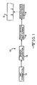
- FIG. 1 is a flow diagram of a four-step wet process for forming a glass fiber mat according to this invention.
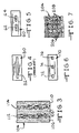
- FIG. 2 is a pictorial sketch of the binder saturation station of the process of FIG. 1 illustrating a tank containing liquid binder, a pump for delivering binder to an applicator, and vacuum boxes for removing excess binder.
- FIG. 3 is a top view of a first embodiment of a glass fiber mat according to this invention formed from the process illustrated in FIGS. 1 and 2.
- FIG. 4 is a top view of a prior art cover panel having a single slot for use with a vacuum box of FIG 2.
- FIG. 5 is a top view of a cover panel having a series of aligned slots according to this invention for use with a vacuum box of FIG. 2.
- FIG. 6 is a top view of a control plate having a series of aligned slots according to this invention for use with an applicator of FIG. 2.
- FIG. 7 is a top view of a second embodiment of a glass fiber mat according to this invention formed by the process illustrated in FIGS. 1 and 2.
- a schematic representation of a four-step wet process for forming a glass fiber mat according to this invention is indicated generally at 10 in Figure 1.
- the process 10 is a conveyor-based operation wherein a desired product-in-process travels between four stations on a conveyor system and results in a finished glass fiber mat at the end of the process 10.
- Glass fibers are an essential ingredient for forming a glass fiber mat according to the process 10.
- glass fibers are formed, chopped, packaged and delivered for use in the process 10.
- Any conventional process can be used to make the glass fibers.
- One such process is known as the rotary process, in which molten glass is placed into a rotating spinner which has orifices in the perimeter, wherein glass flows out the orifices to produce a downwardly falling stream of fibers which are collected on a conveyor.
- a second fiber forming process is a continuous process in which glass fibers are mechanically pulled from the orificed bottom wall of a feeder or bushing containing molten glass.
- the glass fibers are brought into contact with an applicator wherein a size is applied to the fibers.
- the sized glass fibers are then chopped to a specified length and packaged. Glass fibers made by these processes are commercially available from Owens Corning, Toledo, Ohio.
- Mat formation occurs during a first station 12 of the process 10.
- Glass fibers are unpacked, arranged and dispersed into an unbonded mat.
- the glass fibers are dispersed into a water solution and carried by a conveyor.
- Binder saturation occurs during a second station 14.
- a desired binder is applied to the glass fibers in the unbonded mat received from station 12.
- the binder preferably in liquid form, is pumped from a reservoir and applied to the unbonded mat, preferably through an applicator.
- a vacuum removes excess binder from the treated mat.
- Drying and curing occur during a third station 16.
- the treated mat is heated for a desired time in an oven (not illustrated) or the like so that the binder will cure and form a reinforced glass fiber mat.
- the glass fiber mat can be measured for various properties and prepared for shipment.
- the glass fiber mat can be cut as desired at station 18 by such means as a rotary blade or water jet (not illustrated). Afterwards, the glass fiber mat can be coated with asphalt in a well known manner and cut to form shingles, one of which is indicated generally at S in FIG. 1.
- FIG. 2 A pictorial sketch of the binder application station 14, presented as a flood-and-extract process, is illustrated in FIG. 2.
- a desired liquid binder 100 is stored in a reservoir or tank 20.
- One preferred binder according to this invention comprises urea-formaldehyde and latex.
- a pump 22 delivers binder 100 from the tank 20 to an applicator or weir 24 via conduit 26.
- Glass fibers 102 preferably dispersed into a water solution to form an unbonded mat 103, are carried by a conveyor belt 29 under the applicator 24 and above vacuum boxes 30, 32, and 34.
- the applicator 24 spans a desired portion of the width of the unbonded mat 103 and applies binder 100 as the glass fibers 102 pass beneath it.
- Vacuum box 30 removes excess water and wrinkles that may be present.
- Vacuum boxes 32 and 34 remove excess binder 100 and return it to the tank 20 or dispose of it as desired.
- the amount of vacuum applied to the treated mat 104 will affect the amount of liquid, and therefore the amount of binder 100 carried in the unbonded mat 102, that will be removed. Increased vacuum removes a greater amount of liquid, resulting in a lower concentration of binder 100 remaining with the glass fibers 102 in a treated mat 102.
- the treated mat 104 passes from station 14 to an oven or the like in the drying and curing station 16.
- binder 100 in station 14 creates alternating portions of relatively high and low concentrations of binder 100.
- the treated mat 104 formed at station 14 has adjoining portions which have different percentages of glass fibers 102 and binder concentrations when measured by weight of the mat 104. These weight percentages are based on the weight of the glass fiber mat after it has been dried and is ready for use.
- LOI Loss On Ignition
- LOI is commonly used to measure the weight percent of binder 100 in the glass fiber mat 104. LOI is determined by burning off all the binder from the glass fibers and then measuring the weight loss. LOI is calculated as [(Initial Weight - Final Weight)/ Initial Weight].
- a portion of mat 104 with a higher concentration of binder 100 has a higher LOI than an adjoining portion which has a lower concentration of binder 100.
- a mat 104 had alternating portions of high and low concentrations of binder 100 wherein the high binder concentration was approximately 23% LOI and the low binder concentration was approximately 18% LOI.
- a portion of the mat with a high concentration of binder 100 may have a value of up to 30% LOI, while a portion of the mat with a low concentration of binder 100 may have a value of up to 15% LOI.
- a mat 104 will have adjoining portions of high and low concentrations of binder 100 wherein the difference is at least approximately 5% LOI between the high and low binder concentrations.
- the values for LOI stated above are dependent upon the particular binder 100 in an application
- a desired binder 100 for this process 10 comprises urea-formaldehyde and latex, which was used in the stated example.
- the alternating portions of high and low binder concentration can produce visible stripes or patterns in the mat 104.
- longitudinal stripes 106, 108, and 110 are formed along the length of the treated mat 104.
- the stripes 106, 108, and 110 are the result of a greater concentration of binder 100 in these portions of the treated mat 104 when compared to the concentration of binder in adjoining portions 112 and 114 of the treated mat 104.
- the greater concentrations of binder 100 may not be visible to the unaided eye, but can be detected by tests other than unaided visual inspection of the treated mat 104.
- the stripes 106, 108, and 110 are formed lengthwise in the treated mat 104 as it travels on the conveyor belt 29.
- One or more stripes can be formed in the treated mat 104 in different ways.
- a portion or portions of a slot in a cover panel of a vacuum box can be blocked so that a vacuum force is not present against a portion(s) of the traveling treated mat 104.
- a cover panel of a vacuum box can be formed with a series of aligned slots to create a pattern of strips.
- a portion or portions of a slot in a control plate associated with an applicator can be blocked or formed with a series of aligned slots so that liquid binder 100 is not applied to a portion(s) of the unbonded mat 102.
- a prior art cover panel 50 is illustrated in Fig. 4.
- the cover panel 50 is typically mounted on vacuum boxes similar to vacuum boxes 32 and 34 illustrated in FIG. 2.
- the cover panel 50 includes a narrow slot 52 which spans the width of the unbonded mat 103.
- a vacuum force sucks excess binder 100 from the treated mat 104 through slot 52 and returns the withdrawn liquid binder 100 to the tank 20 or disposes of it.
- a cover panel 60 illustrated in FIG. 5 is preferably used with a vacuum box downstream of the applicator 24.
- cover panel 60 is most preferably used with vacuum box 34.
- Cover panel 60 includes a series of aligned slots 62 and 64 which span a desired width of mat 103.
- excess binder 100 is sucked through slots 62 and 64 so that the adjoining portions of the treated mat 104 have a greater concentration of binder 100, resulting in the appearance of longitudinal stripes 106, 104 and 110.
- the lighter portions 112 and 114 of FIG. 3 are the result of excess binder 100 removed by the vacuum force applied through slots 62 and 64.
- any number or configuration of slots can be formed in a cover panel to produce a corresponding desired pattern of adjoining stripes (or other configurations) in the glass fiber mat. For example, if only a single stripe is desired at a mid-portion in a treated mat, a slot having a width less than the width of the mat could be formed by a corresponding slot formed in a cover plate.
- a control plate 70 having a series of aligned slots 72, 74, and 76 can be mounted on the applicator 24 to produce stripes 106, 108 and 110 on the treated mat 104.
- Binder 100 is applied through slots 72, 74, and 76 and blocked from reaching portions of the unbonded mat 103 between slots 72, 74, and 76.
- a predetermined number or configuration of slots can be formed in an applicator to produce a desired pattern of stripes in the mat.
- the opened and blocked portions of the cover panel 60 and control plate 70 are selected based on the length of glass fibers 102 or other inherent structural features of the glass fibers 102. If the spacing of slots is too wide, the resulting treated material may not have desired strengths and may lack a desired stripe pattern. Too narrow spacing of slots may show little variation from a conventional uniform coating.
- the treated mat 104 be dried and cured in a timely manner. If not dried properly, capillary forces may drive excess liquid binder 100 along the glass fibers 102 toward the drier areas, which tends to diminish the alternating high and low binder content of the treated mat 104. High liquid viscosity tends to maintain bonding patterns as will high processing speeds and short distances.
- the treated mat 104 can be cut into desired widths.
- a cutting operation can be performed along approximately a mid-portion of a stripe of higher concentration binder 100, such as stripes 106, 108, or 110 in the embodiment illustrated in FIG. 3.
- the additional binder 100 strengthens edges resulting from a cut through a stripe.
- a mat 204 can be formed with a predetermined pattern of binder 100.
- the pattern includes portions 206 of relatively high binder concentration adjoining portions 208 of relatively low binder concentration.
- the conveyor belt 29 is preferably formed from a semi-permeable material, such as screen or mesh material with relatively small openings.
- a non-permeable blocking material forming a desired pattern can be imprinted or mounted on the conveyor belt 29.
- a vacuum control box having a cover panel 50 will suck binder 100 from the glass fibers 102 except for the portions blocked by the blocking material mounted on the conveyor belt 29.
- a repeated pattern of portions 206 having a higher concentration of binder 100 as illustrated in Fig.
- the pattern of additional binder 100 may not be visible to an unaided observer but can detected in other ways. While circles are used to indicate areas 206 of higher binder concentration in Fig. 8, other shapes can be created by varying the shape of the blocking material mounted on the belt 29.
- the mat 204 After the mat 204 is finished at station 18, it can be coated with asphalt in a well-known manner and cut to form roofing shingles. Shingles formed from mat 204 have increased tear resistance and pliability.
- a first set of asphalt shingles was made using a first set of mats made with differentiated binder concentrations according to this invention. These shingles were compared with a second set of shingles made with a second set of mats that were similar to those made with the first set of mats, but had uniform binder concentrations. For each sample, both the first and second sets of shingles were made on the same shingle machine. Samples 1 and 2 were made on a pilot machine, and samples 3-7 were made on commercial production machines, using conventional shingle making technology. Sample portions of both types of shingles were cut out and tested for tensile strength and tear strength so that comparisons between the first and second sets of shingles could be made.
- the tensile strength measurements were made in accordance to ASTM D828 specifications as referenced through ASTM D146 but modified by increasing the specimen width from 1.0 inch (2.54 centimeters) to 2.0 inches (5.08 centimeters) in order to reduce variability.
- the rate of extension was increased from 1.0 inch (2.54 centimeters) per minute to 2.0 inches (5.08 centimeters) per minute to meet sample rupture-time specifications.
- the instrumentation used met ASTM D76 specifications for a constant-rate-of-extension (CRE) tensile testing machine.
- CRE constant-rate-of-extension
- the (MD + CD) Tensile data values shown represent the total calculated by summing the tensile strength measurements made in the machine direction and cross-machine direction for each sample, i.e., (MD + CD).
- the tearing resistance was measured according to ASTM D689 specifications utilizing a Thwing-Albert, Pro Tear, Elmendorf-type tear tester (Model 60-2600).
- the (MD + CD) Tear data values shown represent the total tear strength calculated by summing the tear resistance measurements made in the machine direction and cross-machine direction for each sample, i.e., (MD + CD). All specimens for both tensile and tear strength measurements were single-ply.
- the first 5 samples (from both the first and second set of mats) were made with mats having a square fiber orientation, i.e., the amount and length of the fibers in the machine direction was generally equal to the amount and length of fibers in the cross-machine direction.
- the final 2 samples (from both the first and second set of mats) were made with mats having a directional fiber orientation where the amount and length of the fibers in the machine direction was greater than the amount and length of fibers in the cross-machine direction.
- the cross-machine direction testing invariably resulted in a tearing of the shingle across a portion of the mat having a relatively high binder concentration. It was not determined whether the machine direction testing involved tearing the shingle across a portion of the mat having a relatively high binder concentration.
- the differentiation in binder concentrations between the areas of high and low binder of the mats used for the experimental shingles described above is set forth in Table 2 as follows:
- the LOI% measurements were made by weighing a cut section of a sample mat (Wt. A), igniting the cut section in a muffle furnace of 1157°F (625°C) for 5 to 10 minutes, and then weighing the cut section again after being allowed to cool to room temperature (Wt. B).
- the cut sections were 12 inch by 12 inch (30.48 centimeters by 30.48 centimeters) squares randomly cut from the mat sample.
- the cut sections were strips cut from areas of lower or higher binder areas in the sample mat, respectively.
- the present invention includes a reinforced glass fiber mat, illustrated in embodiments 104 and 204, and a method for forming such a mat.
- the glass fiber mats 104 and 204 have first portions having a lower binder concentration than adjoining second portions.
- a first portion is in contact with or borders a second portion of the mat wherein the concentration of binder 100 is a first portion is lower than a concentration of binder 100 is a second portion.
- the difference in binder concentration between a first and second portions is at least approximately 5% LOI, although other differences are within the scope of this invention.
- the first and second portions can be formed along the lengths of mats 104 and 204 in a continuous process to provide a desired or predetermined pattern.
- first and second can be interchanged with “relatively low” and “relatively high”, respectively.
- first portion may refer to a portion of a reinforced glass fiber mat according to this invention having a higher binder concentration that a “second portion” of the mat.
Landscapes
- Engineering & Computer Science (AREA)
- Textile Engineering (AREA)
- Architecture (AREA)
- Civil Engineering (AREA)
- Structural Engineering (AREA)
- Reinforced Plastic Materials (AREA)
- Laminated Bodies (AREA)
Applications Claiming Priority (2)
| Application Number | Priority Date | Filing Date | Title |
|---|---|---|---|
| US08/924,362 US5865003A (en) | 1997-09-05 | 1997-09-05 | Reinforced glass fiber mat and methods of forming |
| US924362 | 1997-09-05 |
Publications (2)
| Publication Number | Publication Date |
|---|---|
| EP0900649A2 true EP0900649A2 (fr) | 1999-03-10 |
| EP0900649A3 EP0900649A3 (fr) | 1999-11-03 |
Family
ID=25450125
Family Applications (1)
| Application Number | Title | Priority Date | Filing Date |
|---|---|---|---|
| EP19980307109 Withdrawn EP0900649A3 (fr) | 1997-09-05 | 1998-09-03 | Matelas en fibres de verre renforcé et méthode de fabrication |
Country Status (2)
| Country | Link |
|---|---|
| US (1) | US5865003A (fr) |
| EP (1) | EP0900649A3 (fr) |
Cited By (4)
| Publication number | Priority date | Publication date | Assignee | Title |
|---|---|---|---|---|
| WO2004027139A1 (fr) * | 2002-09-17 | 2004-04-01 | Owens Corning | Revetement de surface pour bloc d'isolation |
| CN102173138A (zh) * | 2011-01-19 | 2011-09-07 | 漳州毅宏游艇工业有限公司 | 游艇用的真空导流成型工艺 |
| ITMI20102152A1 (it) * | 2010-11-22 | 2012-05-23 | Politex S A S Di Freudenberg Politex S R L | Supporto tessile consolidato per via chimica e termica, particolarmente per membrane bituminose. |
| WO2014102158A1 (fr) * | 2012-12-24 | 2014-07-03 | Knauf Insulation Doo | Isolation en laine minérale |
Families Citing this family (34)
| Publication number | Priority date | Publication date | Assignee | Title |
|---|---|---|---|---|
| US6008147A (en) * | 1998-05-28 | 1999-12-28 | Johns Manville International, Inc. | Fiber glass mat for laminating to foam, foam laminate precursor, foam laminate, and methods of making the mat and the foam laminate |
| US6199338B1 (en) | 1999-08-10 | 2001-03-13 | Elk Corporation Of Dallas | Universal starter shingle |
| US6331268B1 (en) * | 1999-08-13 | 2001-12-18 | First Quality Nonwovens, Inc. | Nonwoven fabric with high CD elongation and method of making same |
| US20030186037A1 (en) * | 2002-04-02 | 2003-10-02 | Edge Barry Nelson | Mat and a method of making the mat |
| US7827753B2 (en) * | 2003-06-30 | 2010-11-09 | Owens Corning Intellectual Capital, Llc | Lofted mat for shingles |
| US7048990B2 (en) * | 2003-12-19 | 2006-05-23 | Iko Industries Ltd. | Dual layer shingle |
| US7272915B2 (en) * | 2004-05-07 | 2007-09-25 | Building Materials Investment Corporation | Shingle and mat tensile strength with urea formaldehyde resin modifier |
| US20060014925A1 (en) * | 2004-07-15 | 2006-01-19 | Luka Michael W | Method for delivery of formaldehyde-free resins |
| US7597779B2 (en) * | 2005-05-09 | 2009-10-06 | Building Materials Investment Corporation | Shake mechanism for glass mat production line |
| US8029704B2 (en) | 2005-08-25 | 2011-10-04 | American Thermal Holding Company | Flexible protective coating |
| US20070071973A1 (en) * | 2005-09-29 | 2007-03-29 | Gleich Klaus F | Method of making nonwoven fibrous mats and preforms and methods of use |
| US7652087B2 (en) * | 2006-02-21 | 2010-01-26 | American Thermal Holdings Company | Protective coating |
| DK178055B1 (da) * | 2007-01-16 | 2015-04-13 | Lm Wind Power As | Maskine til afskæring af fibermåtter |
| US9297098B2 (en) * | 2007-12-19 | 2016-03-29 | Saint-Gobain Adfors Canada, Ltd. | Foldable reinforcing web |
| CA2708963C (fr) * | 2007-12-19 | 2015-05-05 | Saint-Gobain Technical Fabrics America, Inc. | Toile de renforcement pliable |
| US11235565B2 (en) | 2008-04-07 | 2022-02-01 | Valinge Innovation Ab | Wood fibre based panels with a thin surface layer |
| PL2523804T3 (pl) | 2010-01-15 | 2015-10-30 | Vaelinge Innovation Ab | Warstwa powierzchniowa w jasnym kolorze |
| EP2523806A4 (fr) * | 2010-01-15 | 2016-05-11 | Vaelinge Innovation Ab | Configuration générée par chaleur et pression |
| US10899166B2 (en) | 2010-04-13 | 2021-01-26 | Valinge Innovation Ab | Digitally injected designs in powder surfaces |
| US8480841B2 (en) | 2010-04-13 | 2013-07-09 | Ceralog Innovation Belgium BVBA | Powder overlay |
| PL2697076T3 (pl) | 2011-04-12 | 2020-07-27 | Välinge Innovation AB | Sposób wytwarzania warstwy |
| US8811068B1 (en) | 2011-05-13 | 2014-08-19 | Suvolta, Inc. | Integrated circuit devices and methods |
| US20130025225A1 (en) * | 2011-07-29 | 2013-01-31 | Owens Corning Intellectual Capital, Llc | Method of sealing overlapping installed shingles |
| UA114892C2 (uk) | 2011-08-26 | 2017-08-28 | Сералок Інновейшн Аб | Спосіб виготовлення багатошарового виробу і панель підлоги |
| US9236466B1 (en) | 2011-10-07 | 2016-01-12 | Mie Fujitsu Semiconductor Limited | Analog circuits having improved insulated gate transistors, and methods therefor |
| US8895327B1 (en) | 2011-12-09 | 2014-11-25 | Suvolta, Inc. | Tipless transistors, short-tip transistors, and methods and circuits therefor |
| US8970289B1 (en) | 2012-01-23 | 2015-03-03 | Suvolta, Inc. | Circuits and devices for generating bi-directional body bias voltages, and methods therefor |
| US9070477B1 (en) | 2012-12-12 | 2015-06-30 | Mie Fujitsu Semiconductor Limited | Bit interleaved low voltage static random access memory (SRAM) and related methods |
| UA118967C2 (uk) | 2013-07-02 | 2019-04-10 | Велінге Інновейшн Аб | Спосіб виготовлення будівельної панелі і будівельна панель |
| US9319013B2 (en) | 2014-08-19 | 2016-04-19 | Mie Fujitsu Semiconductor Limited | Operational amplifier input offset correction with transistor threshold voltage adjustment |
| FR3039535B1 (fr) * | 2015-07-30 | 2017-08-25 | Air Liquide | Procede et installation de fabrication de produits reticules en fibre de verre |
| CA2989709C (fr) * | 2016-12-21 | 2020-06-09 | Saint-Gobain Adfors Canada, Ltd. | Un tapis en fibres, methode de fabrication d'un tapis en fibres et produit de toiture bitumineux |
| US11332881B2 (en) | 2018-01-05 | 2022-05-17 | Certainteed Llc | Fiber mat, method of making the fiber mat, and bituminous roofing product |
| EA202191802A1 (ru) | 2019-01-10 | 2021-10-01 | Велинге Инновейшн Аб | Способ изготовления строительного элемента и строительный элемент |
Family Cites Families (15)
| Publication number | Priority date | Publication date | Assignee | Title |
|---|---|---|---|---|
| US1745361A (en) * | 1923-12-07 | 1930-02-04 | R Hoe And Co Inc | Plate clamp for trimming machines |
| US1834004A (en) * | 1925-11-28 | 1931-12-01 | Patent & Licensing Corp | Method of producing shingle strips |
| US1758410A (en) * | 1926-11-08 | 1930-05-13 | Reichel Hugo | Shingle-strip machine |
| US1863178A (en) * | 1929-05-15 | 1932-06-14 | Patent & Licensing Corp | Shingle strip and method of making same |
| US1950032A (en) * | 1929-07-20 | 1934-03-06 | Patent & Licensing Corp | Fabricated roofing element |
| US1868751A (en) * | 1929-09-25 | 1932-07-26 | Henry C Koch | Prepared roofing and means for making same |
| US1924650A (en) * | 1929-10-04 | 1933-08-29 | Patent & Licensing Corp | Siding material |
| US1972133A (en) * | 1933-10-21 | 1934-09-04 | Barber Asphalt Co | Method and apparatus for producing roofing elements |
| US3936558A (en) * | 1972-03-10 | 1976-02-03 | Owens-Corning Fiberglas Corporation | Fibrous bodies and method and apparatus for producing same |
| US4276681A (en) * | 1974-09-17 | 1981-07-07 | The Kendall Company | In an apparatus for forming biaxially oriented nonwoven fabrics |
| US4016319A (en) * | 1974-09-17 | 1977-04-05 | The Kendall Company | Biaxially oriented nonwoven fabric having long and short fibers |
| US5158824A (en) * | 1989-10-10 | 1992-10-27 | Manville Corporation | Non-woven fibrous glass mat and a method and apparatus for efficiently producing same |
| US5362842A (en) * | 1993-09-10 | 1994-11-08 | Georgia Pacific Resins, Inc. | Urea-formaldehyde resin composition and method of manufacture thereof |
| US5445878A (en) * | 1993-09-20 | 1995-08-29 | Georgia-Pacific Resins, Inc. | High tear strength glass mat urea-formalehyde resins for hydroxyethyl cellulose white water |
| WO1996011889A1 (fr) * | 1994-10-17 | 1996-04-25 | Owens Corning | Enduit d'asphalte carbonise pour fibres de verre |
-
1997
- 1997-09-05 US US08/924,362 patent/US5865003A/en not_active Expired - Fee Related
-
1998
- 1998-09-03 EP EP19980307109 patent/EP0900649A3/fr not_active Withdrawn
Cited By (6)
| Publication number | Priority date | Publication date | Assignee | Title |
|---|---|---|---|---|
| WO2004027139A1 (fr) * | 2002-09-17 | 2004-04-01 | Owens Corning | Revetement de surface pour bloc d'isolation |
| ITMI20102152A1 (it) * | 2010-11-22 | 2012-05-23 | Politex S A S Di Freudenberg Politex S R L | Supporto tessile consolidato per via chimica e termica, particolarmente per membrane bituminose. |
| EP2455523A1 (fr) * | 2010-11-22 | 2012-05-23 | POLITEX s.a.s. di FREUDENBERG POLITEX s.r.l. | Support textile chimiquement et thermiquement lié, en particulier pour membranes bitumineuses |
| CN102173138A (zh) * | 2011-01-19 | 2011-09-07 | 漳州毅宏游艇工业有限公司 | 游艇用的真空导流成型工艺 |
| CN102173138B (zh) * | 2011-01-19 | 2013-05-01 | 漳州毅宏游艇工业有限公司 | 游艇用的真空导流成型工艺 |
| WO2014102158A1 (fr) * | 2012-12-24 | 2014-07-03 | Knauf Insulation Doo | Isolation en laine minérale |
Also Published As
| Publication number | Publication date |
|---|---|
| EP0900649A3 (fr) | 1999-11-03 |
| US5865003A (en) | 1999-02-02 |
Similar Documents
| Publication | Publication Date | Title |
|---|---|---|
| US5865003A (en) | Reinforced glass fiber mat and methods of forming | |
| EP1272701B1 (fr) | Production de mat de fibres coupees | |
| US6993876B1 (en) | Asphalt roofing composite including adhesion modifier-treated glass fiber mat | |
| DE69914870T2 (de) | Mehrschichtiger Vliesstoff, daraus hergestelltes Laminat und Verfahren zur Herstellung des Vliesstoffs | |
| US4749423A (en) | Method of making a bonded nonwoven web | |
| EP0329255A2 (fr) | Article non tissé en matériau résistant à la chaleur, procédé pour le fabriquer et appareil pour réaliser le procédé | |
| SK11622002A3 (sk) | Sklenená fólia a jej použitie na nepriepustné krytiny | |
| US2055410A (en) | Web material | |
| US4250221A (en) | Fiberglass mat | |
| EP0963474B1 (fr) | Produit plat, notamment non-tisse | |
| US7060639B1 (en) | Non-woven inorganic fiber mat | |
| EP0115869A2 (fr) | Revêtement de sol, en particulier pour avions | |
| CN101873911A (zh) | 用于加强的实用研磨产品的基底的制造方法及由此获得的产品 | |
| WO2026012674A1 (fr) | Procédé et machine de production d'un voile fibreux formé par voie sèche | |
| KR101730936B1 (ko) | 토목용 폴리에스테르 단섬유 부직포 | |
| KR101127969B1 (ko) | 베일의 제조 방법 및 베일 | |
| DE2616680A1 (de) | Nicht-gewebte textilstoffe | |
| KR20240112848A (ko) | 투명 구역을 갖는 포장지, 투명 구역을 갖는 포장지를 제조하는 방법 및 이러한 포장지를 포함하는 포장재 | |
| WO2008008871A2 (fr) | Mat fibreux pourvu d'un liant exempt de formaldéhyde | |
| MXPA04008545A (es) | Mallado de hilos desmenuzados mediante una ruta humeda. | |
| US20060249267A1 (en) | Shake mechanism for glass mat production line | |
| KR20190118176A (ko) | 비스코스 섬유의 용도 | |
| PL196366B1 (pl) | Ściśnięty i spakowany rulon związanego płata ze sztucznych włókien szklistych (MMVF) o małej gęstości, sposób wytwarzania wstęgi jako półfabrykatu przy wytwarzaniu takiego rulonu oraz sposób wytwarzania związanego płata ze sztucznych włókien szklistych o małej gęstości | |
| US1979819A (en) | Process of making felt, paper, and the like | |
| EP0193846A2 (fr) | Procédé pour la fabrication de membranes étanches pourvues d'une structure de renforcement en fibres de verre |
Legal Events
| Date | Code | Title | Description |
|---|---|---|---|
| PUAI | Public reference made under article 153(3) epc to a published international application that has entered the european phase |
Free format text: ORIGINAL CODE: 0009012 |
|
| AK | Designated contracting states |
Kind code of ref document: A2 Designated state(s): DE FR GB NL |
|
| AX | Request for extension of the european patent |
Free format text: AL;LT;LV;MK;RO;SI |
|
| PUAL | Search report despatched |
Free format text: ORIGINAL CODE: 0009013 |
|
| AK | Designated contracting states |
Kind code of ref document: A3 Designated state(s): AT BE CH CY DE DK ES FI FR GB GR IE IT LI LU MC NL PT SE |
|
| AX | Request for extension of the european patent |
Free format text: AL;LT;LV;MK;RO;SI |
|
| RIC1 | Information provided on ipc code assigned before grant |
Free format text: 6B 32B 17/02 A, 6D 04H 13/00 B, 6D 04H 1/70 B, 6E 04D 5/02 B, 6D 06N 5/00 B, 6D 04H 1/64 B |
|
| 17P | Request for examination filed |
Effective date: 19991129 |
|
| AKX | Designation fees paid |
Free format text: DE FR GB NL |
|
| 17Q | First examination report despatched |
Effective date: 20030715 |
|
| GRAP | Despatch of communication of intention to grant a patent |
Free format text: ORIGINAL CODE: EPIDOSNIGR1 |
|
| STAA | Information on the status of an ep patent application or granted ep patent |
Free format text: STATUS: THE APPLICATION IS DEEMED TO BE WITHDRAWN |
|
| 18D | Application deemed to be withdrawn |
Effective date: 20040802 |